Reactor Core Design and Analysis for a Micronuclear Power Source
 Hao Sun
 Chenglong Wang*
 Guanghui Su
- Department of Nuclear Science and Technology, Xi’an Jiaotong University, Xi’an, China
Underwater vehicle is designed to ensure the security of country sea boundary, providing harsh requirements for its power system design. Conventional power sources, such as battery and Stirling engine, are featured with low power and short lifetime. Micronuclear reactor power source featured with higher power density and longer lifetime would strongly meet the demands of unmanned underwater vehicle power system. In this paper, a 2.4 MWt lithium heat pipe cooled reactor core is designed for micronuclear power source, which can be applied for underwater vehicles. The core features with small volume, high power density, long lifetime, and low noise level. Uranium nitride fuel with 70% enrichment and lithium heat pipes are adopted in the core. The reactivity is controlled by six control drums with B4C neutron absorber. Monte Carlo code MCNP is used for calculating the power distribution, characteristics of reactivity feedback, and core criticality safety. A code MCORE coupling MCNP and ORIGEN is used to analyze the burnup characteristics of the designed core. The results show that the core life is 14 years, and the core parameters satisfy the safety requirements. This work provides reference to the design and application of the micronuclear power source.
Introduction
Nuclear power source can be used in the power systems of underwater vehicle. The future unmanned underwater vehicle (UUV) is designed as a multipurpose equipment (Navy, 2004). Its power system requires more compact structure, higher energy density, longer lifetime, higher power output, and higher reliability (Li and Wang, 2003). Compared with the conventional power systems like storage battery, nuclear power source featured with higher power density, and core lifetime of more than 10 years much better meets the future demands of UUV power system.
There are two types of micronuclear reactor power source (Rowe, 1991): (1) isotope generator, which converts decay heat into electric energy; (2) nuclear reactor power source, which converts fission heat into electricity energy. Comprehensively considering the reactor mass and volume, criticality safety, reliability, and maneuverability, heat pipe cooled fast reactor power source featured with compact structure, less movable parts, high reliability, and low noise level could be widely used in the power system of unmanned underwater vehicle in the future (Rowe, 1991).
Heat pipe cooled reactor has already been widely researched. Various micro heat pipe cooled reactor power sources for space missions have been designed in the United States. For instance, HOMER (Poston, 2000) is a series of heat pipe reactors applied for the moon and mars missions. Potassium or sodium heat pipe are adopted for cooling. Stirling engine is used to generate electric energy, whose efficiency is more than 20%. MSR (Bushman et al., 2004) is another micro heat pipe cooled reactor power source featured with electric power for the scale of 100 kilowatts, lithium heat pipe, and thermoelectric generator, thermal power of 1.2 MWt, and efficiency of more than 10%. SAIRS (El-Genk, 2008) is a kind of sodium heat pipe-cooled fast reactor featured with electric alkali metal thermoelectric converter, with efficiency of more than 20%. LEGO-LRCs (Bess, 2008) is a sodium heat pipe cooled reactor with Stirling engine. SAFE-400 (Poston et al., 2002) is a heat pipe-cooled reactor system featured with Braydon cycle producing 400 kWt thermal power. China institute of atomic energy has put forward a variety of heat pipe reactor designs for space missions, such as the mars surface power plant, and the lunar surface power plant HPCMR (Chengzhi et al., 2015), etc.
Based on a literature review, a micro heat pipe cooled nuclear reactor power source applied for underwater vehicle featured with 2.4 MWt power output and a lifetime of more than 10 years is designed. Lithium heat pipe cooled core, six control drums, tungsten, and an open water loop shield are adopted in this power source. Monte Carlo program and ORIGEN are used to preliminarily calculate design parameters and analyze the criticality safety and burnup characteristics of the design scheme, etc.
System Design
The nuclear reactor power source consists of the following parts: core, control drums, shield, heat pipes, and thermoelectric generator. The working principle is shown in Figure 1. In reactor core, fission fuels generate heat in chain reaction controlled by control drums. The heat is transferred by heat pipes and is converted into electrical power by thermoelectric generator. Waste heat is taken away by water.
Figure 1. Flowchart of the nuclear power source.
The core structure is shown in Figure 2, and the key parameters of reactor core are shown in Table 1. The core is made up of 90 fuel pins, 37 heat pipes, BeO reflector, and 6 control drums. Figure 3 shows the design parameters of fuels and heat pipes. High-enriched uranium nitride (with 70% concentration of 235U) fuel and high temperature lithium heat pipes are adopted and are put in a hexagon Nb–1Zr alloy matrix in triangle array. The matrix is put in a barrel on whose inner surface is a coating of Gd2O3 burnable poison. The barrel is surrounded by a BeO reflector and 6 control drums with B4C. Reactor core is stored in a cylinder Mo–14Re alloy barrel. Tungsten and an open water loop are used as shields in the power source system. Thermoelectric generator is used to convert heat conducted from heat pipes into electricity of 120 kWe.
Figure 2. Structure of heat pipe cooled reactor core.
Table 1. Core design parameters.
Figure 3. Design of fuels and heat pipes.
Neutronics Calculation
Calculation Methods and Model
Monte Carlo code MCNP5 is a probabilistic code developed by Los Amos National Laboratory (LANL) in early 1970s. Monte Carlo program has a significant advantage of simulating geometries without much approximation. Effective multiplication factor (keff) is one of the most important parameters in criticality calculation using MCNP. It is defined as the following equation (Team, 2003):
where the phase-space variables are t, E, and Ω for time, energy, direction, and implicitly r for position with incremental volume dV around r. There are three estimators for keff in MCNP: collision (), absorption (), and track length () estimators. These three estimates are combined using observed statistical correlations to provide the final estimate of keff and SD (Urbatsch et al., 1995).
As Figure 4 shows, a 1:1 model is set up to simulate the core neutronics characteristics. The active zone is axially divided into 17 layers and 127cells per layer. In criticality calculation, the KCODE card is used to build a critical source. The importance of all the particles, neutron and photon, in all cells is defined to be equal to 1.
Figure 4. Calculation model of reactor core.
The calculation requires an ACE format nuclear database. Thus, NJOY (a nuclear data processing program developed by LANL) and the ENDF-B-VII.0 nuclear data are used to build a database for MCNP5 in further calculation. According to preliminary thermal analysis, the fuel temperature is assumed 2,000 K, temperature of the heat pipes and matrix is 1,200 K, and temperature of the control drums and reflector is 900 K for neutronics analysis. A code MCORE (Zheng et al., 2014) coupling MCNP and depletion code ORIGEN is used to analyze the core lifetime. Only 1/6 of the reactor core is modeled due to the symmetry. In MCORE code, most isotopes react with neutrons are considered, and the flow chart (Team, 2003) of MCORE is shown in Figure 5.
Figure 5. Flow chart of MCORE code.
The neutronics calculation using MCNP5 takes several hours for each case, while the depletion calculation using MCORE code takes 5–7 days for each case on a PC with an Intel i5-3470 CPU.
Power Distribution
MCNP5 is used to calculate the power distribution of the core. Axial and radial relative power distribution is shown in Figures 6 and 7, where θ is the rotation angle of control drums.
Figure 6. Axial normalized power distribution.
Figure 7. Radial normalized power distribution.
It can be seen from the Figure 7 that the power reaches a maximum value at the center of the active zone and decreases from the center to the periphery where control drums and reflector locate. When θ = 0°, due to absorption of B4C absorber, the power density near the six control drums is lower than the core center. Reflector has influence on radial power distribution, due to the neutron reflection effect. When θ = 180°, power density near the reflector is relatively higher due to the reflection effect of BeO. The radial power peak factor obtained is 1.22. Axial normalized power density of the hottest, the average, and the coldest channel are shown in Figure 6. The axial power peak factor is 1.16. The power peak factor of the core (1.42, the product of axial and radial power peak factor) meets the design standard.
Reactivity Coefficient
The reactivity feedback is considered an important factor for reactor safety. Thus the reactivity temperature coefficient (αT), the change in reactivity with respect to temperature, needs to be negative. The impact of Doppler broadening effect and the density change due to thermal expansion are considered in the calculation. The thermal expansion coefficient of UN fuel is considered by the equation as follows:
The thermal expansion coefficient of B4C on six control drums is considered by the equation as follows:
The thermal expansion coefficient of BeO reflector is considered by the equation and data given by Kozlovskii and Stankus (2014).
The reactivity change with the core temperature varying from cold condition (300 K) to thermal condition (1,200 K) is shown in Figure 8. Reactivity decreases as the temperature increases. Reactivity is mainly caused by neutron leakage for thermal expansion of the reflector. By linear fitting, the reactivity temperature coefficient of the designed reactor core is −1.513 pcm/K.
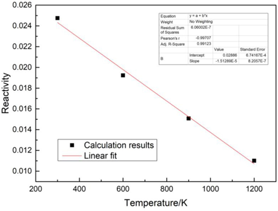
Figure 8. Reactivity varied with temperature.
Core Lifetime
A code MCORE coupling MCNP and ORIGEN is used to calculate the core life of the designed core. The thermal power is defined 2.4 MWt in the calculation. 613 depletion zones are considered and the time step is defined 0.25a. The effective multiplication factor change during the core life is shown in Figure 9. The lifetime of the heat pipe cooled reactor core is 14 years. Due to the depletion of burnable poison and fast neutron breeding effect, the effective multiplication factor increases at the beginning of life and then deceases when burnable poison run out until the end of life.
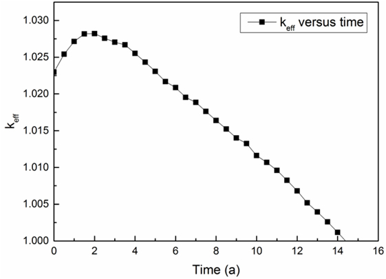
Figure 9. keff versus time.
Thermal Calculation
A one-dimensional FORTRAN code is used in thermal design and analysis of the micronuclear power source. As Figure 10 shows, a channel in active zone is defined as an area including a heat pipe and part of the surrounding fuels, air gaps, and matrix. One-dimensional calculation model for each channel is shown in Figure 10.
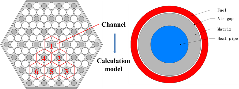
Figure 10. Channel in active zone and calculation model.
The temperature of the active zone channels is shown in Figure 11. Temperature distribution is consistent with the power density distribution obtained in Section “Power distribution.” Temperature in the air gap grows significantly from the matrix to the fuel surface. The maximum temperature of fuels is 2,203 K. The maximum power of heat pipes is 79.1 kWt.
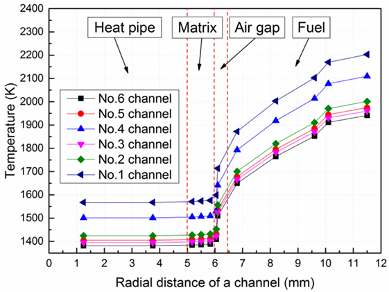
Figure 11. Temperature of active zone channels.
The temperature of thermocouple unit is also obtained by the same code. As shown in Figure 12, temperature of thermocouple unit varies from 924 to 1,240 K.
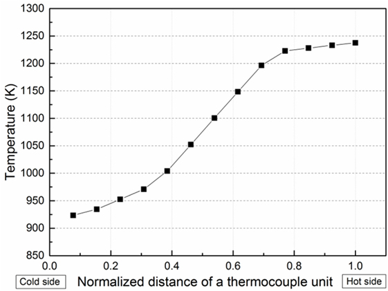
Figure 12. Temperature of thermocouple unit.
Conclusion
In this paper, a core of a heat pipe cooled reactor power source applied for underwater vehicle is designed. The core featured with 2.4 MWt thermal power, lifetime of more than 10 years, and low noise level basically fulfills the application demands. Six control drums with B4C neutron poison have the capability of controlling the reactivity and keeping the reactor safe. The main design parameters are as follows:
1) Uranium nitride fuel with 70% concentration of 235U and lithium heat pipe are adopted;
2) The maximum power peak factor is 1.42;
3) The reactivity temperature coefficient of the core is −1.513 pcm/K;
4) The core life is 14 years operating with designed thermal power;
5) The thermal design preliminarily satisfied the design standard.
This work provides a reference to the design and application of the micronuclear power source.
Author Contributions
HS: neutronic calculation; CW: system design; XL: thermal analysis; WT: system design revise; SQ: calculation results review; GS: paper writing guidance.
Conflict of Interest Statement
The authors declare that the research was conducted in the absence of any commercial or financial relationships that could be construed as a potential conflict of interest.
Acknowledgments
This work is carried out under the financial support of the China National Postdoctoral Program for Innovative Talents (Grant No. BX201600124), China Postdoctoral Science Foundation (Grant No. 2016M600796), and Key Supported Discipline of Guizhou Provence [QianXuewei He ZiZDXK(2016)24], 2011 Collaborative Innovation Center of Guizhou Province [Qian Jiao he xietongchuangxinzi (2016)02].
References
Bess, J. D. (2008). A Basic LEGO Reactor Design for the Provision of Lunar Surface Power. Technical Reports no. INL/CON-08-14353. Anaheim CA: Office of Scientific & Technical Information.
Bushman, A., Carpenter, D. M., Ellis, T. S., Gallagher, S. P., Hershcovitch, M. D., Hine, M. C., et al. (2004). The Martian Surface Reactor: An Advanced Nuclear Power Station for Manned Extraterrestrial Exploration. Massachusetts Institute of Technology. Center for Advanced Nuclear Energy Systems. Nuclear Space Applications. MIT-NSA-TR-003.
El-Genk, M. S. (2008). Space nuclear reactor power system concepts with static and dynamic energy conversion. Energy Convers. Manage. 49, 402–411. doi: 10.1016/j.enconman.2007.10.014
Kozlovskii, Y. M., and Stankus, S. V. (2014). Thermal expansion of beryllium oxide in the temperature interval 20–1550°C. High Temp. 52, 536–540. doi:10.1134/S0018151X1403016X
Li, X., and Wang, Z. (2003). Unmanned underwater vehicle technologies. Mar. Electr. Electr. Technol. 23, 12–14. doi:10.13632/j.meee.2003.06.005 (In Chinese).
Poston, D. I. (2000). The Heatpipe-Operated Mars Exploration Reactor (HOMER). Technical Reports no. LA-UR-00-5269. Los Alamos NM: Office of Scientific & Technical Information.
Poston, D. I., Kapernick, R. J., and Guffee, R. M. (2002). Design and Analysis of the SAFE-400 Space Fission Reactor[C]. American Institute of Physics, 578–588.
Rowe, D. M. (1991). Applications of nuclear-powered thermoelectric generators in space. Appl. Energy 40, 241–271. doi:10.1016/0306-2619(91)90020-X
Team, M. C. (2003). MCNP–A General Monte Carlo N-Particle Transport Code, Version 5. Book MCNP-A General Monte Carlo N-Particle Transport Code Version. 5. LA-UR-03-1987. New Mexico. LA: Los Alamos National Laboratory.
Urbatsch, T. J., Forster, R. A., Prael, R. E., and Beckman, R. J. (1995). Estimation and interpretation of keff confidence intervals in MCNP. Trans. Am. Nucl. Soc. 111, 169–182.
Yao, C., Hu, G., Xie, J., Zhao, S., and Guo, J. (2015). A scheme of lunar surface nuclear reactor power. Sci. Technol. Rev. 33, 19–23. doi:10.3981/j.issn.1000-7857.2015.12.002
Keywords: underwater, heat pipe cooled reactor, MCNP, ORIGEN, core design
Citation: Sun H, Wang C, Liu X, Tian W, Qiu S and Su G (2018) Reactor Core Design and Analysis for a Micronuclear Power Source. Front. Energy Res. 6:14. doi: 10.3389/fenrg.2018.00014
Received: 04 December 2017; Accepted: 28 February 2018;
Published: 22 March 2018
Edited by:
Jun Wang, University of Wisconsin-Madison, United StatesReviewed by:
Keyou Mao, Purdue University, United StatesClaudio Tenreiro, University of Talca, Chile
Copyright: © 2018 Sun, Wang, Liu, Tian, Qiu and Su. This is an open-access article distributed under the terms of the Creative Commons Attribution License (CC BY). The use, distribution or reproduction in other forums is permitted, provided the original author(s) and the copyright owner are credited and that the original publication in this journal is cited, in accordance with accepted academic practice. No use, distribution or reproduction is permitted which does not comply with these terms.
*Correspondence: Chenglong Wang, chlwang@mail.xjtu.edu.cn