Neutronics and Thermal Hydraulics Analysis of a Conceptual Ultra-High Temperature MHD Cermet Fuel Core for Nuclear Electric Propulsion
 Jian Song
 Weijian An2
 - 1Department of Nuclear Science Technology, Xi'an Jiaotong University, Xi'an, China
- 2Department of Reactor Engineering, China Institute of Atomic Energy, Beijing, China
Nuclear electric propulsion (NEP) offers unique advantages for the interplanetary exploration. The extremely high conversion efficiency of magnetohydrodynamics (MHD) conversion nuclear reactor makes it a highly potential space power source in the future, especially for NEP systems. Research on ultra-high temperature reactor suitable for MHD power conversion is performed in this paper. Cermet is chosen as the reactor fuel after a detailed comparison with the (U,Zr)C graphite-based fuel and mixed carbide fuel. A reactor design is carried out as well as the analysis of the reactor physics and thermal-hydraulics. The specific design involves fuel element, reactor core, and radiation shield. Two coolant channel configurations of fuel elements are considered and both of them can meet the demands. The 91 channel configuration is chosen due to its greater heat transfer performance. Besides, preliminary calculation of nuclear criticality safety during launch crash accident is also presented. The calculation results show that the current design can meet the safety requirements well.
Introduction
Interest in space exploration has developed rapidly in recent years and brought extensive research activity in the area of space propulsion that goes beyond present-day chemical systems (Valentian and Snecma, 2003; Wesley et al., 2011; James and Bruce, 2012). Among the available energy alternatives nuclear power offers important advantages and in many cases is the only viable alternative given actual operation conditions in interplanetary missions for that is the most compact form of energy available (Viorel, 2009). Nuclear propulsion systems, including nuclear electric propulsion (NEP) and nuclear thermal propulsion (NTP), are indispensable for manned deep space exploration. NTP can provide high specific impulse which is more than 2 times as the best chemical propulsion system, while NEP can give even much larger specific impulse than NTP (Thomas et al., 2005). Thus maximum payload capability and lowest launch cost can be achieved with NEP system. However, due to the low thrust capability of current electric propulsion system, large electric power is needed to maximize the thrust and minimize the trip time which is critical to the crew.
Power conversion efficiency is essential to NEP system. Among various power conversion systems, e.g., dynamic conversion cycles such as Stirling, Brayton, Rankine cycles, and static conversion systems such as thermoelectric, thermionic, Alkali-metal Thermoelectric Converter (AMTEC), and Magnetohydrodynamics (MHD), MHD possesses the highest efficiency (>40%), especially suitable for high-power space applications. Minimum thermal power, radiator area, and shielding mass can be realized with MHD power conversion system. The basic principle of MHD generation is to heat the working fluid to ionized plasma using reactor thermal power, then fast flow through a channel surrounded by perpendicular high magnetic field to produce electrical current under the effect of Lorentz force, demonstrated in Figure 1. The hot working fluid out from the power generation channel preheats the cold working fluid coming into the reactor in the heat exchanger and will be further cooled in the heat radiator, and finally passed through the compressor and turbine to the next cycle. Due to its high temperature, it is also possible to add a Brayton heat engine in the cold leg to enhance the efficiency of power generation. However, long-term operation in ultra-high temperature condition (>2,000 K) is a significant drawback to MHD system, and only NTP fuels may meet the requirements.
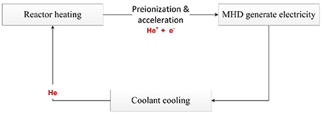
Figure 1. Operating principle of MHD reactor power system.
Recently, a concept of manned Mars exploration mission with NEP using closed MHD generator is proposed by China's Lunar and Deep Space Exploration Center (CLEP). The goal is to complete the space nuclear power supporting the interplanetary spacecraft, to achieve high efficiency MHD nuclear power conversion technology. Table 1 lists the main parameters of the overall spacecraft power system. This paper focuses on the reactor core design and optimization. A preliminary reactor concept using cermet fuel is carried out. The current modeling tool includes an iteration between reactor physics and thermal hydraulics calculations. In order to take the advantage of different software, MCNP5 and MVP are used for the nuclear reactor core modeling, neutronics, shielding, depletion analyses, and critical safety analysis. ANSYS-CFX is used for thermal hydraulic analysis and optimization.
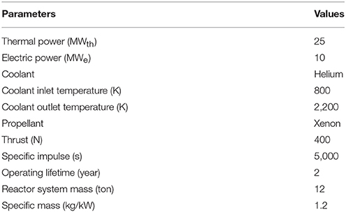
Table 1. Main parameters of the whole system.
Reactor Design
A reasonable design is provided that appear desirable from the standpoint of size, mass, safety, and reliability. The design work mainly consists of neutronics, thermal hydraulic and radiation shield.
Fuel Consideration
Apparently, the critical performances of the reactor lie in the ultra-high temperature and long term duration. Three kinds of ultra-high temperature fuel derived from mainstream NTP programs are considered, i.e., (U,Zr)C graphite-based fuel, mixed carbide fuel, and cermet fuel (Jahshan and Kammash, 2005; Jonathan et al., 2011).
Extensive research work was conducted of (U,Zr)C graphite-based fuel for thermal spectrum reactors during the Rover/NERVA program (1955–1972) that proved NTP to be a viable technology. However, there was still some issue, i.e., cracking of ZrC coating on the coolant channels, remained unresolved till the end of the program. It is a significant limiting factor to the reactor lifetime because it may lead to a catastrophic loss of graphite and fuel (Stewart and Bruce, 2012; Benensky, 2013). Since the lifetime of the reactor required by NEP is much longer than NTP, (U,Zr)C graphite-based fuel is considered not suitable for the present MHD reactor design.
Mixed carbide fuel forms, including di-carbides and tri-carbides, were developed by Soviet Union in heterogeneous reactor program for NTP (1950s-early 1990s) which shows several advantages. A “twisted-ribbon” geometry was chosen for fuel form to maximize heat transfer while preserving fuel shape and integrity under working conditions. However, the tri-carbide is very brittle and instability at high temperatures testing which makes the development of these fuel forms challenging (Benensky, 2013). Additionally, the manufacturing processes of this kind of fuel forms are very complicated and costly. So mixed carbide fuel is beyond the scope of consideration in the expectable future.
Cermet, another option of NTP fuels, were mainly pursued in parallel to basic graphite fuel development in GE-710 (by General Electric) and ANL (Argonne National Laboratory) fast spectrum propulsion reactor programs in 1960s. Current research on cermet fuel is being conducted as part of the Nuclear Cryogenic Propulsion Stage (NCPS) Advance Exploration System (AES) technology project at NASA's Marshall Space Flight Center (Gomez, 2014). A supercritical carbon dioxide cooled Mars surface power reactor with Brayton cycle designed by the Center for Space nuclear Research (CSNR) of Idaho National Laboratory also uses low-enriched uranium cermet fuel (Kevin et al., 2016). Cermet fuel forms are composed of a tungsten or molybdenum fuel element matrix material (Benensky, 2013). It is considered that cermet fuels may provide a significant design advantage over graphite fuel elements in the NERVA/Rover program, such as its potential for very long operating life and ability to restart (Stewart and Bruce, 2013). In particular, researches show that deformation but not cracking of the cermet fuel and cladding may occur under high stresses (Stewart and Bruce, 2013). Fast spectrum reactors also tend to be much more compact than thermal spectrum reactors and an inherent “neutronic spectral shift” safety feature that helps maintain reactor subcritical when submerged in water or in wet sand of the reentry accident. Therefore, cermet fuel element developed under the GE-710 program is chosen as a reference fuel form for the MHD conversion reactor design.
The appearance and design of fuel elements are influenced by several factors. Important geometry features includes the element size, the number of coolant channels, the channel diameter and the web thickness of the fuel matrix (Bruce and Stanley, 2012). In the application of W-UO2 cermet based fuel elements for MHD reactor power system, the cermet fuel matrix has a composition of W-60%UO2-6%Gd2O3 with W-25%Re as the cladding material both on the coolant walls and exterior. Specially, volumetric ratio 60% UO2 and volumetric ratio 6% Gd2O3 (as the oxygen stabilizer of UO2) are dispersed in the tungsten matrix. Each fuel element has a hexagonal cross section with a flat-to-flat distance of 2.316 cm. In the axis direction, the first 10.24 cm of fuel element inlet is filled with a beryllium oxide neutron reflector and the latter 60.96 cm is filled with the cermet fuel mixture. There is no neutron reflector at the outlet of fuel element because the core outlet temperature is too high. In order to get the optimal heat transfer performance, two kinds of coolant channel configuration designs were proposed. One configuration design based on the GE-710 reactor was modeled, where each fuel hex contained 61 coolant channels lined with 0.286 mm thick W-25%Re cladding layer and another was modeled to have 91 coolant channels each lined with a 0.204 mm same cladding layer. Design parameters of each fuel element are shown in Table 2. The surface-area to-volume-ratio of the 61 coolant channel hex is 0.57 compared to the 0.73 ratio with the 91 coolant channel hex. Figure 2 illustrates the hexagonal prismatic cermet fuel element that contains 91 coolant channels.
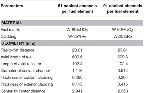
Table 2. Design parameters of the fuel element.
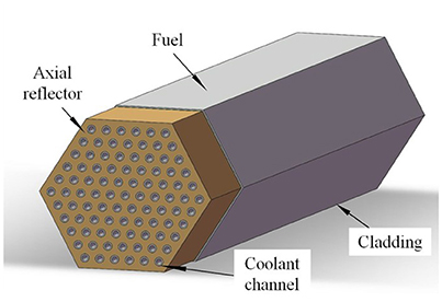
Figure 2. Fuel element configuration.
Reactor Description
The reactor core configuration is shown in Figure 3 and be designed as helium-cooled fast reactor. The radius of active zone is 21 cm. There're 246 fuel elements and 66 tungsten filler elements in the core. The 235U enrichment of central 30 fuel elements is 70%, while the outer ones possess 93% 235U enrichment. The purpose of this design is to flatten the power distribution and reduce the nuclear hot spot factor. The radial and axial reflectors are both made of BeO with the thickness of 10 cm. There are two ways to control the reactor reactivity. 16 absorbed drums in the radial reflector are mainly used to control the power level and can also be used to shut down the reactor independently. These control drums are divided into eight sets, with two control drums in each set sharing one drive mechanism and rotating at the same time. Each of drum has 120 degree surface absorber made of B4C and the thickness of absorber is 2 cm. A safety rod in the center of core with 4 cm diameter is used to increase the shutdown depth, which is particularly important for critical safety in launching accident. In normal operation, the safety rod is pulled out of the core. The overall height of the core is 71.2 cm and the total mass is 1616.9 kg. All the major core design results are summarized in Table 3.
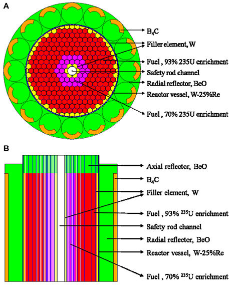
Figure 3. (A) Core configuration in cross-section. (B) Core configuration in axial-section.
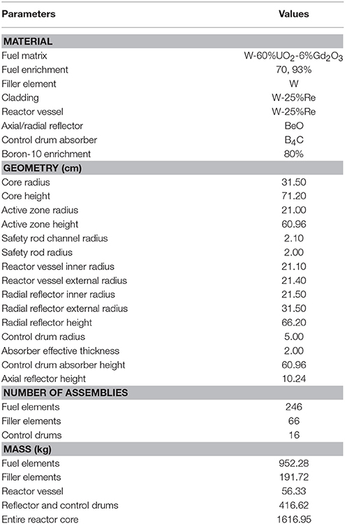
Table 3. Major design parameters of the reactor core.
Shielding Design
Shielding is an important part of the reactor system, mainly used for absorbing or weakening the large amount of neutrons and gamma rays released from the core. In this research, the main design goal of shielding design is to make sure the maximum irradiation dose of the astronauts is limited to 50 mSv per year at 51 m away from the reactor core. Figure 4 provided a 17° truncated cone-shaped preliminary shadow shielding design meets the demand, which can protect crew or equipment in specific areas. The total mass of radioactive shield is 9.98 t, with heavyweight shields on both sides and lightweight shield arranged in the middle of them. The lightweight shield is made of LiH, the best neutron shielding material known so far, which is very advantageous for reducing the weight of shielding. The heavyweight shield is made of W and is a commonly used material for shielding gamma rays in space reactors. The design of heavyweight shields on both sides can not only shield the gamma rays released by the core, but also shield the induced gamma rays and protect the lightweight shield. This shielding structure can be further optimized in the future to reduce mass.
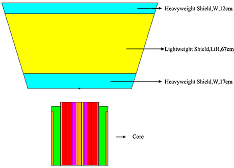
Figure 4. Shielding configuration.
Core Neutronics Analysis
Neutron physics calculation shows that the keff, ρ and βeff is 1.0417, 4.001 Δk/k% and 6.91 × 10⁻³ for cold state when the control drums are rotated outward at the beginning of core-life, respectively. While the keff, ρ and βeff is 1.0395, 3.78 Δk/k% and 6.05 × 10⁻³ for hot state, respectively. It can be seen from the data that the reactor has a negative temperature reactivity coefficient because the excess reactivity of hot state is lower than that of cold state, which is a key assurance for the inherent safety of nuclear reactor. When all the control drums are rotated inward (ρ = 6.136 Δk/k%) without the safety rod, the reactor can be shutdown with the keff equal to 0.9779. The reactivity worth of safety rod is 3.254 Δk/k%.
The total thermal power of the reactor core is 25 MWth. Normalized thermal power distribution of the reactor core is shown in Figure 5. It has a normalized peak-to-average thermal power ratio of 1.253. The corresponding maximum thermal power of the fuel elements (hot channel) is 0.1136 MWth. The average thermal power per fuel element (average channel) is 0.09158 MWth. Figure 6 shows the axial power distribution of the hot channel as well as the average channel. There is an obvious local power peak near the axial reflector due to reflected neutrons increasing fission reaction rate. In the calculation, it is assumed that the radial power distribution of each fuel element is uniform.
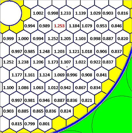
Figure 5. Normalized thermal power distribution of 1/4 core.
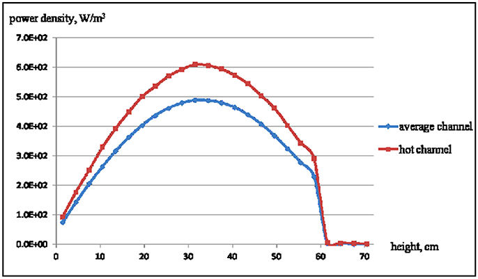
Figure 6. Axial power density distribution of hot channel and average channel.
Depletion calculation by MVP-BURN indicated that the operating lifetime of reactor is about 2 years which has 33% margin as the real operating time is about 1.5 years.
Apart from reactor physics design, preliminary critical safety analysis was also carried out using MCNP5. The reactor has to satisfy the stuck rod criterion: During the shutdown process, the reactor can be kept in subcritical with other control rods when the most valuable control rod is stuck outside of the core. As Figure 7 illustrates, when a set of control drums are stuck facing outwards of the reactor core and other control drums are turned to the core, the keff of the core is 0.9899. Therefore, the current reactor physics design can meet the requirement of stuck rod criterion.
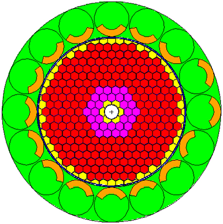
Figure 7. Calculation scenario when a set of control rod is stuck facing outboard of the core.
Launch failure reentry accident is unique to space reactor because the usual using of highly enriched fuel elements, which can easily lead to prompt supercritical accident. The thermal neutron absorption cross-section of cladding material tungsten-rhenium alloy (especially rhenium) is very large while the fast neutron absorption cross-section of that is very small, which is very helpful in operating efficiency and critical safety. Two severe conditions during launch are calculated, and the results show very inspiring safety performance. When the reactor is submerged in water and the inner voids (i.e., coolant channels and other clearance) are all flooded with water, the relevant keff is 0.9652. In another condition, the keff is 0.9664 when the reactor immersed in wet sand and the inner voids become full of water (as shown in Figure 8), which is the most serious critical accident scenario for space nuclear reactors. In the above calculation, all of the drums and safety rod were assumed at the largest position of reactivity worth.
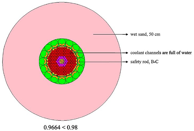
Figure 8. Calculation result of reentry accident in wet sand.
Core Thermal Hydraulics Analysis
The basic task of thermal hydraulics design is to ensure that the heat transfer capability of reactor core matches with the thermal power, and all the thermal parameters are maintained within the prescribed limits during operation with suitable safety margin. On the other hand, the core outlet temperature must be high enough (more than 2,200 K) in operating conditions to ensure the efficiency of MHD conversion. The core thermal power distribution is the main input parameter for thermal hydraulics analysis. In this section, the initial reactivity lifetime thermal power distribution calculated by MCNP5 was converted into the volumetric heat release rate and then put into ANSYS-CFX for thermal hydraulics calculation. Because the heat release peak power factor of fuel element in the end of reactivity lifetime is lower than that in the beginning, which will reduce the corresponding heat transfer requirements. Single channel steady state model was used for CFD calculations, contains average channel fuel element and hot channel fuel element.
The physical properties of core materials and coolant used in the thermal hydraulics analysis are listed in Table 4. These physical properties are constants at rated operating conditions and are suitable for steady state thermal hydraulics analysis. The density of gaseous helium depends on pressure and temperature. It also can be seen from Table 4 that the heat transfer performance of tungsten based cermet fuel is very good.
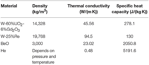
Table 4. Physical properties of reactor core materials and coolant.
The reactor is cooled by helium at a very high velocity, which belong to compressible flow since the flow velocity is very fast in the core. The helium enters the core channel at a temperature of 800 K and reference pressure is 1 MPa. The assumption in the calculation was that the flow rate of coolant in each channel is evenly distributed. The fluid domain was adopting the RANS technique which solve time averaged equations instead of solving the Navier-Stokes equations directly, which has been widely used in the engineering applications. The solid domain was solved by heat conduction equations with the no-slip boundary condition. The heat conduction and heat convection between fluid domain and solid domain were considered in this model. Thermal radiation inside the fuel element was neglected in the preliminary study. The shear stress transport (SST) κ-ω model was adopted to simulate the turbulent phenomenon. The most significant advantage of this model is that it can effectively integrate the advantages of different turbulent model: robust and accurate formation of the κ-ω model in the near wall region and free-stream independence of the κ-ε model in the far field.
The semi-structured mesh was generated using the ICEM software, show as Figure 9. A 1/6 sector (60° symmetry) was used to simplify the model and save calculation time due to the symmetry of fuel element geometry. Symmetrical boundary condition was adopted to the corresponding split surfaces of the sector and adiabatic boundary condition was adopted to the rest of solid outer surface. We used thermal equilibrium boundary conditions at the interface between different parts in the fuel element. An unstructured grid was adopted to the fuel matrix part, whereas a structured grid was applied to the coolant channels and cladding. In this way, it can be ensured that all the meshes quality are >0.7 when the aspect ratio of the fuel element is large. The models of two fuel element design cases contains approximately 1.89 and 2.76 million finite volume cells respectively, allowing the thermal power profile to be calculated with an axial mesh spacing of 1.78 mm. Mesh sensitivity analysis has been conducted.
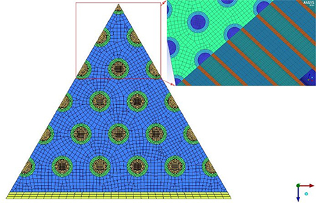
Figure 9. Cross sectional mesh of the 91 coolant channel fuel element and a zoomed-in view of center part.
The calculation results proved that there is neither obstruction nor supersonic flow in the process of coolant flow in the core. The calculation results of average channel determined that the core heat can be taken away safely and meet the design requirements when the coolant mass flow rate is 3.0996 kg/s. Figure 10 shows the axial temperature profile of the average channel for 91 coolant channel fuel element case. It can be seen that both coolant and fuel element temperature gradually increase in the axial direction, and the maximum value occurs at the coolant outlet. The temperature distribution between bocks in different axial regions is not smooth transition because of the segmented distribution of volumetric heat release rate given by neutron physics. There are two reasons that cause the fuel temperature achieve the highest at coolant channel outlet (Stewart and Bruce, 2008): Firstly, the large specific heat capacity and fast flow velocity of helium, and the large coolant channel length to diameter ratio (799:1) are conducive to heat transfer; secondly, the thermal conductivity of tungsten based dispersion fuel is excellent which can help to promote the temperature flattening in the axial direction.
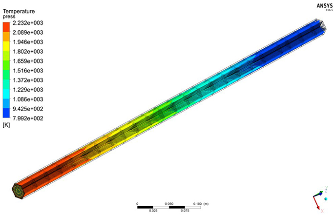
Figure 10. Axial temperature profile of the average channel for 91 coolant channel fuel element.
As demonstrated in Figure 11, the average coolant outlet temperature of 61 and 91 coolant channel element cases are about 2,250 and 2,217 K respectively while the peak fuel temperature are approximately 2,343 and 2,287 K respectively. The total core pressure drop are 1.067 MPa and 1.225 MPa respectively. For hot channel (as shown in Figure 12), the average helium outlet temperature for 61 and 91 coolant channel cases was about 2,595 and 2,558 K respectively while the peak fuel temperature is approximately 2,699 and 2,648 K respectively. The total core pressure drop is 1.162 and 1.328 MPa respectively. It can be seen that the average fuel temperature is always slightly higher than the coolant temperature, which also proves the good heat-conducting property of W-UO2 cermet fuel. Obviously, the fuel temperature of 61 channel case is 50–150 K higher than 91 channel case in the second half of hot channel. Larger volume ratio on the fuel element edge means more heat drains into edge channels, hence temperatures are higher. Due to the higher surface area to volume ratio, the peak temperature is lower for the 91 channel case than that for the 61 coolant channel case. It is foreseeable that this difference will be more distinct as the reactor power increases or the coolant flow rate drops.
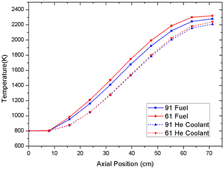
Figure 11. Axial temperature distribution of average channel.
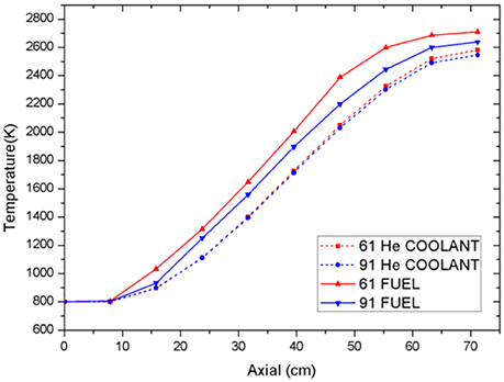
Figure 12. Axial temperature distribution of hot channel.
The radial temperature profile of 91 coolant channel case and 61 coolant channel case in Figures 13, 14 show the distribution of outlet temperature are substantially uniform distribution. The fuel zone near the edges has coolant channels on only one side, so the heat exchange capacity is relative low. The edge temperature is approximately 8 K higher than center temperature under the assumption of adiabatic boundary condition. Coolant velocity distribution is shown in Figure 15. The maximum rate is located in the center of coolant channel proved that the boundary layer of mesh can simulate flow characteristics very well.
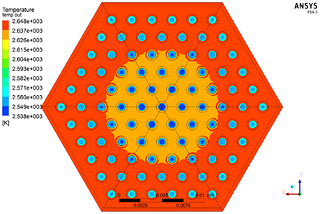
Figure 13. Radial temperature distribution of hot channel in 91 coolant channel case.
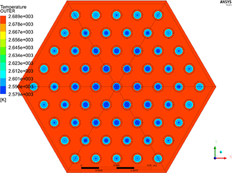
Figure 14. Radial temperature distribution of hot channel in 61 coolant channel case.
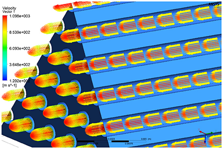
Figure 15. Coolant velocity distribution of average channel.
In conclusion, both of the configurations meet the requirements well. And the hot channel analysis indicates that the maximum temperature of the fuel is far below the limiting temperature (3,100 K) of cermet fuel (Robert et al., 2012). The heat transfer performance of 91 channel case is better than 61 channel case while pressure drop result is on the contrary. As for reactor design, we would prefer to the lower hot-spot temperature because of the mechanical properties requirement for long term operation in high temperature condition. So the 91 coolant channel configuration is chosen for preliminary design of the reactor finally. Table 5 shows the reactor core thermal-hydraulic design parameters.
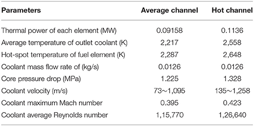
Table 5. Thermal-hydraulic parameters of the reactor core.
In normal operating condition, the minimum mass flow rate of coolant is 2.51 kg/s. The hot-spot temperature of fuel and pressure drop is approximately 3,110 K and 1.081 MPa, respectively. The results show that the reactor has sufficient thermal safety margin of 23.5%.
Conclusions
Manned Mars exploratory missions under CLEP research are progressively enabling the combination of space technology and nuclear technology for the theoretical breakthrough of high power space nuclear power and electric propulsion. A cermet-fueled reactor with MHD power conversion for NEP is designed and analyzed, which has the advantage of high energy conversion efficiency and high power density. Computation results show the current core design can meet the requirements very well. Furthermore, extensive research is necessary for preliminary ground demonstration verification, including full core CFD simulation, fluid-solid coupled analysis, transient analysis, and necessary experimental works.
However, cermet fuel technology, which is still being under development at NASA, is the key issue for the whole reactor concept and application. Many issues, especially degradation of mechanical integrity and loss of fuel, remain to be resolved (Haertling and Hanrahan, 2007). Meanwhile, manufacturing a reliable high-speed helium turbine is also a challenging technology (Isaac et al., 1993).
Author Contributions
JS: completed the thermal hydraulic design of the reactor system and wrote this article; WA: completed the reactor physics design of the reactor system; YW: funded the research and provided a computing platform for the reactor system design; WT: contributed to the cooperation between Xi'an Jiaotong University and the China Institute of Atomic Energy to jointly accomplish this research.
Conflict of Interest Statement
The authors declare that the research was conducted in the absence of any commercial or financial relationships that could be construed as a potential conflict of interest.
Acknowledgments
The authors express their thanks to staff at the Department of Reactor Engineering in CIAE who supported this work for many useful discussions. The research works of this subject is funded by the National 863 High Technology Research and Development Program (2012AA050908) and National Natural Science Foundation of China (Grant No. 11575141).
Abbreviations
B4C, boron carbide; BeO, beryllium oxide; βeff, effective delayed neutron fraction; Cermet, ceramic-metal fuel type; CFD, computational fluid dynamics; CLEP, China's lunar and deep space exploration center; keff, effective neutron multiplication factor; Gd2O3, gadolinium oxide; LiH, lithium hydride; MW, megawatts of energy; MHD, magnetohydrodynamics; NEP, nuclear electric propulsion; NTP, nuclear thermal propulsion; NASA, national aeronautics and space administration; ρ, excess reactivity; UO2, uranium oxide; W, tungsten; Re, rhenium.
References
Benensky, K. (2013). Summary of Historical Solid Core Nuclear Thermal Propulsion Fuels. Park, PA: Thoshiba Westinghouse Undergraduate Fellows Program, Pennsylvania State University.
Bruce, G., and Stanley, K. (2012). “Small fast spectrum reactor designs suitable for direct nuclear thermal propulsion,” in 48th AIAA/ASME/SAE/ASEE Joint Propulsion Conference & Exhibit (Atlanta, GA).
Gomez, C. (2014). Induction Heating Model of Cermet Fuel Element Environmental Test (CFEET). Daytona, FL: NETS-2014.
Haertling, C., and Hanrahan, R. J. Jr. (2007). Literature review of thermal and radiation performance parameters for high-temperature, uranium dioxide fueled cermet materials. J. Nucl. Mater. 366, 317–335. doi: 10.1016/j.jnucmat.2007.03.024
Isaac, M., Samim, A., Nils, J., and Edward, T. (1993). Ultrahigh temperature vapor-core reactor magnetohydrodynamic system for space nuclear electric power. J. Propuls. Power 9, 98–104. doi: 10.2514/3.11490
Jahshan, S., and Kammash, T. (2005). Multimegawatt nuclear reactor design for plasma propulsion systems. J. Propuls. Power 21, 385–391 doi: 10.2514/1.5456
James, E., and Bruce, S. (2012). “Cycle analysis of a 200MW class cermet based NTR engine,” in 48th AIAA/ASME/SAE/ASEE Joint Propulsion Conference & Exhibit (Atlanta, GA).
Jonathan, A., Brain, G., and William, T. (2011). “A combined neutronic-thermal hydraulic model of a CERMET NTR reactor,” in Proceedings of Nuclear and Emerging Technologies for Space (Albuquerque, NM).
Kevin, J., Akansha, K., Kurt, E., Yayu, M., and Steven, D. (2016). Neutronics and thermal hydraulics analysis of a low-enriched uranium cermet fuel core for a Mars surface power reactor. Ann. Nucl. Energy 96, 307–312. doi: 10.1016/j.anucene.2016.05.035
Robert, R., Jeramie, W., and Omar, R. (2012). “Fabrication and testing of CERMET fuel materials for nuclear thermal propulsion,” in 48th AIAA/ASME/SAE/ASEE Joint Propulsion Conference (Atlanta, GA).
Stewart, M., and Bruce, G. (2008). “Thermal hydraulic and structural analysis of nuclear thermal propulsion reactor core components,” in 44th AIAA/ASME/SAE/ASEE Joint Propulsion Conference & Exhibit (Hartford, CT).
Stewart, M., and Bruce, G. (2012). “Thermal, fluid, and structural analysis of a cermet fuel element,” in 48th AIAA/ASME/SAE/ASEE Joint Propulsion Conference (Atlanta, GA).
Stewart, M., and Bruce, G. (2013). “A comparison of materials issues for cermet and graphite-based NTP fuels,” in 49th AIAA/ASME/SAE/ASEE Joint Propulsion Conference & Exhibit (San Jose, CA). Available online at: https://ntrs.nasa.gov/search.jsp?R=20140010646#?
Thomas, M., Ryan, C., Steven, R., Douglas, I., and Neil, D. (2005). “The prometheus 1 spacecraft preliminary electric propulsion system design,” in 41th AIAA/ASME/SAE/ASEE Joint Propulsion Conference & Exhibit (Tucson, AZ).
Valentian, D., and Snecma, M. (2003). “A nuclear electric propulsion module for outer planets exploration,” in 39th AIAA/ASME/SAE/ASEE Joint Propulsion Conference (Huntsville, AL). Valentian D., Snecma M., Vernon
Keywords: space reactor, neutronics, thermal hydraulics, reactor design, cermet fuel, MHD generator, electric propulsion
Citation: Song J, An W, Wu Y and Tian W (2018) Neutronics and Thermal Hydraulics Analysis of a Conceptual Ultra-High Temperature MHD Cermet Fuel Core for Nuclear Electric Propulsion. Front. Energy Res. 6:29. doi: 10.3389/fenrg.2018.00029
Received: 14 February 2018; Accepted: 29 March 2018;
Published: 16 April 2018.
Edited by:
Jun Wang, University of Wisconsin-Madison, United StatesReviewed by:
Xin Li, Japan Atomic Energy Agency, JapanYago Rivera, Instituto Ingeniería Energética, Universidad Politécnica de Valencia (UPV), Spain
Copyright © 2018 Song, An, Wu and Tian. This is an open-access article distributed under the terms of the Creative Commons Attribution License (CC BY). The use, distribution or reproduction in other forums is permitted, provided the original author(s) and the copyright owner are credited and that the original publication in this journal is cited, in accordance with accepted academic practice. No use, distribution or reproduction is permitted which does not comply with these terms.
*Correspondence: Jian Song, sjian_eagle@163.com
Yingwei Wu, wyw810@mail.xjtu.edu.cn