Arctic Anthropogenic Sound Contributions from Seismic Surveys during Summer 2013
 Mike van der Schaar
 Anja J. Haugerud2
  Jürgen Weissenberger
- 1Laboratori d'Aplicacions Bioacústiques, Universitat Politècnica de Catalunya, Barcelona, Spain
- 2Statoil ASA, Trondheim, Norway
Statoil deployed three acoustic recorders from fall 2013 to 2014 in the Arctic region as part of a broad scientific campaign. One recorder was installed in the Barentsz Sea south-east of Spitsbergen. Two other recorders were installed in the Greenland Sea north-east of Greenland. All recorders were operating at a duty cycle of 2 min on and 30 min off, sampling at 39,062 Hz and recording in 24 bits. The Greenland recorders both captured air gun surveys performed during the summer months of 2013, allowing to estimate the transmission loss in the Arctic over long ranges. This paper presents “log(R)” transmission loss curves for these scenarios that can help assessing the acoustic shipping impact for future expeditions.
1. Introduction
With the opening of shipping routes and improved economic availability of the arctic the anthropogenic activities have been increasing over the last few years in that area (Stephenson et al., 2011). At the same time, sound pollution has become an important issue where there is concern not only about how sound may affect marine mammals (Southall et al., 2007) but also concerning its affect on fish (Casper et al., 2013), cephalopods (André et al., 2011), and other organisms (Solé et al., 2016). These affects can lead in extreme cases to direct harm of an animal or more often to masking of acoustic signals reducing communication of forraging ranges (Jensen et al., 2009). In the European Union, this concern about sound pollution has resulted in a special section in the Marine Strategy Framework Directive where sound levels have to be monitored and high intensity sounds have to be cataloged (European Parliament and the Council of the European Union, 2008). It is likely that similar requirements will become the norm for operations outside of EU coastal waters such as the arctic zone which has a rich marine mammal diversity. Actual measurement of sound contributions from activities is not always possible or practical due to costs or the difficult artic environment. In many cases source sound levels related to these activities may be available, but the sound propagation ranges, and the sphere of influence, is often decided using modeling techniques (Sigray et al., 2016).
This report presents opportunistic data of sound measurements made by two recordings deployed by Statoil during the 2013–2014 season that recorded seismic surveys using air guns performed in the area at distances up to 300 km away. The surveys were performed during the months August, September, and October of 2013 (a duration of about 50 days). Availability of the survey ship position then permitted to compare received sound levels with source distance and to estimate the parameters of the most basic sound propagation loss model: C log10(R). Where C is often set to 20 for spherical loss, to 10 for cylindrical loss, or somewhere in between to account for sound channels with partically reflecting surfaces. In this report, C is estimated for long range propagation loss using the received levels from the air gun used in the seismic survey. These results may be compared with for example the shallow water loss curves for the Barentsz Sea provided in Jensen et al. (2000) that show very high low frequency losses (over 100 dB at 50 Hz at 10 km range) or empirical data in deep water in DiNapoli and Mellen (1986) (around 82 dB at 50 Hz at 100 km range). Additionally this may serve as input or control for low frequency arctic modeling (Gavrilov and Mikhalevsky, 2006; Alexander et al., 2013).
2. Materials and Methods
2.1. Recording Equipment
The Greenland I recorder was deployed during the Oden Arctic Technology Research Cruise 2013 on August 23 at 78° 30′N and 10° 0′E (Figure 1A) and recovered the next year on September 17. The location was about a 120 km away from the continental slope (a zone where sperm whale activity could be expected). The Greenland II recorder was deployed during the Oden Arctic Technology Research Cruise 2013 on August 22 at 76′ 30′N and 14° 20′E and recovered the next year on September 17. The depth at both deployment locations was around 200 m. The recorders were attached to a line suspended a few tens of meters above the sea floor using a subsurface float. The lines were recovered with the use of an acoustic release.
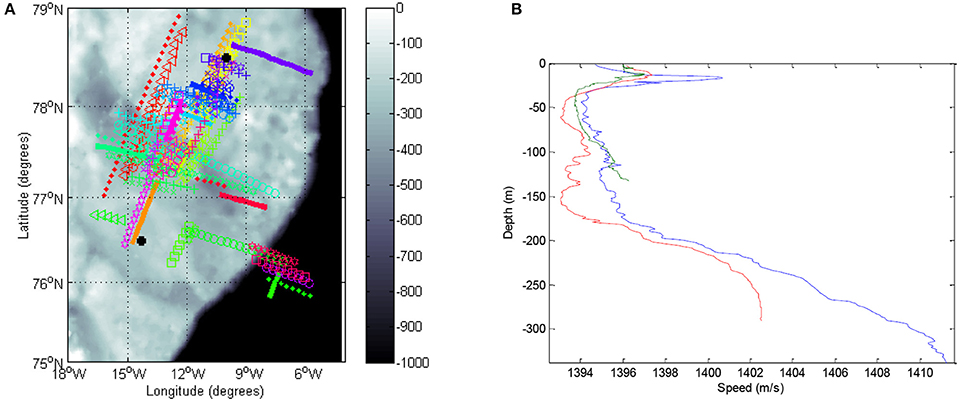
Figure 1. Overview of the deployment area: (A) survey vessel and recorder positions together with bathymetric information (the color bar shows the depth in meters); (B) Sound speed profiles at the two recorders (red: Greenland I, green: Greenland II) and a location in between the two recorders (blue).
In both recorders, the data was recorded with a duty cycle of 2 min on and 30 min off sampling at 39,062 Hz in 24 bits. The sampling frequency was chosen to allow a longer deployment time than 1 year in case its recovery would be delayed due to weather conditions. The hydrophone (AGUAtech Low-Power Scientific Measurement Hydrophone) sensitivity was –160 dB re 1 V/μPa; the data was quantized between ±2.5 V. The hydrophones were connected to channel B on the two recorders which had gain correction parameters of –0.732 dB (Greenland I) and –0.576 dB (Greenland II), respectively.
2.2. Sound Speed Profiles
Sound speed profile data was obtained from the NOAA-NODC World Ocean Database 2013 to have some idea of the propagation properties of the environment. Pressure and salinity information was entered into the UNESCO equation to compute a sound speed profile. Three profiles are shown in Figure 1B. The red line was obtained from cruise #4832 (cast #12258746) recorded at 78.832 latitude and –9.998 longitude on September 10, 2003. In this case, pressure was not recorded and it was estimated from the depth. The green line was obtained from cruise #9719 (cast #3288290) recorded at 76.958 latitude and –14.203 longitude on September 9, 1984. The blue line was obtained from cruise #10547 (cast #9922885) recorded at 77.573 latitude and –12.3 longitude on September 3, 2000.
All three profiles were made around the same time of year as the seismic survey was performed. The recorders were installed below a possible acoustic channel at a depth of around 100 m. In any case, the airguns were towed well-above the sound channel, limiting the amount of acoustic energy that would have been trapped by it.
Based on the recordings, the frequency band considered to be most interesting was the third octave band centered on 40 Hz. Higher frequencies were not always as clearly apparent at long distances and below 20 Hz the airgun energy started to reduce. Absorption of this frequency in sea water is below 0.01 dB/km (Mellen et al., 1987; Ainslie and McColm, 1998) and was ignored in this analysis in light of the presence of greater sources of error and propagation distances under 300 km.
2.3. Airgun Shot Detection
Airgun shots were detected automatically using a basic magnitude threshold detector requiring peaks to be at least twice over the background noise level. The background noise level was estimated before each detected shot by taking a 0.5 s sample 5 s before the detected peak. The configured duty cycle only provided 2 min of continuous data at a time. For detected shots to be included in the analysis at least 5 shots had to be detected in the recording and not more than 13; the latter would indicate a recording with a large amount of impulsive noise from other sources. Additionally, detections were eliminated if they did not follow a pattern of about 11 s intervals. Shots with received peak levels over 160 dB re 1 μPa2 were excluded as they were likely affected by saturation. A shot was defined as starting 0.1 s before the detected peak and ending 0.1 s after it. Considering the large number of available shots that were detectable well-above the background noise, no efforts were made to fine-tune the detector to detect weaker impulses. However, as explained further below, the shots were not always equally well-defined due to bottom and surface interactions. In total, 10,076 shots detected at Greenland I and 11,391 shots detected at Greenland II were used.
2.4. Seismic Survey Data
Positional data was made available through a datasheet provided by Statoil containing the position and time of the air gun shots. All gun shot recordings were made in the months August–October 2013. The survey tracks are shown with a different color/shape combination for each run in Figure 1A. The positional data was not entirely consistent with occasional mixing of shots made under the same operating name and time, but at a very different position. These positions were much less frequent than the regular gun shots and were filtered away using a median distance estimate taken over ship positions from a time interval around the recorder timestamp.
A broadband source level estimate of the array is published in the GUNDALF array modeling suite report (Goppen, 2011) and gives as 252 dB re 1 μPa at 1 m for the zero to peak level (RMS pressure 229 dB re 1 μPa at 1 m). These values are understood to be used for long range modeling and are not correct very close to the array. The source level in a frequency band around 40 Hz was not known.
The distance between the survey vessel and each recorder is shown in Figure 2. The color and shape of the different runs follows the same scheme as in Figure 1A.
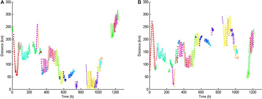
Figure 2. Distance between the survey vessel and recorders during August–October 2013: (A) recorder I; (B) recorder II.
2.5. Time Synchronization
It was assumed that the ship timestamps were synchronized through GPS; the recorder times were configured before deployment, but they may have some unknown drift. To synchronize the clocks it was initially planned to find the start of an airgun run after a long pause that was recorded. There are more than enough pauses in the airgun deployment, but the duty cycle of the recorders made it more difficult to find such an event. Unless the clocks are very much out of synchronization, it seems that shooting started before the shots were registered in the shot datasheet, and also continued for some time after. This made it impossible to find a reliable moment for synchronization. In order to find the ship range for each detected shot on the recorder all ship ranges in a 5 min time interval before and after the shot (10 min in total) were collected and the final range was evaluated through a median. The error with respect to the distance of the ship is considered to be small, minimizing at the same time the effect of spurious airgun activations discussed above.
2.6. Shot Measurement
For the comparison of measurements, it is important to understand what the automated algorithm is measuring. Figure 3 shows airgun signals passed through a third octave band filter centered on 40 Hz from three different survey vessel locations and registered at the Greenland II recorder. Each image shows the superposition of all the signals detected inside a single run file of 2 min. The top two images were recorded with the vessel at roughly 20 km distance. The bottom image with the vessel at 50 km distance.
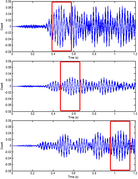
Figure 3. Three air gun shot sequences from the Greenland II recorder. All images show the pulses detected in a single run file (2 min) synchronized using cross correlation with the first pulse in the recording. The top two ones were fired from a distance of 20 km, the bottom one from 50 km.
There is an obvious difference in recorded levels between the two 20 km recordings, but first the detection algorithm is evaluated. The detector looks for the peak level and then takes a window of 0.1 s on both sides to compute the SPL. The airgun signals in the images actually consist of multiple pulses (about three or more) of different intensity; the strongest pulse is not always at the same position. This means that the algorithm may not always take the SPL measurement over the same part of the recorded signal, as shown with the rectangles in the images. The total window length of 0.2 s was selected to cover a complete single pulse and the level of the strongest pulse present in the signal is what is used to evaluate transmission loss, in addition to changes in the peak level itself. Considering the sampling rate of the recording (many times higher than necessary for the band being measured) the peak level itself should be fairly accurately estimated.
There is a fairly large difference in received levels at 20 km distance in Figure 3. The bathymetry profiles between the ship position and Greenland II recorder was inspected and were found to be similar: a gradual increase in elevation of 40–50 m. Ship shielding at seismic frequencies is not expected to play any role here. There was a difference in the array orientation but the airgun array is assumed to have omnidirectional radiation patterns. The low received levels in Figure 3 were recorded just when a pause was made. It is not known if reduced levels were used as an Acoustic Deterrent Device which would have some effect on the transmission loss estimation; however, if enough shots were made at constant level these outliers can be ignored by the modeling process.
3. Results
3.1. Greenland I
First the received sound pressure level in the third octave band centered on 40 Hz (SPL) and the received peak level (PL) in the same band are considered at the Greenland I recorder. Figure 4 shows the SPL and PL against the survey vessel distance up to a distance of 300 km. The red line is a logarithmic fit on the measurements; the green line represents spherical transmission loss. The root-mean-square of the residuals of each fit is reported as the “residual RMS.” The transmission loss follows a pattern much larger than spherical. In arctic waters it is not unusual to find high losses at some distance from the source due to dissipation of reflective rays.
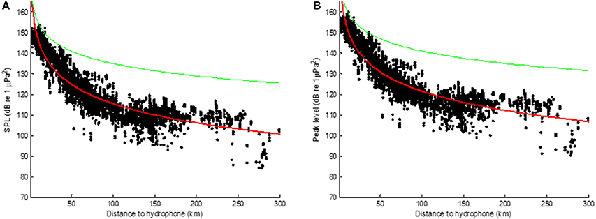
Figure 4. Received level in the third octave band centered on 40 Hz (A) and received peak level (B) at the Greenland I recorder. The green line represents spherical loss; the red line is a logarithmic fit with optimal parameters –31 log10(R) (with residual RMS = 5.0 dB) for both graphs.
The logarithmic fit in Figure 4 does not follow the curve of the data very well and a single “log(R)” rule does not seem sufficient. To look at the loss close to the source a smaller selection of data was taken based on the distance graphic in Figure 2. At the end of September and beginning of October (860–990 h) the survey vessel came closest to Greenland I. Matching the track colors and shapes in Figure 1A these tracks appear to go almost straight over the recorder, providing very similar conditions for the measurements. The received levels of that time period are displayed in Figure 5 (black dots) together with background noise levels (blue dots) showing that all the shots are well-above background noise levels. The transmission loss was now close to spherical, but still quite high. From around 40 km distance the “near distance” model starts to fail and another fit is required. Figure 5B shows the transmission loss for distances from 50 km together with background noise level estimates. The logarithmic fit follows the data fairly well. The received levels have a spread of around 10 dB at each distance. Using a combination of the two models a prediction could be made below 5 dB error (based on the residual RMS-values).
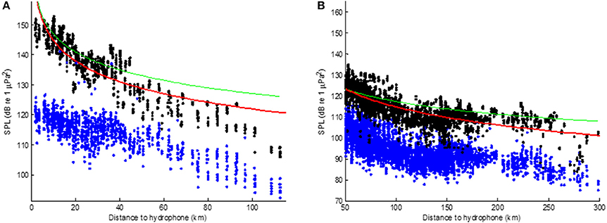
Figure 5. Logarithmic fit on the sound levels of the third octave band centered on 40 Hz for measurements up to 150 km away using data from hours 860 to 990 (A) and measurements between 50 and 300 km away (B) from the Greenland I recorder. Level measurements are in black; background noise measurements are in blue. The green line represents spherical loss; the red line is a logarithmic fit. The optimal fit up to 50 km range (A) has parameters –16 log10(R) (residual RMS = 4.2 dB) and beyond 50 km (B) –29 log10(R) (residual RMS = 4.6 dB).
The background noise levels plotted in Figure 5 seem to be coupled to the distance to the survey vessel in a very similar way as the shots. The operational noise from the survey propagates well at least up to 300 km.
3.2. Greenland II
The data from the Greenland II recorder will be presented in a similar fashion as those from Greenland I. The peak level measurements followed the 40 Hz levels closely and are not provided. In Figure 6, the 40 Hz SPL measurements are shown with a logarithmic fit (red) and spherical transmission loss (green). The transmission loss behaves much more spherical than at Greenland I, with slightly less than spherical loss at large distances.
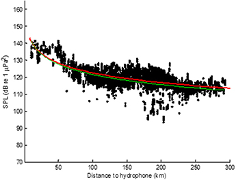
Figure 6. Received level in the third octave band centered on 40 Hz at the Greenland II recorder. The green line represents spherical loss; the red line is a logarithmic fit with optimal parameters −19 log10(R) with residual RMS = 4.2 dB.
At close range the model does not fit the data very well. On September 3 and 4 the survey vessel made two very similar tracks nearby the recorder. These correspond to the orange and purple tracks close to the Recorder II in Figures 1A, 2 (260–285 h). The variation in received levels was large, which was discussed above in relationship with Figure 3. Fitting a logarithmic model only on the levels received at a distance of 50 km or more, as was done in Figure 5 for Greenland I, resulted in parameters –18 log10(R) with residual RMS = 4.2 dB. As with the Greenland I recorder, the background noise levels follow a similar pattern as the airgun shots related to the survey vessel distance (not shown in plot), indicating that the survey itself is the dominant contributor during that time.
Interestingly, in e.g., Figure 6, which shows the received peak levels as in Figure 4B, there is a clear drop in both airgun shot levels and background noise levels of around 20 dB. This could be due to the bathymetry. From that position, there was an underwater ridge at about 136 km from the ship, 50 km from Recorder II with its peak around 25 m above the recorder depth, possibly blocking a fair amount of sound. A similar effect was not as apparent in the data from Recorder I as most of the survey tracks were made on the north side of it.
4. Conclusion
From the data presented above, it appears difficult to define a “log(R)” when the source is close to the recorder. Figures 5, 6 give very different estimates of the transmission loss with the former showing a loss much larger than spherical and the latter a loss somewhat smaller. However, there was less data available at close distances which made it more difficult to average out level fluctuations due to operational or environmental circumstances.
A large amount of data was available for both recorders for larger distances, but at any particular distance the spread of the received levels was in the order of 10 dB. To clean up the data the levels were binned at 4 km intervals from 50 up to 250 km. The results are shown in Figure 7, where the transmission loss at both recorders is reasonably modeled by spherical transmission loss. There are bumps in the curves where the propagation path may have been optimal or partially blocked, but as an order of magnitude estimation a model using –22 log10(R) seems to be a good approximation for this area during summer months.
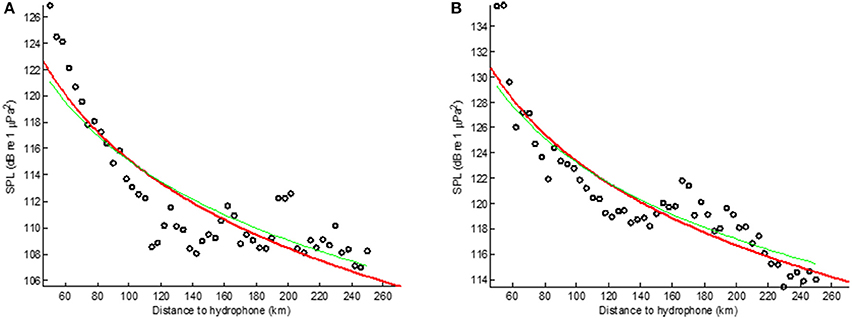
Figure 7. Logarithmic fit on the sound levels of the third octave band centered on 40 Hz for measurements from 50 km away and binned at 4 km intervals; (A) Greenland I and (B) Greenland II. The green line represents spherical loss, the red line an optimal logarithmic fit, in both cases −22 log10(R); the residual RMS was 2.3 dB (A) and 2.0 dB (B). These curves are based on summer data from August to October 2013.
Author Contributions
Mv, MA, and SD contributed to the data analysis of all recordings. AH, JW, and MA contributed to the deployment and acquisition of the data. All authors contributed to the draft and revisions of this article.
Conflict of Interest Statement
The authors declare that the research was conducted in the absence of any commercial or financial relationships that could be construed as a potential conflict of interest.
Acknowledgments
The authors thank Ingebret Gausland from Statoil for fruitful discussions on the article content.
References
Ainslie, M., and McColm, J. (1998). A simplified formula for viscous and chemical absorption in sea water. J. Acoust. Soc. Am. 103, 1671–1672.
Alexander, P., Duncan, A., Bose, N., and Smith, D. (2013). Modelling acoustic transmission loss due to sea ice cover. Acoust. Aust. 41, 79–87.
André, M., Solé, M., Lenoir, M., Durfort, M., Quero, C., Mas, A., et al. (2011). Low-frequency sounds induce acoustic trauma in cephalopods. Front. Ecol. Environ. 9, 489–493. doi: 10.1890/100124
Casper, B., Smith, M., Halvorsen, M., Sun, H., Carlson, T., and Popper, A. (2013). Effects of exposure to pile driving sounds on fish inner ear tissues. Comp. Biochem. Physiol. A 166, 352–360. doi: 10.1016/j.cbpa.2013.07.008
DiNapoli, F., and Mellen, R. (1986). Low Frequency Attenuation in the Arctic Ocean. Boston, MA: Springer US, 387–395.
European Parliament and the Council of the European Union (2008). Directive 2008/56/ec of the european parliament and of the council of 17 june 2008 establishing a framework for community action in the field of marine environmental policy (marine strategy framework directive). Offic. J. Eur. Union L164, 19–40.
Gavrilov, A., and Mikhalevsky, P. (2006). Low-frequency acoustic propagation loss in the arctic ocean: Results of the arctic climate observations using underwater sound experiment. J. Acoust. Soc. Am. 119, 3694–3706. doi: 10.1121/1.2195255
Goppen (2011). Gundalf Array Modelling Suite - Array Report. Technical Report Gundalf revision AIR7.1b, Date 2011-08-19, Epoch 2011-07-15, SMNG.
Jensen, F., Bejder, L., Wahlberg, M., Aguilar Soto, N., Johnson, M., and Madsen, P. (2009). Vessel noise effects on delphinid communication. Mar. Ecol. Prog. Ser. 395, 161–175. doi: 10.3354/meps08204
Jensen, F., Kuperman, W. A., Porter, M. B., and Schmidt, H. (2000). Computational Ocean Acoustics. New York, NY: Springer-Verlag.
Mellen, R., Scheifele, P., and Browning, D. (1987). Global Model for Sound Absorption in Sea Water Part III: Arctic Regions. Technical Report 7969, Naval Underwater Systems Center.
Sigray, P., Andersson, M., Pajala, J., Laanearu, J., Klauson, A., Tegowski, J., et al. (2016). BIAS: A Regional Management of Underwater Sound in the Baltic Sea. New York, NY: Springer New York, 1015–1023.
Solé, M., Lenoir, M., Fontuño, J., Durfort, M., van der Schaar, M., and André, M. (2016). Evidence of cnidarians sensitivity to sound after exposure to low frequency noise underwater sources. Sci. Rep. 6:37979. doi: 10.1038/srep37979
Southall, B., Bowles, A., Ellison, W., Finneran, J. J., Gentry, R., Greene, C. Jr., et al. (2007). Marine mammal noise exposure criteria: initial scientific recommendations (2007). Aquat. Mammals 33, 1–121. doi: 10.1578/AM.33.4.2007.411
Keywords: acoustics, arctic, airgun, noise measurement, propagation loss
Citation: van der Schaar M, Haugerud AJ, Weissenberger J, De Vreese S and André M (2017) Arctic Anthropogenic Sound Contributions from Seismic Surveys during Summer 2013. Front. Mar. Sci. 4:175. doi: 10.3389/fmars.2017.00175
Received: 31 January 2017; Accepted: 19 May 2017;
Published: 13 June 2017.
Edited by:
Tomaso Gaggero, Universit di Genova, ItalyReviewed by:
Sara Pensieri, Institute of Intelligent Systems for Automation (CNR), ItalyPaola Picco, Istituo Idrografico della Marina, Italy
Copyright © 2017 van der Schaar, Haugerud, Weissenberger, De Vreese and André. This is an open-access article distributed under the terms of the Creative Commons Attribution License (CC BY). The use, distribution or reproduction in other forums is permitted, provided the original author(s) or licensor are credited and that the original publication in this journal is cited, in accordance with accepted academic practice. No use, distribution or reproduction is permitted which does not comply with these terms.
*Correspondence: Michel André, michel.andre@upc.edu