Corrosion Fatigue Studies on a Bulk Glassy Zr-Based Alloy under Three-Point Bending
 Daniel Grell
 Yannic Wilkin1
- 1Materials Testing, University of Kaiserslautern, Kaiserslautern, Germany
- 2Leibniz-Institute for Solid State and Materials Research IFW Dresden, Dresden, Germany
Corrosion fatigue (CF) tests were carried out on bulk glassy Zr52.5Cu17.9Al10Ni14.6Ti5 (Vitreloy 105) samples under load-controlled three-point bending conditions with a load ratio of R = 0.1 in 0.01 M Na2SO4 + 0.01 M NaCl electrolyte. During cyclic testing, the bar-shaped specimens were polarized in situ at constant potentials and the current was monitored. Three different anodic potentials within the interval between the pitting potential EP and the repassivation potential ER and three different load amplitudes were applied. In some cases, in situ microscopic observations revealed the formation of black corrosion products in the vicinity of the crack tip during anodic polarization. Fractographic analysis revealed a clear distinction between two modes of crack growth characterized by smooth dissolution induced regions on the one hand and slim fast fracture areas on the other hand. Both alternating features contributed to a broad-striated CF fracture surface. Moreover, further fatigue tests were carried out under free corrosion conditions yielding additional information on crack initiation and crack propagation period by means of the open circuit potential (OCP) changes. Thereby, a slight increase in OCP was detected after rupture of the passive layer due to bare metal exposed to the electrolyte. The electrochemical response increased continuously according to stable crack propagation until fracture occurred. Finally, the fracture surfaces of the CF samples were investigated by energy dispersive X-ray with the objective of analyzing the elemental distribution after anodic dissolution. Interestingly, anodic polarization at a near repassivation potential of −50 mV vs. saturated calomel electrode (SCE), which commands a constant electric potential of E = 0.241 V vs. standard hydrogen electrode (SHE), led to favorable effects on the fatigue lifetime. In conclusion, all results are conflated to a CF model for bulk glassy Vitreloy 105 under anodic polarization in chloride-containing electrolyte and compared to the previously proposed stress corrosion mechanisms under similar conditions.
Introduction
In the last decades, bulk metallic glasses (BMGs) have gained increasing attention due to their outstanding mechanical properties, e.g., high fracture strengths, which are comparable not only to those of high-strength steels but also high elastic limits and good corrosion resistance (Trexler and Thadhani, 2010; Suryanarayana and Inoue, 2011). Especially Zr-based bulk glassy alloys combine additionally very good glass-forming ability with high hardness and good wear resistance at the same time making them favorable for various industrial applications like sporting goods, tools, springs, and micro electromechanical systems (Ashby and Greer, 2006; Inoue and Takeuchi, 2011). However, their breakthrough as structural materials has been missing so far due to their expensive manufacturing costs, lack of plastic strains under mechanical loading, and usually poor fatigue properties (Hess et al., 2006). Also important for industrial applicability of Zr-based BMGs is the knowledge of their corrosion resistance in various aqueous environments because mechanical damage can be superimposed by electrochemical processes resulting in environmentally induced cracking phenomena.
The poor fatigue behavior of most BMGs in air depends highly on prevailing loading conditions (Hess et al., 2006). Four-point bending tests conducted at a load ratio of R = 0.1 revealed an endurance limit that was defined as ratio between highest endured stress amplitude σa and ultimate tensile stress σUTS, of only 0.05 for Vitreloy 1 (Menzel and Dauskardt, 2006). In contrast, uniaxial compression–compression cyclic loading resulted in a significantly increased resistance against crack initiation and propagation (Hess et al., 2006). While Vitreloy 105 shows probably the highest strength-normalized fatigue endurance of ~0.24 (Naleway et al., 2013), which is also comparable to some high-strength steels, many attempts have been taken to improve the fatigue performance of BMGs. For example, Launey et al. (2009) developed glass matrix composites with microstructural length scales of the second phase according with mechanical crack length scales (Launey et al., 2009). A retarded growth of small flaws acting as preferential crack initiation sites was achieved, and subsequent failure by single shear band opening could be impeded. Enlarging fatigue life is also considered to be realized by surface modifications with a positive effect on shear band formation. Unfortunately, in a previous study on shot-peened Zr-based BMG samples, the fatigue life could not be influenced decisively, but crack initiation was shifted to the compressed subsurface region with multiple shear banding (Kruzic, 2011). Usually, shear bands initiate at small surface flaws serving as stress concentrators at an angle of ~50° to the maximum normal stress axis according to the Mohr–Coulomb criterion (Lund and Schuh, 2004; Vargonen et al., 2012). Crack initiation takes place at these shear bands, cracks propagate along them in mixed mode until a critical length is reached, and they continue growing rapidly perpendicular to normal stresses under mode I until failure. Fractographic analysis revealed three distinct regions of the fracture surface: the crack initiation site, a region of stable crack growth which is marked by fine striations, and a fast fracture region with a vein-like morphology due to unstable crack propagation (Hess et al., 2006). The fatigue striations were found to result from alternating crack tip blunting and re-sharpening. These mechanisms are influenced by numerous shear-banding events in a plastic zone right in front of the crack tip providing various shear planes for striated crack growth. Influencing these shear banding mechanisms in front of the crack tip is supposed to be beneficial to fatigue life properties of BMGs.
The effect of hydrogen on mechanical properties of Zr-based BMGs has been widely reported, and the related mechanisms are already well understood (Suh and Dauskardt, 2000, 2001; Ismail et al., 2001; Gebert et al., 2002; Mattern and Gebert, 2003; Hasegawa et al., 2004; Wang et al., 2004; Shan et al., 2005; Scully et al., 2007; Yoo et al., 2010; Li et al., 2013). Furthermore, there are several investigations on their stress corrosion cracking (SCC) behavior (Ritchie et al., 2000; Scully and Lucente, 2005; Scully et al., 2007; Nakai and Yoshioka, 2010; Kruzic, 2011; Gostin et al., 2015a). That is also highly relevant for many technical applications, but loading conditions at slow strain rates and static testing cannot represent real circumstances at all. Numerous studies on the corrosion fatigue (CF) behavior of fully amorphous Zr-based alloys have attempted to fill this gap. Thereby, various experimental methods, e.g., loading conditions, electrolytes, and electrochemical set-ups, were applied and different alloy compositions were investigated aggravating a systematic comparison of the results. Ritchie et al. (2000) observed three orders of magnitude higher fatigue crack growth rates of their glassy Zr41.2Ti13.8Cu12.5Ni10Be22.5 (Vitreloy 1) samples in 0.5 M NaCl solution under free corrosion conditions compared to those in air. This was attributed to a reduced protective effect of the naturally forming oxide-based passive layer against crack initiation and propagation due to the action of aggressive chloride ions. Furthermore, the application of anodic potentials was found to cause an increase of crack growth rates by several orders of magnitude. Fundamental investigations on CF of the same glassy alloy were provided by Schroeder et al. (1999) and Schroeder and Ritchie (2006). They determined the threshold value for fatigue crack initiation ΔKth to be 0.9 MPa√m in aqueous solution instead of 3 MPa√m tested in air. In addition, crack growth rates in the stable region revealed a proportional dependence from the chloride concentration varying between 0.5, 0.05, and 0.005 M under open circuit testing conditions. Nakai and Yoshioka (2010) observed a very similar fatigue behavior for their Zr55Cu30Ni5Al10 samples in comparable experiments. The corrosion resistance and CF performance of various Zr-based BMGs was investigated under free corrosion conditions in 0.6 M NaCl solution by Wiest et al. (2010). They supposed the low-pitting potentials of their testing alloys to retard repassivation mechanisms at the extending crack tip leading to low fatigue endurance limits in chloride-containing media.
While the research on CF behavior of Zr-based BMGs, which was presented before, focused on degrading effects of halide-containing electrolytes on fatigue properties under open circuit conditions, there were also several attempts to exploit polarization processes to control fracture mechanisms during cyclic loading. Cathodic and anodic potentials were applied by Ritchie et al. (2000) during cyclic loading on fatigue pre-cracked C(T) specimens of Zr41.2Ti13.8Cu12.5Ni10Be22.5 (Vitreloy 1) in 0.5 M NaCl solution. While they could not detect an influence of anodic polarization on fatigue life, the cathodic potential eliminated high crack growth rates. The CF study on bulk amorphous Vitreloy 105 in 0.6 M NaCl electrolyte conducted by Morrison et al. (2007a) reverts to potentiodynamic conditions in the cathodic as well as in the anodic regime. Thereby, a declining effect of anodic potentials was observed in contrast to the enlarged fatigue life by cathodic polarization. So, anodic dissolution processes were detected and suggested to be mainly degradable, but hydrogen embrittlement was not relevant.
In our current work, further experiments on Vitreloy 105 in 0.01 M Na2SO4 + 0.01 M NaCl solution are carried out to establish a better understanding of anodic polarization-assisted fracture under cyclic three-point bending conditions. This electrolyte was chosen because the glassy Zr-based alloy exhibits in this environment an appropriate ratio between the corrosion, pitting, and repassivation potentials, which yields suitable time windows for mechanical tests under potentiostatic control (Gostin et al., 2015a,b). Three different load levels are tested at three variable constant anodic potentials, and the fracture surfaces are systematically investigated concerning corrosion-related features that give information about present fracture mechanisms. Additional information is expected by energy dispersive X-ray (EDX) analysis of the fracture surfaces after CF testing. Furthermore, our current work serves as a continuation to Gostin’s fundamental study on SCC of Vitreloy 105 under static-loading conditions extending to cyclic loads in the same electrochemical environment and comparable anodic polarization conditions (Gostin et al., 2015a). Finally, all results are summarized to a proposed CF fracture model under anodic polarization at the end of the manuscript.
Materials and Methods
The Zr-based bulk glassy alloy Vitreloy 105 (Zr52.5Cu17.9Ni14.6Al10Ti5) was prepared in a fully amorphous state as material for cyclic three-point bending tests. The bar-shaped samples were cut from suction cast plates that had been investigated in detail regarding amorphousness and homogeneity with X-ray diffraction (XRD), scanning electron microscopy (SEM, also for “scanning electron microscope”), and differential scanning calorimetry. The results are not presented here, but the current testing material was produced from the same master alloy as the samples in Gostin et al. (2015a), where the fully amorphous state was documented. In several grinding steps with SiC paper from P320 to P4000 and additional polishing with diamond suspension up to 0.25 µm, a very smooth mirror-like surface state was obtained. The final geometry of the bending specimens was 2 mm (height) × 2.5 mm (width) × 27 mm (length). For applying the anodic potentials, a copper wire with a diameter of 0.5 mm was fixed by a conductive two-component adhesive at one end of the sample and isolated with heat shrink tube.
All three-point bending fatigue experiments were carried out in sinusoidal load control at room temperature (~22°C), a load ratio of R = σmin/σmax = 0.1, and a frequency of f = 5 Hz on a Schenck servo-hydraulic testing device. The distance between the outer support rolls of the three-point bending mounting was 20 mm and the rolls had 3 mm in diameter. All parts of the mountings were manufactured of a high performance ceramic, Al2O3, to ensure corrosion resistance and electric isolation during electrochemical testing. The polarization tests and measurements of the open circuit potential (OCP) were conducted with a PAR VersaSTAT4 electrochemical interface. The electrochemical cell, which is presented in Figure 1, consisted of the bar-shaped sample as working electrode, a fine platinum mesh as counter electrode and a [saturated calomel electrode (SCE), E = 0.241 V vs. standard hydrogen electrode] as reference. All potential values in this work are referred to this reference electrode. The connection between the electrochemical cell and the reference electrode was achieved by an agar salt bridge-containing 1 M KCl solution for high charge transport.
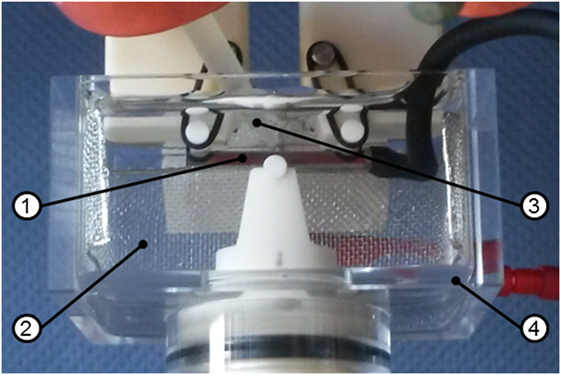
Figure 1. Set-up of the electrochemical cell for corrosion fatigue experiments, including the sample (1) as working electrode, a fine platinum mesh (2) as counter electrode, an agar salt bridge (3) connected to the saturated calomel electrode reference electrode and an acrylic glass container (4) filled with 0.01 M Na2SO4 + 0.01 M NaCl.
At first, three different stress amplitudes [σa = (σmax−σmin)/2 = 200, 400, and 600 MPa] for fatigue testing in corrosive medium were determined by reference tests in air. Afterward, a series of cyclic tests at free corrosion conditions with in situ measurements of the OCP was carried out. Furthermore, three diverse anodic potentials (−50, 0, and +50 mV vs. SCE) were chosen from potentiodynamic polarization curves determined for Vitreloy 105 in our testing electrolyte 0.01 M Na2SO4 + 0.01 M NaCl. These potential values are the same as those selected for our previous SCC experiments, and they are in the interval between ER and EP, where pitting corrosion is expected (Gostin et al., 2015a). For each combination of load level and applied anodic potential, three different samples were tested. Each sample was tested until either fracture occurred, or the runout limit of 107 loading cycles was reached. A comprehensive fractographic analysis of the tested samples as well as an investigation of the elemental distribution on the fracture surface by EDX was finally conducted.
Results and Discussion
Cyclic Bending Behavior in Air
In order to select three load levels for CF tests, the S–N curve of the bulk glassy Zr52.5Cu17.9Al10Ni14.6Ti5 alloy was determined in air (Figure 2). The black trend line characterizes the fatigue life of the tested Vitreloy 105 samples, and horizontal arrows denote runouts that endured more than 107 load cycles. It should be noted that the real fatigue strength of Vitreloy 105 was determined at σa = 315 MPa. When assuming an ultimate tensile strength of σUTS = 1,700 MPa [only determined for Vitreloy 105 under four-point bending conditions (Morrison et al., 2007b)], there is a normalized fatigue limit of σa/σUTS = 0.19. The load levels for later CF tests were chosen in order to cover an interval of number of cycles to fracture as wide as possible.
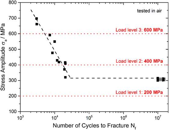
Figure 2. Determination of load levels for corrosion fatigue testing on Vitreloy 105; cyclic three-point bending tests were conducted in air at R = 0.1 and f = 50 Hz.
Therefore, the lowest stress amplitude was selected as σa = 200 MPa, thus significantly below the fatigue endurance limit and leading invariably to runouts, suggesting an observable effect of corrosion or corrosion–fatigue interactions in CF experiments. Stress amplitudes of σa = 400 MPa and σa = 600 MPa with 104 ÷ 2 × 10⁴ and 4 × 10³ ÷ 5 × 10³ cycles to fracture, respectively, were also chosen.
Fractographic analysis of samples fractured in air revealed characteristic features of Zr-based BMG fracture surfaces as also detected in Hess et al. (2006) and Morrison et al. (2007b). Figure 3 shows a representative fracture surface of the three-point bending fatigue samples. Cracks were found to initiate at the tensile stressed surface, especially at sample edges starting from small surface defects or sometimes at near-surface micropores that act as supplementary stress concentrators (not shown here). Stable crack growth occurred in the quarter-elliptic fatigue region that is characterized by fine striations (see red inset in Figure 3) that result from stepwise crack propagation along small shear bands arising in the plastic zone in front of the crack tip. However, crack propagation could not be correlated directly to striation spacing, which suggests that there is an accumulation of damage over several loading cycles as also reported by Liu et al. (2015). The area of fatigue crack growth covered between 6 and 35% of the whole fracture surface in the present study. After passing a sharp transition region, the crack propagates much faster until final fracture occurs. The resulting fast fracture region has a characteristic vein-like morphology, which is commonly observed in BMGs.
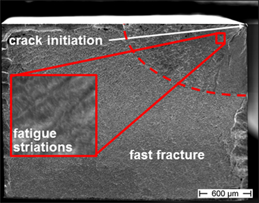
Figure 3. Typical fracture surface of a bar-shaped Vitreloy 105 sample after cyclic three-point bending at R = 0.1, f = 50 Hz, σa = 400 MPa, and Nf = 20,550 in air (tensile loaded surface is at the top, detailed view of striated fatigue region showed in red inset).
The large scatter in fatigue lifetimes during cyclic bending tests in air, mainly visible around the σa = 400 MPa load level, is explained by a varying sample quality. Fracture can be influenced by micropores with sizes up to 50 µm as well as by other material imperfections (e.g., unmolten particles). The formation of such defects during the suction casting process could not be avoided completely. Both features led to a shifting of the crack initiation site from the tensile-stressed surface to inner regions in some cases, and this could also be detected on the fracture surface.
Crack Growth Analysis by OCP Measurement
A previous work referred to the detection of the early stages of fracture/shear banding during quasi-static three-point bending of bulk glassy Zr52.5Cu17.9Ni14.6Al10Ti5 alloy samples by exploiting the high sensitivity of the OCP to surface changes for passivated surfaces (Grell et al., 2015). In our current study, such an OCP measurement was conducted under cyclic loading conditions to gain further information about the crack initiation point and the crack propagation mechanisms. Figure 4A shows one exemplary curve of the OCP signal plotted vs. the number of loading cycles. The sample was tested in 0.01 M Na2SO4 + 0.01 M NaCl under open circuit conditions at a stress amplitude of σa = 541 MPa. The fatigue life in electrolyte was similar to the one in air. This indicates that the electrolyte has a minimal influence on the crack propagation, and new bare metal surface created with each cycle passivates effectively. This is in agreement with the electrochemical behavior of this alloy, which has an OCP value below both its pitting and repassivation potential.
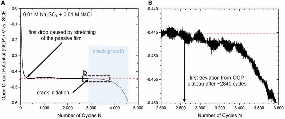
Figure 4. (A) Crack initiation and propagation correlated to an in situ OCP measurement during cyclic three-point bending at σa = 541 MPa and (B) detailed view of the earliest stage of crack initiation (black dashed box).
Before mechanical testing was started, the bending samples have been immersed in 0.01 M Na2SO4 + 0.01 M NaCl solution for 45–60 min until the changes in OCP were less than 2 mV/5 min. According to that, OCP was in a steady state (mean value from all tests ~165 mV vs. SCE) when the first loading cycle was applied. Since the mechanical pre-load to ensure exact positioning of the samples in the three-point mounting was set to only ~50% of the maximum stress prior to cyclic loading, there was a significant drop in OCP from −74 ± 5 mV vs. SCE to −445 ± 5 mV vs. SCE when the test started, and the maximum load was achieved for the first time. This effect is caused by a sudden stretching of the passive layer as a consequence of extended flexure on the tensile loaded surface. Subsequently, repassivation started and there is a slight but steady increase visible in the OCP curve. Because of the high sensitivity of the electrochemical set-up and as a result of small vibrations in the corrosion cell during cyclic loading, there is a little deviation in OCP until a significant plateau at −450 ± 10 mV is reached (see red dotted line in Figure 4A). Our results are also in good agreement with the observations of Morrison et al. (2007a) as the plateau levels are supposed to depend on the loading level. Cyclic testing at σa = 400 MPa led to a steady OCP value of −300 ± 10 mV vs. SCE, while testing at σa = 650 MPa generated an OCP value of −500 ± 10 mV vs. SCE. However, the first deviation from the stable plateau in terms of a smooth drop of the OCP is detected after 2,840 ± 10 loading cycles (see Figure 4B) for the presented sample. This drop indicates the earliest stage of crack initiation at the tensile-stressed sample surface. It can be assumed that the OCP changes immediately since in the crack region the bare metal surface is exposed to the electrolyte. A continuous decrease in OCP characterizes the following stable crack growth section (Figure 4A, marked in blue), which can be correlated to stable fatigue crack propagation detected by fine striations on the fracture surface. Further small drops in OCP are supposed to be related to locally increased crack growth velocity before crack tip blunting delays crack propagation. The OCP signal decreases until sample fracture after 4,530 ± 10 cycles, and therefore, the section of stable crack growth is suggested to be (4,530−2,840)/4,530 ≈ 37 ± 1% of the whole fatigue life. An additional analysis of the equivalent fracture surface (not shown here) reveals a fatigue crack region of 0.53 mm2 delivering a fraction of only 11 ± 1% with respect to the total cross section of 4.76 mm2. Furthermore, the rate of decrease (or the slope) of the OCP curve increases uniformly as expected in accordance with increasing crack growth velocity. As the stable crack growth regime determined by the OCP analysis is significantly larger than the fatigue fraction at the fracture surface, we suppose that the highly sensitive electrochemical response also considers early pre-damage stages of the passive film before active cracking sets in. Shear banding mechanisms prior to crack initiation might be a reasonable assumption, but there have to be carried out more detailed investigations for evaluation. Nevertheless, crack propagation analysis by measurement of the OCP is considered to be an appropriate method providing reliable results.
CF Tests under Anodic Polarization
As we have seen in the previous section, at open circuit conditions, no clear CF phenomena take place, and this was explained by the effective passivation of the crack tip and crack walls as OCP is below the repassivation potential. Therefore, in another set of experiments, a potential above the repassivation one was applied to the sample. The bar-shaped specimens have been immersed in 0.01 M Na2SO4 + 0.01 M NaCl solution, and OCP was recorded until it reached a stable value (mean value from all tests ~165 mV vs. SCE). Afterward, the anodic potential was applied. During the whole test, the responding current density was recorded to gather further information about crack initiation and crack propagation mechanisms as already shown for quasi-static bending in a previous study (Grell et al., 2015). Figure 5 shows an exemplary curve for a fatigue sample tested at an anodic potential of −50 mV vs. SCE at a stress amplitude of σa = 585 MPa. Current density is plotted against the number of loading cycles.
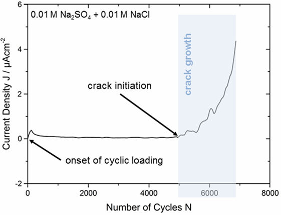
Figure 5. Crack initiation and propagation during anodic polarization at −50 mV in 0.01 M Na2SO4 + 0.01 M NaCl correlated with the current density response during cyclic three-point bending at σa = 585 MPa.
When applying a potential of −50 mV vs. SCE, the current density establishes at a nearly constant value slightly above 0 μAcm−2 due to almost equal cathodic and anodic currents as expected in a regime so close to the corrosion potential. This steady state was achieved after ~200 s, and mechanical loading was started subsequently. Due to the onset of cyclic loading, the current density shows a sharp peak (see Figure 5) and this is attributed to the stretching of the passive layer as described for the OCP measurements in Section “Crack Growth Analysis by OCP Measurement” above. This is followed by a continuous decrease until a second plateau is attained at ~0.2 μA cm−2. The current density remains at a nearly constant level, which is slightly above the value in the mechanically unloaded regime because the passive film is constantly altered by the cyclic stress. Since the scatter in the current density curve is very small, the point of passive film breakdown can be detected quite exactly after 4,880 ± 10 loading cycles. Thereby, the fatigue crack initiates at the tensile stressed sample surface and breaks the passive layer locally. Then, the current response starts to increase steadily as a result of stable crack propagation and related local metal dissolution. Several sudden current drops occur and these phenomena may be related to variations in the crack growth rate and short-term delay of crack propagation. Shear banding processes in the plastic zone in front of the crack tip are expected to cause crack tip blunting, and multiple shear bands can lead to changes of the crack path until the sample finally failed after 6,885 ± 10 loading cycles. Such a delayed crack growth was also detected for bainitic and martensitic steels by Suresh et al. (1981). They observed the generation of oxide films within the crack during mechanical testing at low loading ratios (R = 0.05) in moist atmospheres. In case of small crack tip opening displacements that are present especially at early fatigue fracture stages, these oxide layers lead to an earlier contact between both crack surfaces. As a consequence, the authors suggested a raise in the critical stress intensity factor Kc and a reduced effective ΔK in the crack tip region. Due to comparable testing conditions, a similar mechanism could be supposed in our current investigation on Zr-based bulk metallic glass. However, oxidization processes within the propagating crack as a result of repassivation events should be clearly detectable by drops in the current response (see stable crack growth regime in Figure 5). The fraction of stable fatigue crack propagation related to the number of cycles to failure is 29 ± 1% and thus ~21.6% lower than the fraction determined at comparable stresses by in situ OCP analysis in Section “Crack Growth Analysis by OCP Measurement.” However, it should be noted that fatigue life could be extended by more than 50% due to anodic polarization at −50 mV vs. SCE. The responsible mechanisms will be discussed later in the text.
An additional analysis of the fracture surface was conducted to gain further information about the damage mechanisms. As already shown in Section “Crack Growth Analysis by OCP Measurement” for the sample tested under open circuit conditions, the area of the (corrosion) fatigue region was measured and examined in relation to the total cross section of the bar-shaped specimen. The microscopically determined area ratio for the anodically polarized sample from Figure 5 was determined to be only 10 ± 1% and hence, significantly lower than the calculated fraction of 29 ± 1%, which was determined by the in situ current density measurement. This observation is in good accordance with the crack propagation analysis by OCP in Section “Crack Growth Analysis by OCP Measurement” and has to be related to supplementary damage mechanisms, e.g., shear banding, prior to crack initiation. The supposed mechanisms will be discussed later on the basis of scanning electron microscope (SEM) investigations.
Further tests at anodic potentials of 0 mV vs. SCE and +50 mV vs. SCE were conducted under cyclic three-point bending conditions, i.e., at higher potentials that are still in the EP–ER regime (Gostin et al., 2015a). In that context, the present research focusses on the interaction between mechanically and electrochemically induced fractures. Figure 6 exhibits the results of CF testing in 0.01 M Na2SO4 + 0.01 M NaCl. Thereby, three comparable tests were conducted for every anodic potential and stress amplitude in case of sample fracture or until two runouts (marked by horizontal arrows) were achieved. The dotted lines characterize only the trend of fatigue lives for the different testing conditions and are not very representative because of the restricted number of specimens and the low runout limit of 105 loading cycles.
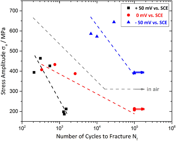
Figure 6. Anodic polarization at −50, 0, and +50 mV vs. SCE, during cyclic loading at various stress amplitudes in 0.01 M Na2SO4 + 0.01 NaCl solution.
The results in Figure 6 reveal a distinct influence of the stress level as well as of the applied anodic potential on the fatigue life of Vitreloy 105 and should be discussed in correlation with the fatigue behavior in air (see S–N curve in Figure 2). Although all three selected potentials are located in the anodic regime enabling pitting corrosion [all three potentials are higher than the repassivation potential, i.e., mean value−99 mV vs. SCE, SD 28 mV (Gostin et al., 2015a)], there seems to be a lifetime extending effect of the most negative potential, i.e., −50 mV vs. SCE, and an obviously degrading effect of 0 mV vs. SCE and +50 mV vs. SCE, which are closer to the critical pitting potential EP (Gostin et al., 2015a) compared to the results of the samples tested in air. The fine grading of the chosen potentials offers a much more explicit view on the electrochemical influence of fatigue life than the research of Morrison et al. (2007a) who distinguished only between anodic polarization at 100 mV vs. SCE and cathodic polarization at −900 mV vs. SCE in aqueous 0.6 M NaCl solution. Their research also detected an environmental degradation mechanism only at anodic potentials and concluded that anodic dissolution is responsible for the negative effect. That assumption is in good accordance with the results of our recent CF reference tests in halide-free 0.01 M Na2SO4 solution, where no negative effect on fatigue life could be detected. So, we consider the increased pitting propensity in presence of chloride ions to be the driving force during crack propagation.
Our results reveal a mean number of cycles to failure of 18,290 ± 10 in air, 375 ± 10 cycles at +50 mV vs. SCE, 1,234 ± 10 cycles at 0 mV vs. SCE, and two runouts for −50 mV vs. SCE (all tests around σa = 400 MPa). Therefore, a superimposed effect of both anodic dissolution and repassivation processes at the crack tip is suggested to influence CF behavior of Vitreloy 105 essentially with the predominant effect depending on the selected anodic potential. Consequently, −50 mV vs. SCE is slightly more noble than the repassivation potential ER = −99 mV vs. SCE meaning a lower tendency to anodic dissolution and increased repassivation tendency preventing the sample from fracture within 105 loading cycles. The fact that even longer fatigue lifetimes than in air were detected at −50 mV vs. SCE could be explained by an oxide-induced crack closure, which was already described above (Suresh et al., 1981). Whereas, anodic polarization at +50 mV vs. SCE is passing closer to the pitting potential of EP = 297 mV vs. SCE and reinforces the creation of corrosion pits and anodic dissolution. An anodic potential of 0 mV vs. SCE seems to have also a degrading effect on the fatigue life at σa = 400 MPa as it reduces the number of cycles to failure to 6.7% compared to samples tested in air. The ER and EP values are adopted from our previous paper on SCC of Vitreloy 105 in the same chloride-containing electrolyte (Gostin et al., 2015a). At an elevated load level of σa = 600 MPa for the −50 mV vs. SCE polarized samples, the fatigue lifetime is 15,110 ± 10 cycles (average value), which is five times longer than in air. However, the mean fatigue lifetime in non-halide 0.01 Na2SO4 solution under open circuit conditions is 2,560 ± 10 cycles and, therefore, slightly below the fatigue life in air. Consequently, the applied potential of −50 mV vs. SCE seems to have a further beneficial effect on the forming of the presumed oxide layer within the crack. At σa = 200 MPa, all non-polarized samples passed the limit of 105 cycles while anodic polarization at +50 mV vs. SCE caused failure after 1,380 ± 10 cycles due to intense anodic dissolution processes. The damage-provoking mechanisms are suspected to be mechanically as well as corrosion driven. This should be clarified by a comprehensive SEM analysis with additional EDX in the following part of the manuscript.
Fractographic Analysis
Besides the bending fatigue samples tested in air, which showed the characteristic features on their fracture surfaces (see Figure 3), the polarized samples have also been investigated by SEM. The observed fractographic characteristics are presented exemplarily in Figure 7 on a CF sample tested at σa = 388 MPa and an anodic potential of 0 mV vs. SCE.
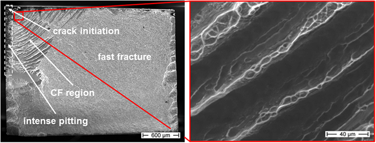
Figure 7. Fracture surface of a corrosion fatigue (CF) sample tested at an anodic potential of 0 mV, σa = 388 MPa, and Nf = 2,616, in 0.01 M Na2SO4 + 0.01 M NaCl (tensile loaded surface is at the top, detailed view of striated corrosion fatigue region showed in red inset).
The main features are comparable to those observed for the non-polarized samples indicating a clear crack initiation site, a presumably quarter-elliptic (corrosion) fatigue region, and a large fast fracture area with significant cleavage near to the left and right sample edges. Especially the tensile stressed surface areas in the upper left of Figure 7 exhibit intense pitting corrosion in terms of dark areas near the sample surface (marked by white dotted box). The pits which are detected as dark areas can reach up to ~150 μm into the sample. While the fast fracture region is characterized by the typical vein-like morphology (not shown here in higher magnification), the CF striations appear much broader than the striations generated under open circuit conditions or in air. The red inset in Figure 7 gives a representative and more detailed image of typical CF striations. Alternating smooth dark regions and brighter areas with vein-like structures offer interesting information about the related CF fracture mechanisms. The striation spacing increases from the crack initiation site to the fast fracture transition area. In consequence of these observations, there are two possible mechanisms suggested that are interfering with each other during anodic polarization and simultaneous cyclic loading. The smooth areas of the broad striated CF region may result from anodic dissolution and related cleavage along shear bands while the vein-like morphology might be caused by abrupt fast fracture. Besides the samples tested at 0 mV vs. SCE also those tested at +50 mV vs. SCE revealed those broader striations than in air consisting of alternating smooth and vein-like areas. In contrast, an anodic polarization at −50 mV vs. SCE led to fracture surfaces comparable to those in air with a lack of these broad striations. A subsequent investigation of the elemental distribution could contribute to the clarification of the involved processes (later in the text).
The pitting corrosion behavior of Zr-based BMGs in chloride-containing solutions has been widely investigated and is well understood so far (Mudali et al., 2004; Gebert et al., 2010, 2012; Gostin et al., 2015b). As already shown in Figure 7, cracks start preferentially at corrosion pits on the tensile loaded surface. Therefore, the sample surface of a polarized sample (+50 mV vs. SCE) was analyzed by EDX after fracture. One characteristic corrosion pit which was located near to the fracture surface is presented in Figure 8 (left). Since the polished sample surface showed no visible imperfections before mechanical testing, there was an initial breakdown of the brittle passive film as a consequence of the continuous flexural stresses and a small generated slip step. At this site, chloride-induced pitting might be favored. This assumption is supported by Gebert et al. (2012) who investigated the influence of mechanically generated defects on corrosion behavior of Zr59Ti3Cu20Al10Ni8 alloy in aqueous chloride-containing solutions. Their work reveals that shear banding takes place preferentially at corrosion pits, and conversely pitting is more likely at shear bands. In our case, there is bare metal exposed to the chloride-containing electrolyte when sudden rupture of the passive layer occurs. Furthermore, the start of cracking and the resulting increase in current response was in good accordance with a starting increase of the mechanical displacement, which was recorded during cyclic testing (not shown here). At an applied anodic potential of +50 mV vs. SCE that was supposed to reinforce anodic dissolution, the less noble components of Vitreloy 105, i.e., mainly Al and Zr, start dissolving immediately due to an auto-catalytic reaction with chloride anions as reported by Mudali et al. (2004). The elemental distribution of the corrosion pit in Figure 8 (left) shows not only a slight depletion of Zr in the central ground of the pit but also some enrichment of this component at the inner rim. In contrast, there is a significant enrichment in Cu and Ni at the bottom of the pit that is also in good accordance with the observations in Mudali et al. (2004) because they attributed the local dissolution and immediate re-deposit of copper to the generation of the porous structure.
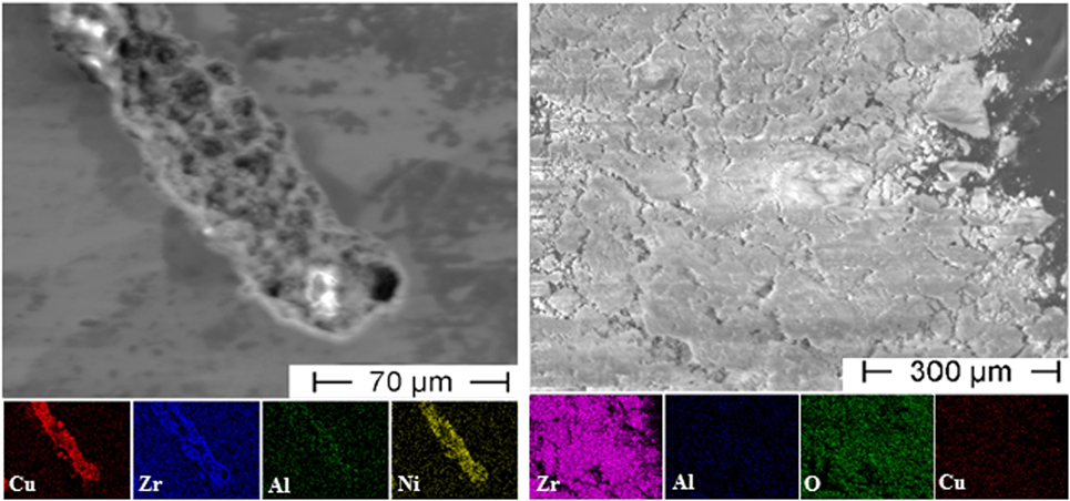
Figure 8. Energy dispersive X-ray analysis of a corrosion pit at the side surface of the bending sample (left) and of the dissolved material extracted from the electrolyte as powder after testing (right).
The onset of anodic dissolution could be determined easily during CF testing under potentiostatic control. Characteristic corrosion products developed at the crack tip and spread out quickly. After the experiment, it was possible to gather the dissolved material in form of fine powder at the bottom of the electrochemical cell and to extract it from the residual electrolyte. This powder was investigated by EDX as well, and the results are shown in Figure 8 (right). As expected, it consists basically of Zr and O while only traces of Cu could be detected. However, the fraction of Al seems to be smaller than expected due to the results from the corrosion pit, but this element could be detected poorly overall.
CF Cracking Model
All results from this study were summarized to establish the following model for CF cracking of bulk amorphous Vitreloy 105 under anodic polarization conditions. Since the damage mechanisms are still not completely understood in detail, the proposed model should offer a first approach as a basis for further studies on CF of BMGs. Though the model can be accounted in analogy to the previously published work on SCC by Gostin et al. (2015a).
(1) Corrosion pits nucleate at the tensile loaded surface, preferentially at local breakdown sites of the passive layer, which is formed mainly by Zr- and Al-oxide or rarely at small surface defects, e.g., scratches or micropores. Furthermore, pits tend to initiate randomly along the sample edges acting as stress concentrators.
(2) Corrosion pits grow due to anodic dissolution of the less noble components of the alloy (mainly Zr and Al) until the critical pit size for crack initiation is achieved and CF cracking starts.
(3) Shear bands initiate in front of the crack tip leading to a reduced stress concentration and delayed but step-wise crack propagation.
(4) Anodic dissolution takes place preferentially at the shear bands as described in Gebert et al. (2012) and cleavage is enforced. The resulting areas on the fracture surface are smooth, and EDX analysis revealed Zr (and Al) depletion indicating a dissolution-related mechanism.
(5) Due to the increased crack length, there is a higher stress intensity at the crack tip that simplifies shear band initiation again and causes short-time crack propagation. Thereby, the vein-like structures are formed until crack propagation is stopped by further anodic dissolution along the shear band.
(6) The described process repeats several times until the critical stress intensity is attained because of the continuously increased crack length. The stepwise crack propagation leads to the characteristic broad striated fracture surface in the regime of stable crack growth.
According to the applied potential, repassivation processes seem to play also an important role in delaying fracture. Anodic polarization at −50 mV vs. SCE [that is near the repassivation potential ER = −99 mV vs. SCE for the given alloy/electrolyte system (Gostin et al., 2015a)] is suggested to support repassivation processes at the crack tip and thus to impede anodic dissolution at the same time. Furthermore, there is a possible mechanisms based on oxide-induced crack closure that was determined in a study on steels (Suresh et al., 1981). They observed the generation of oxide films within the crack during mechanical testing at low loading ratios (R = 0.05) in moist atmospheres. In case of small crack tip opening displacements, which are present especially at early fatigue fracture stages, these oxide layers lead to an earlier contact between both crack surfaces. As a consequence, the authors suggested a raise in the critical stress intensity factor Kc and a reduced effective ΔK in the crack tip region. This might also explain the increased fatigue life and delayed cracking in our experiments in electrolyte compared to the results obtained in air. In any case, it should be noted that both mechanisms, crack re-sharpening by anodic dissolution, and crack tip blunting by shear banding, contribute to crack propagation in CF testing. While samples being anodically polarized at −50 mV vs. SCE exhibit significantly improved fatigue properties, anodic polarization at 0 mV vs. SCE and +50 mV vs. SCE leads to a dramatic reduction in fatigue lifetime of Vitreloy 105.
Conclusion
The cyclic three-point bending properties of a bulk glassy alloy, i.e., Zr52.5Cu17.9Al10Ni14.6Ti5 (Vitreloy 105), were investigated in air, at open circuit conditions, and under anodic potentiostatic control. Three potential values between the repassivation and the pitting potential in 0.01 M Na2SO4 + 0.01 M NaCl solution were chosen. The following conclusions were drawn:
1. The S–N curve was determined under cyclic three-point bending conditions at R = 0.1 in air, and the highest fatigue endurable stress amplitude is σa = 315 MPa;
2. Crack initiation and the region of stable crack growth can be correlated to the current response at anodic potentiostatic control and to OCP under free corrosion conditions;
3. Pitting takes place only at anodic potentials of 0 mV vs. SCE and +50 mV vs. SCE and the pits form preferentially at sample edges, but randomly along any of the edges;
4. The pits reveal a slight depletion of Zr and Al as well as an enrichment of Cu and Ni in the central ground;
5. Fatigue life is extended about five times at an anodic potential of −50 mV vs. SCE, which is close to the repassivation potential ER of Vitreloy 105 in 0.01 M Na2SO4 + 0.01 M NaCl solution, compared to the fatigue life in air;
6. Anodic dissolution-related crack propagation with significant alternating smooth and vein-like fracture features (resulting in broad striations) are only detectable at 0 mV vs. SCE and +50 mV vs. SCE.
A mechanism for CF cracking is proposed, but there is still a lack of detailed information about the crack initiation and crack propagation processes, so that further investigations on this topic should contribute to a comprehensive understanding in the future.
Author Contributions
DG planned the experiments and mainly evaluated the results. He was also acting as corresponding author who mainly developed the structure and content of the manuscript. YW carried out most of the experiments and SEM analysis. PG contributed to the development of the experimental setup and the interpretation of the results. AG was involved in developing the structure of the manuscript, and she contributed to the discussion of the results. EK was involved in developing the structure of the manuscript, and he contributed to the discussion of the results.
Conflict of Interest Statement
The authors declare that the research was conducted in the absence of any commercial or financial relationships that could be construed as a potential conflict of interest.
Acknowledgments
DG wishes to acknowledge David Geißler for fruitful discussions. The authors thank Sven Donath and Michael Frey for sample preparation. Financial support for this work was provided by the German Research Society (DFG) under grant numbers KE 1426/4-1 and GE 1106/11-1/2 in the frame of the PP 1594 collaborative project.
References
Ashby, M. F., and Greer, A. L. (2006). Metallic glasses as structural materials. Scr. Mater. 54, 321–326. doi:10.1016/j.scriptamat.2005.09.051
Gebert, A., Gostin, P. F., and Schultz, L. (2010). Effect of surface finishing of a Zr-based bulk metallic glass on its corrosion behaviour. Corros. Sci. 52, 1711–1720. doi:10.1016/j.corsci.2010.01.027
Gebert, A., Gostin, P. F., Uhlemann, M., Eckert, J., and Schultz, L. (2012). Interactions between mechanically generated defects and corrosion phenomena of Zr-based bulk metallic glasses. Acta Mater. 60, 2300–2309. doi:10.1016/j.actamat.2011.12.044
Gebert, A., Ismail, N., Wolff, U., Uhlemann, M., Eckert, J., and Schultz, L. (2002). Effects of electrochemical hydrogenation of Zr-based alloys with high glass-forming ability. Intermetallics 10, 1207–1213. doi:10.1016/S0966-9795(02)00134-6
Gostin, P. F., Eigel, D., Grell, D., Uhlemann, M., Kerscher, E., Eckert, J., et al. (2015a). Stress corrosion cracking of a Zr-based bulk metallic glass. Mater. Sci. Eng. A 639, 681–690. doi:10.1016/j.msea.2015.05.049
Gostin, P. F., Eigel, D., Grell, D., Eckert, J., Kerscher, E., and Gebert, A. (2015b). Comparing the pitting corrosion behavior of prominent Zr-based bulk metallic glasses. J. Mater. Res. 30, 233–241. doi:10.1557/jmr.2014.371
Grell, D., Gostin, P. F., Eckert, J., Gebert, A., and Kerscher, E. (2015). In situ electrochemical analysis during deformation of a zr-based bulk metallic glass: a sensitive tool revealing early shear banding. Adv. Eng. Mater. 17, 1532–1535. doi:10.1002/adem.201500273
Hasegawa, M., Kotani, K., Yamaura, S., Kato, H., Kodama, I., and Inoue, A. (2004). Hydrogen-induced internal friction of Zr-based bulk glassy alloys in a rod shape above 90 K. J. Alloys Comp. 365, 221–227. doi:10.1016/S0925-8388(03)00686-8
Hess, P. A., Menzel, B. C., and Dauskardt, R. H. (2006). Fatigue damage in bulk metallic glass II: experiments. Scr. Mater. 54, 355–361. doi:10.1016/j.scriptamat.2005.10.007
Inoue, A., and Takeuchi, A. (2011). Recent development and application products of bulk glassy alloys. Acta Mater. 59, 2243–2267. doi:10.1016/j.actamat.2010.11.027
Ismail, N., Gebert, A., Uhlemann, M., Eckert, J., and Schultz, L. (2001). Effect of hydrogen on Zr65Cu17.5Al7.5Ni10 metallic glass. J. Alloys Comp. 314, 170–176. doi:10.1016/S0925-8388(00)01211-1
Kruzic, J. J. (2011). Understanding the problem of fatigue in bulk metallic glasses. Metall. Mater. Trans. A 42, 1516–1523. doi:10.1007/s11661-010-0413-1
Launey, M. E., Hofmann, D. C., Johnson, W. L., and Ritchie, R. O. (2009). Solution to the problem of the poor cyclic fatigue resistance of bulk metallic glasses. Proc. Natl. Acad. Sci. U.S.A. 106, 4986–4991. doi:10.1073/pnas.0900740106
Li, J. X., Wang, Y. W., Shan, G. B., Qiao, L. J., and Chu, W. Y. (2013). Study of Hydrogen-Induced Plastic Deformation in Bulk Metallic Glass. Beijing: Department of Materials Physics, University of Science and Technology.
Liu, Y., Wang, Y.-M., and Liu, L. (2015). Fatigue crack propagation behavior and fracture toughness in a Ni-free ZrCuFeAlAg bulk metallic glass. Acta Mater. 92, 209–219. doi:10.1016/j.actamat.2015.04.003
Lund, A. C., and Schuh, C. A. (2004). The Mohr-Coulomb criterion from unit shear processes in metallic glass. Intermetallics 12, 1159–1165. doi:10.1016/j.intermet.2004.07.001
Mattern, N., and Gebert, A. (2003). Hydrogenation of Zr60Ti2Cu20Al10Ni8 bulk metallic glass. Appl. Phys. Lett. 83, 1134–1135. doi:10.1063/1.1600836
Menzel, B. C., and Dauskardt, R. H. (2006). Stress-life fatigue behavior of a Zr-based bulk metallic glass. Acta Mater. 54, 935–943. doi:10.1016/j.actamat.2005.10.021
Morrison, M. L., Buchanan, R. A., Liaw, P. K., Green, B. A., Wang, G. Y., Liu, C. T., et al. (2007a). Corrosion-fatigue studies of the Zr-based Vitreloy 105 bulk metallic glass. Mater. Sci. Eng. A 467, 198–206. doi:10.1016/j.msea.2007.03.106
Morrison, M. L., Buchanan, R. A., Liaw, P. K., Green, B. A., Wang, G. Y., Liu, C. T., et al. (2007b). Four-point-bending-fatigue behavior of the Zr-based Vitreloy 105 bulk metallic glass. Mater. Sci. Eng. A 467, 190–197. doi:10.1016/j.msea.2007.05.066
Mudali, U. K., Baunack, S., Eckert, J., Schultz, L., and Gebert, A. (2004). Pitting corrosion of bulk glass-forming zirconium-based alloys. J. Alloys Comp. 377, 290–297. doi:10.1016/j.jallcom.2004.01.043
Nakai, Y., and Yoshioka, Y. (2010). Stress corrosion and corrosion fatigue crack growth of Zr-based bulk metallic glass in aqueous solutions. Metall. Mater. Trans. A 41, 1792–1798. doi:10.1007/s11661-009-9945-7
Naleway, S. E., Greene, R. B., Gludovatz, B., Dave, N., Ritchie, R. O., Kruzic, J. J., et al. (2013). Resistant Zr-based bulk metallic glass. Metall. Mater. Trans. A 44, 5688–5693. doi:10.1007/s11661-013-1923-4
Ritchie, R. O., Schroeder, V., and Gilbert, C. J. (2000). Fracture, fatigue and environmentally-assisted failure of a Zr-based bulk amorphous metal. Intermetallics 8, 469–475. doi:10.1016/S0966-9795(99)00155-7
Schroeder, V., Gilbert, C. J., and Ritchie, R. O. (1999). Effect of aqueous environment on fatigue-crack propagation behavior in a Zr-based bulk amorphous metal. Scr. Mater. 40, 1057–1061. doi:10.1016/S1359-6462(99)00067-6
Schroeder, V., and Ritchie, R. O. (2006). Stress-corrosion fatigue–crack growth in a Zr-based bulk amorphous metal. Acta Mater. 54, 1785–1794. doi:10.1016/j.actamat.2005.12.006
Scully, J. R., Gebert, A., and Payer, J. H. (2007). Corrosion and related mechanical properties of bulk metallic glasses. J. Mater. Res. 22, 302–313. doi:10.1557/jmr.2007.0051
Scully, J. R., and Lucente, A. (2005). “Corrosion of amorphous metals,” in ASM Handbook (Materials Park, OH: ASM International), 476–489.
Shan, G. B., Wang, Y. W., Chu, W. Y., Li, J. X., and Hui, X. D. (2005). Hydrogen damage and delayed fracture in bulk metallic glass. Corros. Sci. 47, 2731–2739. doi:10.1016/j.corsci.2004.07.045
Suh, D., and Dauskardt, R. H. (2000). Hydrogen effects on the mechanical and fracture behavior of a Zr-Ti-Ni-Cu-Be bulk metallic glass. Scr. Mater. 42, 233–240. doi:10.1016/S1359-6462(99)00337-1
Suh, D., and Dauskardt, R. H. (2001). Effects of pre-charged hydrogen on the mechanical and thermal behavior of Zr-Ti-Ni-Cu-Be bulk metallic glass alloys. Mater. Trans. JIM 42, 638–641. doi:10.2320/matertrans.42.638
Suresh, S., Zamiski, G. F., and Ritchie, R. O. (1981). Oxide-induced crack closure: an explanation for near-threshold corrosion fatigue crack growth behavior. Metall. Trans. A 12A, 1435–1443. doi:10.1007/BF02643688
Trexler, M. M., and Thadhani, N. N. (2010). Mechanical properties of bulk metallic glasses. Prog. Mater. Sci. 55, 759–839. doi:10.1016/j.pmatsci.2010.04.002
Vargonen, M., Huang, L., and Shi, Y. (2012). Evaluating Mohr-Coulomb yield criterion for plastic flow in model metallic glasses. J. Non Cryst. Solids 358, 3488–3494. doi:10.1016/j.jnoncrysol.2012.05.021
Wang, Y. W., Chu, W. Y., Li, J. X., Hui, X. D., Wang, Y. B., Gao, K. W., et al. (2004). In situ observation of hydrogen-enhanced localized plastic flow in Zr-based bulk metallic glass. Mater. Lett. 58, 2393–2396. doi:10.1016/j.matlet.2004.02.014
Wiest, A., Wang, G., Huang, L., Roberts, S., Demetriou, M. D., Liaw, P. K., et al. (2010). Corrosion and corrosion fatigue of Vitreloy glasses containing low fractions of late transition metals. Scr. Mater. 62, 540–543. doi:10.1016/j.scriptamat.2009.12.025
Keywords: bulk amorphous alloys, corrosion fatigue, mechanical characterization, fracture, shear bands
Citation: Grell D, Wilkin Y, Gostin PF, Gebert A and Kerscher E (2017) Corrosion Fatigue Studies on a Bulk Glassy Zr-Based Alloy under Three-Point Bending. Front. Mater. 3:60. doi: 10.3389/fmats.2016.00060
Received: 29 September 2016; Accepted: 19 December 2016;
Published: 09 January 2017
Edited by:
Lothar Wondraczek, University of Jena, GermanyReviewed by:
Dongchan Jang, KAIST (Korea Advanced Institute of Science & Technology), South KoreaMaria Jesus Pascual, Spanish National Research Council, Spain
Copyright: © 2017 Grell, Wilkin, Gostin, Gebert and Kerscher. This is an open-access article distributed under the terms of the Creative Commons Attribution License (CC BY). The use, distribution or reproduction in other forums is permitted, provided the original author(s) or licensor are credited and that the original publication in this journal is cited, in accordance with accepted academic practice. No use, distribution or reproduction is permitted which does not comply with these terms.
*Correspondence: Daniel Grell, daniel.grell@mv.uni-kl.de