Edge Waves and Localization in Lattices Containing Tilted Resonators
 Domenico Tallarico
 Alessio Trevisan
 Natalia V. Movchan
 Alexander B. Movchan
- 1Department of Mathematical Sciences, University of Liverpool, Liverpool, United Kingdom
- 2EnginSoft SPA, Padova, Italy
The paper presents the study of waves in a structured geometrically chiral solid. A special attention is given to the analysis of the Bloch-Floquet waves in a doubly periodic high-contrast lattice containing tilted resonators. Dirac-like dispersion of Bloch waves in the structure is identified, studied, and applied to wave-guiding and wave-defect interaction problems. The work is extended to the transmission problems and models of fracture, where localization and edge waves occur. The theoretical derivations are accompanied with numerical simulations and illustrations.
1. Introduction
We introduce a novel concept of a multi-scale shield/filter, which couples pressure waves and rotational motion in an elastic lattice. Such a structure incorporates high-contrast tilted resonators, and their dynamic response is linked to the rotational wave forms.
The interest in elastic waves in chiral media is high, as reflected by the series of papers on micro-structured media, which incorporate active gyroscopes (Brun et al., 2012; Carta et al., 2014, 2017; Süsstrunk and Huber, 2015; Wang et al., 2015; Huber, 2016). Waves in such periodic structures possess fascinating, sometimes counter-intuitive, properties. These include filtering, polarization, as well as directional preference and/or localization.
The present paper, in contrast with (Brun et al., 2012; Carta et al., 2014, 2017), deals with the lattice that does not include any active chiral mechanical elements, such as gyroscopic inclusions and a gyroscopic foundation. However, the geometry of the multi-structure considered here is chiral, and this, in turn, contributes to the coupling between the pressure and shear waves, which is supported by the lattice. The Bloch-Floquet waves in doubly periodic structures with tilted lattice resonators, and their dispersion properties, were studied in Tallarico et al. (2017). Other geometrically chiral lattices were studied in Spadoni et al. (2009), Liu et al. (2011, 2012), Spadoni and Ruzzene (2012), and Bigoni et al. (2013) in the continuum approximation. When dealing with effective properties of periodic media, high-frequency homogenization techniques (Craster et al., 2010, 2013; Movchan and Slepyan, 2014; Colquitt et al., 2015) can be used.
The notion of the multi-scale multi-structure (Kozlov et al., 1999) was used in Bigoni et al. (2013) to approximate the frequencies of standing waves of a multi-scale periodic structure with resonators, consisting of disks connected with the ambient medium by thin ligaments. In particular, the issue of degeneracies was noted for configurations of resonators with special inclinations of the thin ligaments.
The influence of the micro-structure on a dynamic crack in a lattice was discussed in Colquitt et al. (2012), Carta et al. (2013), and Trevisan et al. (2016). For a transient propagating crack, the crack edge emanates waves, which interact with the ambient medium. Even in subsonic regimes, the problem of a crack advancing in a micro-structured solid is a challenge. Analytical approaches applicable to cracks propagating at an average constant speed were presented in Slepyan (2002).
We draw the attention of the reader to the papers (Süsstrunk and Huber, 2015; Wang et al., 2015; Huber, 2016), which addressed the formation of unidirectional edge waves in active chiral elastic systems by achieving time-reversal symmetry breaking.
In the present work, we give a special attention to micro-structured solids containing cracks, and we show how a coating, built of a tilted resonator lattice, can absorb vibrations or otherwise can channel the energy away from the crack tip.
An adaptive finite element computation has been performed to model a transient propagation of a crack inside a channel of the micro-structured material. The earlier work (Trevisan et al., 2016) has addressed the question of a transient advance of a crack subjected to a dynamic load. The influence of a geometrically chiral multi-scale lattice on the field around the crack is demonstrated in the present paper.
An additional focus of this paper is on the effect of geometric chirality on the edge waves propagating along structured interfaces. In this context, we would like to mention the earlier work (Joseph and Craster, 2013) where asymptotics for elastic waves propagating along line defects in triangular and square lattices were investigated. Here we analyze waves around a “coated” crack, where the coating is introduced as a multi-scale structure of tilted resonators. We show examples of dynamic localization and edge waves.
The structure of the paper is as follows. The formulation of the problem and an outline of the dispersion properties of the Bloch-Floquet waves in a lattice with tilted resonators are included in Section 2. Wave localization and edge states are discussed in Section 3. In Section 4, we model a crack in a triangular lattice, surrounded by a structured coating containing tilted resonators. In Section 5, we study an edge crack sandwiched between two strips of resonators and subjected to a pulsating thermal load. The advance of the crack is studied in the transient regime. In Section 6, we draw our main conclusions.
2. Bloch-Floquet Waves in a Triangular Lattice with Tilted Resonators
In this section, we refer to the earlier paper (Tallarico et al., 2017) and give an outline describing the propagation of Bloch-Floquet waves in a triangular lattice with tilted rotational resonators. A schematic representation of the triangular lattice with resonators (TLR) is given in Figure 1A. Here, we demonstrate that the Bloch-Floquet frequency dispersion surfaces for the TLR can exhibit Dirac-like dispersion. Dirac-like dispersion arises from the triple degeneracy of two conical bands and one flat band, as also stated in Mei et al. (2012). In contrast, the pure Dirac dispersion is represented by a conical surface, incorporating two cones above and below the common vertex, called the “Dirac point.” Such dispersion surfaces are observed, for example, for lattices of high order of symmetry, such as graphene. Dirac-like dispersion can be achieved via the fine tuning of the unit cell’s eigenvalues in a plethora of phononic and photonic metamaterials. Dirac-like phononic lattices remain highly attractive because of their interesting physical properties: dynamic neutrality has recently been observed in a platonic crystal (Smith et al., 2014; Haslinger et al., 2017). Perfect transmission and tunneling were reported in Li and Mei (2015), which focused on a photonic crystal governed by the Helmholtz wave equation and exhibiting Dirac-like dispersion.
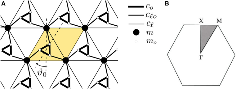
Figure 1. (A) A schematic representation of the triangular elastic lattice containing resonators, tilted by an angle ϑ0; the unit cell of the lattice is highlighted in yellow. (B) The first Brillouin zone for the triangular lattice and irreducible fraction (gray-shaded region).
2.1. Governing Equations
We consider an elastic triangular lattice (TL) containing tilted rotational resonators, as the one represented in Figure 1A. Point-wise masses m (black full circles) are considered at the triangular lattice nodes in Figure 1A, the lattice vectors being
where L is the distance between nearest neighbors. Figure 1B shows the first Brillouin zone of the TL, together with its irreducible part (gray area). The high-symmetry points are
The nodal points of the lattice whose mass is m are linked to each other by non-flexible, massless, extensible rods (thin lines) of longitudinal stiffness . The unit cell of the lattice (semitransparent yellow region in Figure 1A) contains a resonator, an equilateral triangle of side ℓ with point masses mo attached to its vertices (empty circles in Figure 1A). The vertices of the resonators are linked to the nodal points of the TL by non-flexible, extensible rods of longitudinal stiffness (medium-thickness black lines in Figure 1A). In this paper, the resonators are assumed to be rigid, i.e., the longitudinal stiffness co of the links connecting the vertices of the resonators is such that and . The resonators are tilted with respect to the external triangular lattice by an angle ϑ0, marked in Figure 1A.
We now give some geometric definitions useful to represent the dispersion equation for the triangular lattice with resonators. We denote by , i = {1, 2, 3}, the position vector of the ith mass relative to the center of mass , where “T” denotes transposition. The explicit expression is
where ϑ0 is the tilting angle, , and
is the clockwise rotation matrix. The vector linking the triangular lattice to the ith mass of the resonator in the reference cell n = 0 is
where , b has been introduced in equation (3) and the matrix is given in equation (3). Given the set of vectors (1) and (5), we introduce the corresponding projector matrices
The notation vuT in equation (6) is used to denote the dyadic product v ⊗ u of two vectors u and v.
We consider time-harmonic elastic Bloch-Floquet waves propagating through the lattice. Following Tallarico et al. (2017), the Bloch-Floquet displacement wave’s amplitude with Bloch vector k is
where the vectors quantities and are the in-plane displacements of the TL nodal points and of the center of mass of the resonators, respectively. In equation (7), ϑ(k) represents the angular displacement with respect to the equilibrium ϑ0. In the time-harmonic regime, the equations of motion in the lattice characterized by the displacement (7) have the matrix form
where ω is the Bloch-Floquet radian frequency and the vector Uk is given in equation (7). The inertia matrix that appears in equation (8) is
where M = 3mo is the total mass of the resonator, is its moment of inertia, and m is the mass of the nodal points of the triangular lattice. In Tallarico et al. (2017), it has been shown that the stiffness matrix in equation (8) is
where φ1(k) = exp(−k ⋅ t2), φ2(k) = exp(−k ⋅ t1), φ3(k) = 1, and . Consider the 3 × 3 block independent of k that appears in equation (10). We observe that
where is the 2 × 2 identity matrix. The diagonal matrix (11) is the stiffness matrix for a single resonator for which the natural frequencies squared are (Tallarico et al., 2017)
In equation (12), Ωcm is the frequency of oscillation of the center of mass of a single resonator, whereas the frequency Ωϑ describes the harmonic rotation of the resonator.
2.2. Triple Eigenvalue and Dirac-Like Dispersion Surfaces near k = 0
The elastic Bloch-Floquet waves in the doubly periodic structure of tilted resonators have interesting dispersion properties shown in Figure 2. A special feature is the Dirac-like cone with the vertex corresponding to k = 0, which is the main focus of this paragraph. Seeking non-trivial solutions for equation (8) requires
whose roots ω vs k determine the dispersion of Bloch waves (see, e.g., Figure 2). At k = 0, the roots of the fifth-degree in Ω = ω2 polynomial equation (13) can be found in their closed forms. Introducing the notation , with i the index of the root, we find
where Ωcm and Ωϑ have been introduced in equation (12). The first and second eigenvalues in equation (14) have multiplicity two, and the third one has multiplicity one. The geometric conditions
guarantee that the trusses do not cross each another. We observe that it is possible to obtain a triple eigenvalue corresponding to , if there exists
with and . We observe that
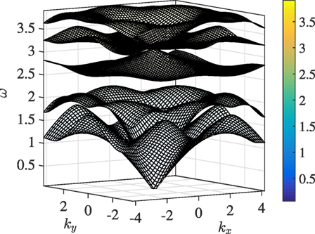
Figure 2. The Bloch-Floquet dispersion surfaces for a triangular lattice with resonators whose lattice parameters are listed in set 1 of Table 1. The color scale represents Bloch-Floquet frequencies ω.
The substitution of the expression (16) for mo into the Bloch frequencies at Γ in equation (14) gives the frequency squared for the triple eigenvalue
which is a positive quantity if the condition on and ϑ0 of equation (17) is satisfied.
Figure 3A represents the frequency dispersion surfaces for a TLR as a function of a set of Bloch wave vectors that comprise the first Brillouin zone (see Figure 1B). The lattice parameters have been chosen in such a way that equation (16) is satisfied. This implies the occurrence of a triple eigenvalue at Γ, as it can be seen by direct inspection of the optical part of the dispersion diagram. Specifically, we choose and ϑ0 = 0.82, which gives . Moreover, we fix and m = 0.8, which influences the maximum frequency of the acoustic modes. Finally, the choice guarantees that the frequency of the triple eigenvalue (18) is
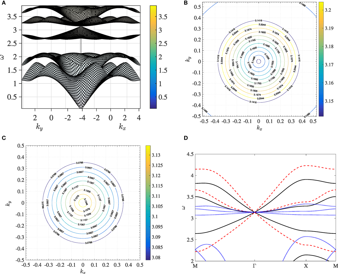
Figure 3. In panel (A), a side view of Figure 2 is provided. Panels (B,C) are slowness contours of panel (A). The frequencies represented here lie just above panel (B) and just below panel (C) ω = π, corresponding to the Dirac-like point. The color scale represents Bloch-Floquet frequencies ω. Panel (D) shows the dispersion curves of the optical modes for three set of lattice parameters. The solid black lines correspond to the lattice parameters used in panel (A); red dashed lines and blue dotted lines correspond to “set 2” and “set 3” in Table 1, respectively.
Figures 3B,C show the slowness contours of Figure 3A around the triple eigenvalue’s frequency ω = π. Figures 3B,C refers to frequencies just above and just below ω = π, respectively. Figures 3B,C show that the dispersion in the vicinity of the triple eigenvalue is isotropic. In Figure 3D, we compare along the path MΓXM the optical branches of three different TLRs whose lattice parameters are listed in Table 1. The black solid line refers to set 1 in Table 1 which has been already used in Figure 3A. Hence, the dispersion around the triple eigenvalue’s frequency ω = π is linear, suggesting that the triple eigenvalue is a Dirac-like point. Other choices of the parameters are possible resulting in different effective group velocities at Γ. In Figure 3D, we use set 2 (red dashed line) and set 3 (blue dotted line) listed in Table 1. The chosen sets of parameters satisfy (19), which corresponds to the occurrence of a triple eigenvalue at Γ and ω = π. We observe that Dirac-like dispersion is robust over the chosen sets of the lattice parameters.
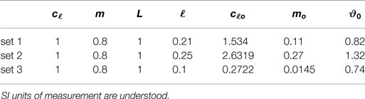
Table 1. Sets of parameters for selected triangular lattices with resonators whose frequency dispersion (see Figure 3) is Dirac-like at ω = π.
3. Localization and Edge Waves at the Dirac-Like Point
In this section, we investigate the wave forms, which correspond to the frequencies in the neighborhood of the Dirac-like point. In addition, we study the propagation of edge waves along the interfaces obtained by modifying the bulk homogeneous lattices. The periodic lattice’s dynamic response to point loads of different orientations is studied using the Finite Element Method (COMSOL Multiphysics). In the computations, we truncate the lattice retaining an N × N cluster of TLR cells, where N ≈ 50. In order to reduce spurious reflections from the boundaries of the computational window, the dynamic equations of the nodal points close to the sides of the grid include a damping term. The damping layer has width LD = 4 L and is non-uniform with spatial distribution , where σ = 1/L and η0 is a frequency-dependent factor and x = [0, LD] spans from the inner to the outer boundary of the damping frame. The harmonic responses shown in this section are triggered by a point force of frequency ω = π rad/s, linear polarization, and amplitude F = 0.1 N. We assume that the force is exerted on a triangular lattice node located at the center of the clusters. The lattice parameters considered here are listed in Table 1, where SI units of measurement and angles in unit of radiant are understood. These parameters have been chosen to reproduce a triple eigenvalue at Γ and frequency ω = π rad/s at the Dirac-like point (see Section 2.2).
The effective properties of the dispersion surfaces emanating from the Dirac-like point strongly influence the harmonic response of the structure. Special attention is given to the influence of the effective mass of the parabolic-in-k mode, and to the effective group velocities of the conical modes, on the localization patterns and on the amplitude and wavelength of the edge waves propagating along the interfaces obtained from the bulk TLRs.
3.1. Edge Waves along the Interface between Non-Homogeneously Tilted TLR
Figures 4A–C show the harmonic responses of a cluster with lattice parameters as in set 1 of Table 1. In these computations, three different linearly polarized forces have been used, each of which is oriented at 0, π/3, and π/6 with respect to the horizontal axis (see black arrows). In Figures 4A–C, we observe a localization pattern consistent with the flat band intersecting the Dirac cone at the triple eigenvalue. The symmetry axis of the localization pattern follows the polarization angle of the force. Figures 4D–F show the harmonic responses of a special cluster of resonators in which an inhomogeneity has been introduced via the tilting angle. The remaining parameters are listed in “set 1” of Table 1 and the harmonic force is the same as in Figures 4A–C. Above the thin black line, the resonators are tilted in the anticlockwise direction (ϑ0 = − 0.82), while below the line, a clockwise tilting (ϑ0 = 0.82) is implemented. This inhomogeneity introduces an interface that runs along the thin black line. It shall be pointed out that the dispersion surfaces of the lattice of resonators with clockwise and anticlockwise tilting are identical. In particular, the effective group velocities at the Dirac-like point are identical. Nevertheless, the harmonic response of the non-homogeneous cluster differs significantly from the corresponding responses of the homogeneously tilted cluster. In fact, we observe that a point force of frequency ω = π rad/s, corresponding to the Dirac-like point, triggers an edge wave traveling along the interface. The amplitude of the edge wave depends on the orientation of the harmonic point force, being larger for larger deflections from the horizontal direction (cf. Figures 4D–F). In each of the three panels, the elastic edge wave propagating along the interface has elliptic polarization whose principal axis is oriented at π/3 with respect to the interface. When the linear polarization angle of the source matches π/3 (see Figure 4F), the amplitude of the edge wave is greater than the other two cases for geometrical reasons.
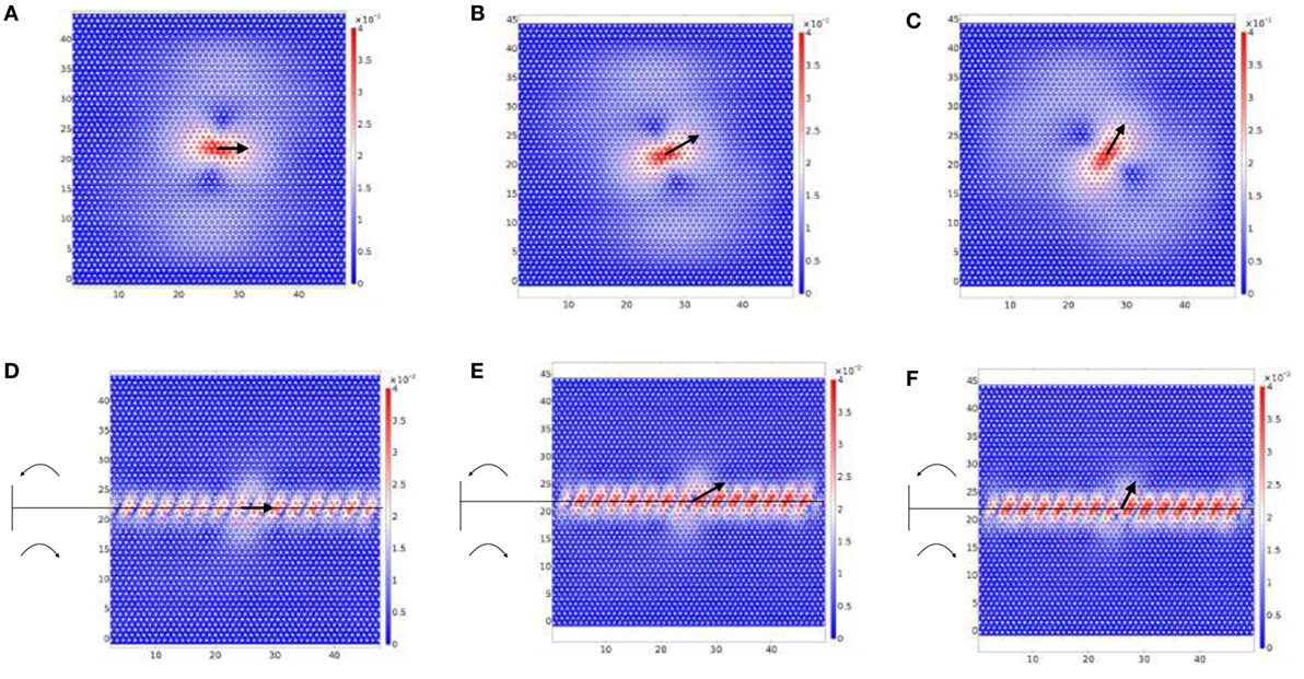
Figure 4. Panels (A–C) are the responses of a homogeneous TLR to a harmonic force of amplitude F = 0.1 N and frequency ω = π rad/s applied to a TL nodal point. The point loads (see black arrows) form an angle of 0, π/6, and π/3, respectively, with respect to the horizontal axis. Panels (D–F) are the responses of a non-homogeneous TLR to harmonic forces identical to those considered in panels (A–C), respectively. The thin horizontal line marks the interface between anticlockwise tilting (upper part, ϑ0 = − 0.82 rad) and clockwise tilting (lower part, ϑ0 = 0.82 rad). The lattice parameters used in all panels—the same as in Figure 3A—are given in the first row of Table 1.
In the same spirit as in Figure 4, Figure 5 shows the harmonic responses of clusters whose lattice parameters are listed in “set 2” (panels (A,B)) and “set 3” (panels (C,D)) of Table 1. The aim here is to illustrate how different dispersive properties near the Dirac-like point, already highlighted in Figure 3D, affect the harmonic responses of homogeneously tilted clusters (Figures 5A,C) and non-homogeneously tilted clusters (Figures 5B,D). The non-homogeneity considered here has the same meaning as in Figure 4. Figures 5A,C show localized patterns similar to that encountered in Figure 4A. Figures 5B,D show an edge wave traveling across the interface. We remark that the wavelength of the edge waves is larger for smaller effective group velocities at the Dirac-like point ω = π rad/s. This suggests that the dynamics of the edge waves is controlled by the effective group velocities at the Dirac-like point.
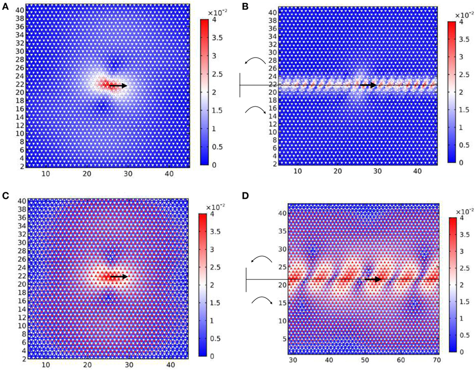
Figure 5. Panels (A,C) are the responses of a homogeneously tilted cluster of resonators to a harmonic horizontal force of frequency ω = π rad/s and amplitude F = 0.1 N. The lattice parameters are the same as represented in Figure 3D by the red dashed line and the blue dotted line, respectively. Panels (B,D) are the responses of a non-homogeneously tilted cluster of resonators to a harmonic horizontal force of frequency ω = π rad/s and amplitude F = 0.1 N. In panels (B,D), the tilting angle is oriented anticlockwise (clockwise) above (below) the thin horizontal line. The remaining lattice parameters, including the modulus of the tilting angle, are the same as in panels (A,C).
3.2. Edge Waves along a Line Defect in a Non-Homogeneously Tilted TLR
Figure 6 shows the modulus of the displacement field for a forced TLR containing a defect, which consists of a missing line of resonators, as shown in the magnified inset highlighted in yellow on the right of the figure. The lattice parameters used in this computation are listed in set 1 of Table 1 and the tilting angle is anticlockwise and clockwise, above and below the defect, respectively. The harmonic force is identical to the one used in Figure 4A and is exerted on a triangular lattice nodal point below the line defect (see blue arrow in the inset). We observe that the defect acts as a wave guide for an edge wave whose wavelength differs from the one in Figure 4B. We emphasize again that the wave-guiding behavior in Figure 6 differs significantly from the localization pattern in Figure 4A, the bulk homogeneous counterpart.
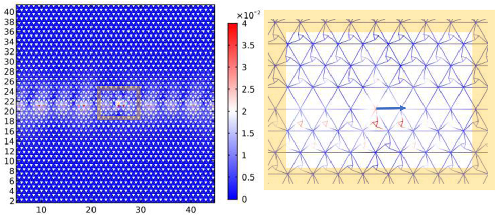
Figure 6. Response of a defective triangular lattice with resonators to a harmonic point force. The defect consists of a horizontal line along which resonators are removed, as highlighted in the yellow magnified inset on the right. The point force is represented in the right inset by the blue arrow and has amplitude F = 0.1 N and frequency ω = π rad/s. The parameters used in this computation are listed in the first row of Table 1 and the tilting angle is anticlockwise and clockwise, above and below the defect, respectively.
4. Wave Forms Around a Crack Surrounded by a Micro-Structured Coating
In this section, we study a special coating for one-dimensional cracks inside a TL. We consider a shear plane wave of angular frequency ω = π rad/s impinging on the crack. The coating is obtained by introducing resonators around the crack.
The physical parameters of the exterior triangular lattice in which the plane wave propagates can be chosen in order to guarantee an isotropic dynamic response. In this section, the maximum plane wave’s frequency is ω = π rad/s. The stiffness of the links cTL = 50 N/m, for the mass of the nodal points corresponding to mTL = m + 3mo = 1.43 kg (see set 1 in Table 1), guarantees an isotropic dynamic response. We observe that the aforementioned choice of the mass minimizes the spurious scattering effects associated with a contrast of inertia. Figure 7A shows a shear plane wave of frequency ω = π rad/s propagating through the isotropic triangular lattice. The wave is excited by applying a time-harmonic horizontal displacement to the nodal points of the lattice close to the horizontal line y = 45. In Figure 7B, a crack obtained by removing some links from the triangular lattice scatters the shear plane wave.
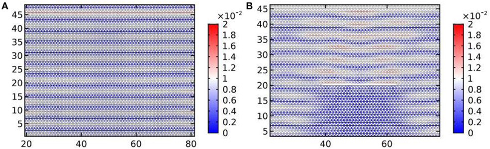
Figure 7. Panel (A) shows a shear plane wave of angular frequency ω = π rad/s traveling through a homogeneous triangular lattice. In panel (B), the same shear wave is scattered by a one-dimensional uncoated crack.
In this section, the lattice parameters of the structured coating are given in set 1 of Table 1. The corresponding dispersion surfaces are reported in Figure 3A. The different frequency regimes are discussed via the analysis of the scattered displacement fields: in section 4.1, we address the frequencies close to the Dirac-like point and in section 4.2 we focus on the band gap regime.
4.1. Dirac-Like Regime
In Figure 8, we compare the modulus of the displacement field resulting from the interaction of an elastic shear wave with a cluster of resonators (Figure 8A) and with a cluster of resonators containing a crack (Figure 8B). The source of the excitation is a plane wave of frequency ω = π rad/s, which corresponds to the Dirac-like point for the periodic TLR (see Figure 3). Figure 8A shows that scattering of elastic waves is highly anisotropic, the displacement field being concentrated on the right side of the cluster. It is worthwhile noting that if the resonators are rotated in the anticlockwise direction (ϑ0 = − 0.82), the displacement field is mirror-symmetric compared to the one in Figure 8A. The introduction of a crack within the cluster (Figure 8B) triggers the propagation of elastic waves around the crack itself. The displacement field and the corresponding stresses are still visibly concentrated around the right tip of the crack. This suggests that a coating of resonators in the Dirac-like regime is likely to lead to a left–right asymmetry in the propagation of the crack.
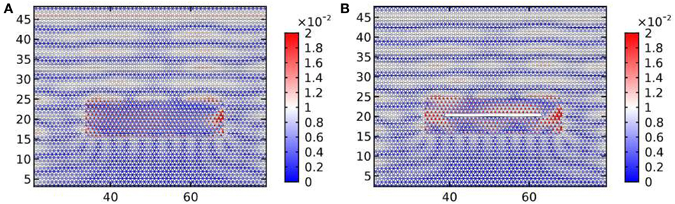
Figure 8. The harmonic responses to a shear plane wave of frequency ω = π rad/s corresponding to the Dirac-like point for the TLR. Panels (A,B) represent a cluster of resonators and a crack surrounded by a cluster of resonators, respectively. The parameters used to model the clusters are listed in set 1 of Table 1.
In Figure 9, long strips of resonators containing a crack interact with a shear plane wave impinging on the strip from above. Several arrangements for the resonators are considered. In Figure 9A,B, the resonators in the strip are homogeneously tilted in the clockwise (anticlockwise) direction. Similar to Figure 8A, this leads to an enhancement of the displacement field close to the tips of the cracks. Moreover, the results are mirror-symmetric about the vertical line passing through the center of the crack. This is consistent with what we observe in Figure 8B. In Figure 9C, the homogeneously tilted strip analyzed in Figure 9A has been replaced by a strip with an interface. The interface is represented by a line of missing resonators. The stiffness of the triangular lattice links that define the interface is assumed to be cTL = 50 N/m, as in the exterior triangular lattice. In Figure 9D, the strip is similar to the one in Figure 9C, but anticlockwise tilting above the line and clockwise tilting below the line are implemented. In Figures 9C,D, the displacement field is mirror-symmetric with respect to a vertical line passing through the crack.
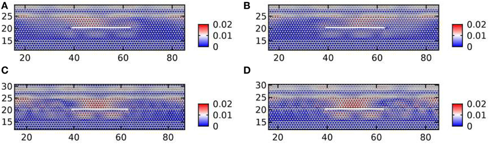
Figure 9. The harmonic responses to a shear plane wave of frequency ω = π rad/s corresponding to the Dirac point for the triangular lattice with resonators. In panels (A,B), we substitute the cluster of Figure 8B, which is finite in the horizontal direction, with an infinite strip. In panels (A,B), the tilting is clockwise and anticlockwise, respectively. The structure in panels (C,D) is obtained from panel (A) by removing a horizontal line of resonators along the extension of the crack. In panel (C), a homogeneous tilting is used; in panel (D), the resonators above the line are rotated anticlockwise and those below clockwise.
4.2. Band Gap Regime
In Figure 10, a shear plane wave coming from above impinges at normal incidence on a cluster of resonators (Figure 10A) and on clusters of resonators containing a crack (Figure 10B–D). The frequency of the excitation is ω = 2.4 rad/s corresponding to the band gap in Figure 3A. It is remarked that the coating is not penetrated by the incident wave. In particular, Figure 10B shows that the structured cluster acts as a protective layer for the crack, as one would expect from the analysis of the dispersion diagram for Bloch waves. In Figures 10C,D, we introduce a defect consisting of a missing line of resonators along the extension of the crack. In Figure 10C, the tilting angle is homogeneous, whereas in Figure 10D, the resonators are tilted in opposite directions above and below the line defect. The stiffness of the links of the line defects is the same as of the exterior triangular lattice. Figures 10C,D show a displacement enhancement at the perimeter of the cluster, however away from the crack tip. Figure 10E highlights an edge wave traveling along the boundary of the cluster.
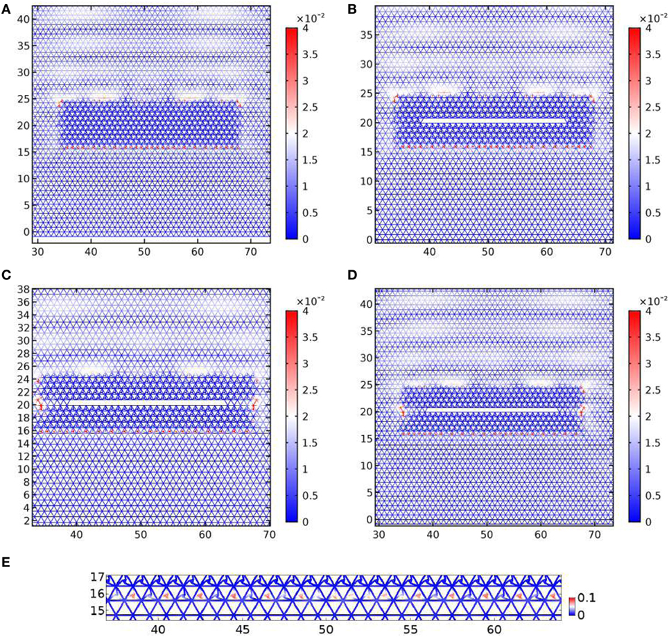
Figure 10. The harmonic response of a cluster of resonators to a shear plane wave of frequency ω = 2.4 rad/s inside the stop band for the TLR. Panels (A,B) are without and with a crack. Panels (C,D) include a line of resonators missing along the extension of the crack. In panel (C), the tilting angle is homogeneous, whereas in panel (D), the resonators are tilted through opposite angles. Panel (E) is a detail of the lower boundary of the cluster in panel (A) showing an edge wave. The lattice parameters are as in Figure 8.
In Figures 11A–C, the angular frequency ω = 2.1 rad/s of the plane wave corresponds to the lower edge of the band gap of Figure 3A. In Figures 11D–F, the frequency ω = 2.7 rad/s corresponds to the upper edge of the band gap. For the lower edge frequency, although the cluster is partially protective (see Figure 11B), the introduction of the one-dimensional defect increases the stress concentration around the crack (Figure 11C), compared to the uncoated configuration (Figure 11A). A similar effect is reported for the upper edge of the band gap in Figures 11E,F. In the vicinity of the band gap edges, the coating of resonators enhances the displacement field around the crack, increasing the chances for the crack to propagate.
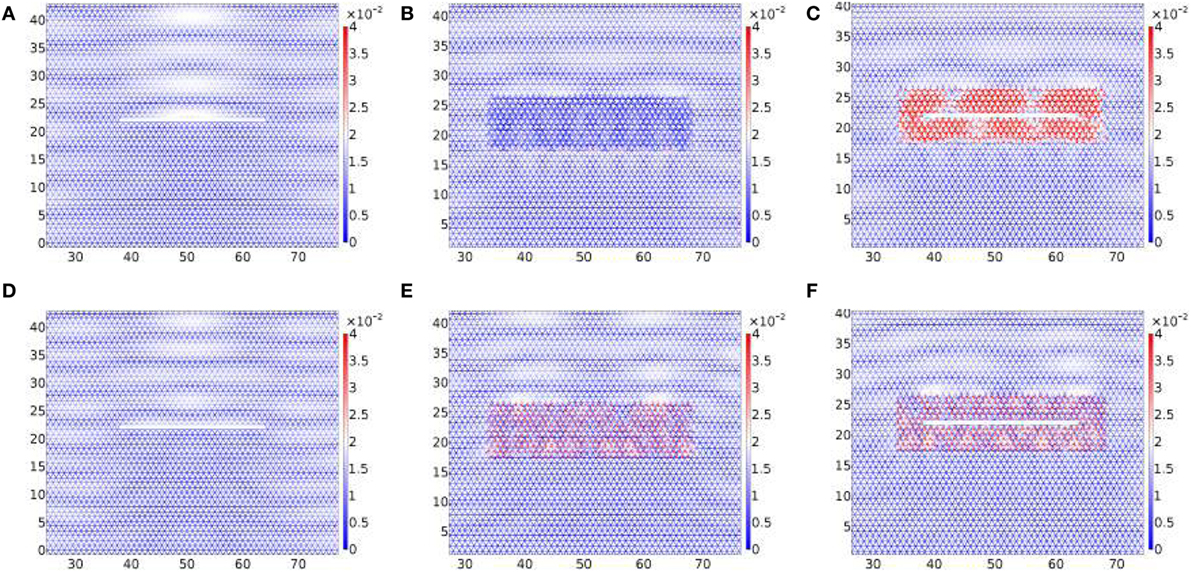
Figure 11. The harmonic response to a shear plane wave. Panels (A,D), (B,E), and (C,F) comprise a crack, a cluster of resonators, and a crack surrounded by a cluster of resonators, respectively. The angular frequency for panels (A–C) is ω = 2.1 rad/s corresponding to the lower edge of the band gap of Figure 3A. The shear wave’s angular frequency for panels (D–F) is ω = 2.7 rad/s corresponding to the upper edge of the band gap of Figure 3A.
5. Edge Crack Subjected to a Transient Thermal Load
The governing equations, loading configuration, and the fracture criterion are the same as in the earlier computations for the thermoelastic crack advancing through a homogeneous triangular lattice (Trevisan et al., 2016). Here, a geometrically chiral coating surrounding the crack is introduced into the model. An elastic wave is generated as a result of a rapid variation of the boundary temperature. The fracture criterion is based on a normalized threshold elongation ϵ = ΔL∕L. The crack advances when the ligament at the crack tip reaches the critical threshold elongation. The loading configuration is made of square pulses applied to the left edge of the computational domain. The period of the load is θ = 4τ, where τ = 16 s is the duration of a single pulse. The radian frequency of the pulse is ωs = 2π/θ = 0.0982 rad/s, where the subscript s stands for “striping”. The duration of the pulse is 60 θ. Figure 12 shows the Fourier spectrum of the temperature loading. We observe that the spectrum is dominated by spikes occurring at multiples of ωs. We limited the plot to , where the most pronounced spikes of the spectrum appear.
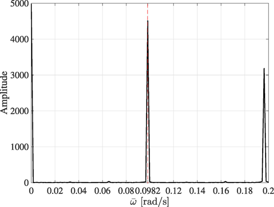
Figure 12. The Fast Fourier Transform of the input pulsating load has identified a countable number of spikes at different frequencies. Two spikes in the low frequency regime are shown here.
Tilted resonators are added as four layers (two above and two below the crack). The trusses that link the resonators to the TL’s nodal points are thermally insulating. The mass of the unit cell containing a resonator is not equal to the mass of the exterior triangular lattice nodal points. In Table 2, we list the thermoelastic parameters used in the transient non-linear simulations. The dispersion diagrams corresponding to the periodic lattices are represented in Figure 13. Figure 13A represents the dispersion surfaces for the triangular lattice outside the cracked strip. Figures 13B,C show the dispersion diagrams for two triangular lattices with resonators that differ from each other by the tilting angle (47° and 78°, respectively). The structured lattices are deliberately designed in such a way that ωs lies in the passband for Figure 13B and in the stop band for Figure 13C, as highlighted by the horizontal red lines.
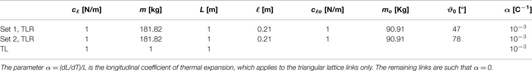
Table 2. Thermoelastic parameters for the ambient triangular lattice (third row) and for triangular lattices with resonators (first and second rows).
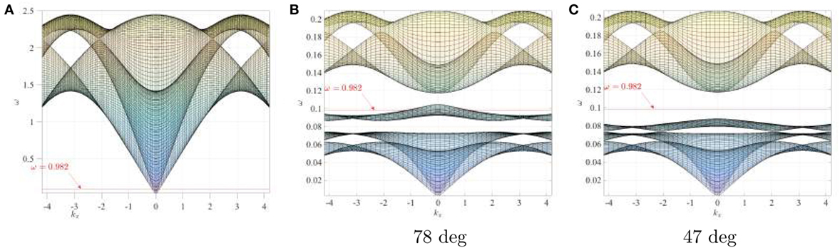
Figure 13. Dispersion surfaces for a TL (panel (A)) and for two TLRs (panels (B,C)). Panel (A) has been obtained using the parameters listed in the third row of Table 2. Panels (B,C) correspond to the parameters listed in the second and first rows of Table 2, respectively.
From the transient solution of the thermoelastic problem described above, we extracted the crack length Lc at several time intervals. The results are represented in Figure 14 for different normalized elongation thresholds ϵ. Figure 14A corresponds to the lower tilting angle and Figure 14B to the higher one. At the same elongation thresholds, the average crack speeds in Figure 14A are slightly higher than those in Figure 14B. We provide a qualitative interpretation of this phenomenon as follows. The thermal shocks trigger elastic waves whose amplitudes vs frequency at the left edge of the computational window differ from Figure 12 by a multiplicative constant. When ωs is in the passband, i.e., when ϑ0 = 78°, elastic waves can propagate along the strip of tilted resonators (see Figure 13), resulting in a reduction of strain concentration at the crack tip compared to the ϑ0 = 47° configuration. Equivalently, the strip of resonators acts as a structured waveguide that channels the energy away from the crack tip, as illustrated in Figure 15. On the contrary, when ϑ0 = 47°, the waveguide action is being suppressed, which leads to the field localization around the crack and hence the stronger advance of the fracture through the lattice.
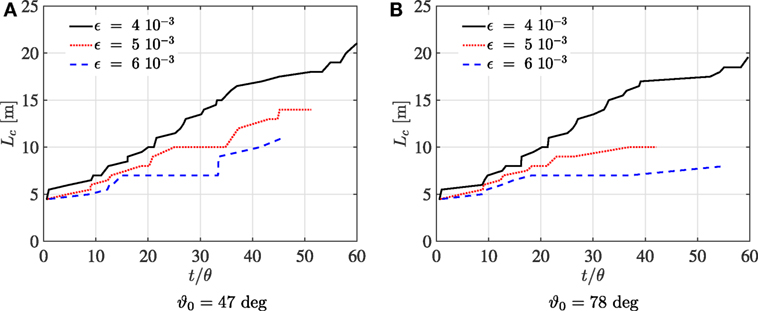
Figure 14. Crack length Lc as a function of time for two configurations corresponding to two tilting angles. The hosting triangular lattice and the parameters for the two lattices with resonators are reported in Table 2. (A) ϑ0 = 47°. (B) ϑ0 = 78°.
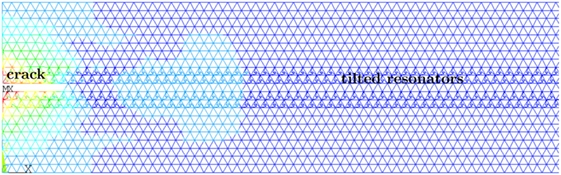
Figure 15. Instantaneous modulus of the displacement for the time step t/θ ≈ 10 in the transient simulation represented in Figure 14B for the elongation threshold (red dotted line). The crack tip “emits” elastic waves that propagate along the coating.
6. Concluding Remarks
We have identified several important applications of a novel geometrically chiral micro-structure in the design of advanced materials, used as filters/polarizers of elastic waves.
A transient advance of a crack, whose instantaneous snapshot is given in Figure 15, has been studied in a micro-structured layer where tilted resonators in the lattice are present. The analysis of the transient crack advance illustrated by Figures 14A,B is linked to the tunable dispersion properties of the lattices (see Figure 13) and to the guiding features of the structured coating around the crack, as shown in Figure 15.
The Dirac-like dynamic regime deserves a special mention. It has been achieved and studied here in relation to the wave-guiding and wave-defect interaction problems. Asymmetries in the scattered elastic field have been identified for waves at the Dirac-like frequency. This in turn empowers further studies in the context of asymmetric crack initiation mechanisms (see Figures 8 and 9).
Shielding of a defect from an incident elastic shear wave has been achieved in the regimes, which correspond to the complete band-gap of the triangular lattice with resonators. In addition to the usual low penetration of external waves within the protecting coating, we emphasize that edge waves occur around the perimeter of the coating in our model (see Figure 10). This is a “finger-print” of the lattice’s geometric chirality and cannot be achieved by the straightforward adjustment of the triangular lattice parameters, e.g., by introducing a contrast in the inertia or stiffness.
Author Contributions
DT obtained the analytical results relative to Section 2 and the FEM computations in Sections 3 and 4, generated the figures and drafted the text of the paper. AT performed the simulations of the crack advance (Section 5). NM and AM conceived the models here investigated, supervised the work, and contributed to the final version of the manuscript.
Conflict of Interest Statement
The authors declare that the research was conducted in the absence of any commercial or financial relationships that could be construed as a potential conflict of interest.
Funding
DT gratefully acknowledges the People Program (Marie Curie Actions) of the European Union’s Seventh Framework Program FP7/2007-2013/under REA grant agreement number PITN-GA-2013-606878. The paper was completed while DT was in a work secondment at Enginsoft (Italy), whose stimulating and welcoming environment is gratefully acknowledged. AM and NM acknowledge the financial support of the EPSRC through program grant EP/L024926/1. The paper was completed while AM was visiting the University of Trento; the support from the ERC Advanced Grant Instabilities and non-local multiscale modeling of materials FP7-PEOPLE-IDEAS-ERC-2013-AdG is gratefully acknowledged.
References
Bigoni, D., Guenneau, S., Movchan, A. B., and Brun, M. (2013). Elastic metamaterials with inertial locally resonant structures: application to lensing and localization. Phys. Rev. B 87:174303. doi: 10.1103/PhysRevB.87.174303
Brun, M., Jones, I. S., and Movchan, A. B. (2012). Vortex-type elastic structured media and dynamic shielding. Proc. R. Soc. Lond. A Math. Phys. Eng. Sci. 468, 3027–3046. doi:10.1098/rspa.2012.0165
Carta, G., Brun, M., Movchan, A., Movchan, N., and Jones, I. (2014). Dispersion equations in vortex-type monoatomic lattices. Int. J. Solids Struct. 51, 2213. doi:10.1016/j.ijsolstr.2014.02.026
Carta, G., Jones, I., Brun, M., Movchan, N., and Movchan, A. (2013). Crack propagation induced by thermal shocks in structured media. Int. J. Solids Struct. 50, 2725–2736. doi:10.1016/j.ijsolstr.2013.05.001
Carta, G., Jones, I. S., Movchan, N. V., Movchan, A. B., and Nieves, M. J. (2017). “Deflecting elastic prism” and unidirectional localisation for waves in chiral elastic systems. Sci. Rep. 7, 26. doi:10.1038/s41598-017-00054-6
Colquitt, D., Makwana, M., and Craster, R. (2015). High-frequency homogenisation for lattices. Q. J. Mech. Appl. Math. 68, 203–230. doi:10.1093/qjmam/hbv005
Colquitt, D., Nieves, M., Jones, I., Movchan, N., and Movchan, A. (2012). Trapping of a crack advancing through an elastic lattice. Int. J. Eng. Sci. 61, 129–141. doi:10.1016/j.ijengsci.2012.06.016
Craster, R., Kaplunov, J., and Pichugin, A. (2010). High-frequency homogenisation for periodic media. Proc. R. Soc. A 466, 2341–2362. doi:10.1098/rspa.2009.0612
Craster, R., Kaplunov, J., and Postnova, J. (2013). High-frequency asymptotics, homogenisation and localisation for lattices. Q. J. Mech. Appl. Math. 63, 497–519. doi:10.1093/qjmam/hbq015
Haslinger, S. G., Movchan, N. V., Movchan, A. B., Jones, I. S., and Craster, R. V. (2017). Controlling flexural waves in semi-infinite platonic crystals with resonator-type scatterers. Q. J. Mech. Appl. Math. hbx005. doi:10.1093/qjmam/hbx005
Joseph, L., and Craster, R. (2013). Asymptotics for Rayleigh-Bloch waves along lattice line defects. Multiscale Model. Simul. 1, 871–889. doi:10.1137/120872401
Kozlov, V., Maz’ya, V. G., and Movchan, A. B. (1999). Asymptotic Analysis of Fields in Multi-Structures. Oxford University Press.
Li, Y., and Mei, J. (2015). Double Dirac cones in two-dimensional dielectric photonic crystals. Opt. Express 23, 12089–12099. doi:10.1364/OE.23.012089
Liu, X., Huang, G., and Hu, G. (2011). Wave propagation characterisation and design of two-dimensional elastic chiral metacomposite. J. Sound Vib. 330, 2536–2553. doi:10.1016/j.jsv.2010.12.014
Liu, X., Huang, G., and Hu, G. (2012). Chiral effect in plane isotropic micropolar elasticity and its application to chiral lattices. J. Mech. Phys. Solids 60, 1907–1921. doi:10.1016/j.jmps.2012.06.008
Mei, J., Wu, Y., Chan, C., and Zhang, Z.-Q. (2012). First-principles study of Dirac and Dirac-like cones in phononic and photonic crystals. Phys. Rev. B 86, 035141. doi:10.1103/PhysRevB.86.035141
Movchan, A., and Slepyan, L. (2014). Resonant waves in elastic structured media: dynamic homogenisation versus Green’s functions. Int. J. Solids Struct. 51, 2254–2260. doi:10.1016/j.ijsolstr.2014.03.015
Slepyan, L. I. (2002). Models and Phenomena in Fracture Mechanics. Berlin, Heidelberg, New York: Springer.
Smith, M., McPhedran, R., and Meylan, M. (2014). Double Dirac cones at k = 0 in pinned platonic crystals. Waves Random Complex Media 24, 35–54. doi:10.1080/17455030.2013.862351
Spadoni, A., and Ruzzene, M. (2012). Elasto-static micropolar behaviour of a chiral auxetic lattice. J. Mech. Phys. Solids 60, 156–171. doi:10.1016/j.jmps.2011.09.012
Spadoni, A., Ruzzene, M., Gonnella, S., and Scarpa, F. (2009). Phononic properties of hexagonal chiral lattices. Wave Motion 46, 435–450. doi:10.1016/j.wavemoti.2009.04.002
Süsstrunk, R., and Huber, S. (2015). Observation of phononic helical edge states in a mechanical topological insulator. Science 349, 47–50. doi:10.1126/science.aab0239
Tallarico, D., Movchan, N., Movchan, A., and Colquitt, D. (2017). Tilted resonators in a triangular elastic lattice: chirality, Bloch waves and negative refraction. J. Mech. Phys. Solids 103, 236–256. doi:10.1016/j.jmps.2017.03.007
Trevisan, A., Borzi, G., Movchan, N., Movchan, A., and Brun, M. (2016). Thermal shock driven fracture in a structured solid: dynamic crack growth and nucleation. Int. J. Fract. 202, 167–177. doi:10.1007/s10704-016-0118-6
Keywords: elasticity, lattices, metamaterials, Dirac-like cones, edge waves
Citation: Tallarico D, Trevisan A, Movchan NV and Movchan AB (2017) Edge Waves and Localization in Lattices Containing Tilted Resonators. Front. Mater. 4:16. doi: 10.3389/fmats.2017.00016
Received: 31 March 2017; Accepted: 30 May 2017;
Published: 30 June 2017
Edited by:
Bruno Morvan, University of Le Havre, FranceReviewed by:
Gennady Mishuris, Aberystwyth University, United KingdomMichael Nieves, Liverpool John Moores University, United Kingdom
Michele Brun, Università degli studi di Cagliari, Italy
Copyright: © 2017 Tallarico, Trevisan, Movchan and Movchan. This is an open-access article distributed under the terms of the Creative Commons Attribution License (CC BY). The use, distribution or reproduction in other forums is permitted, provided the original author(s) or licensor are credited and that the original publication in this journal is cited, in accordance with accepted academic practice. No use, distribution or reproduction is permitted which does not comply with these terms.
*Correspondence: Domenico Tallarico, domenico.tallarico@liverpool.ac.uk