Full Scale Reinforced Concrete Beam-Column Joints Strengthened with Steel Reinforced Polymer Systems
 Alessandro De Vita
 Annalisa Napoli
 Roberto Realfonzo
- Department of Civil Engineering, University of Salerno, Fisciano, Italy
This paper presents the results of an experimental campaign performed at the Laboratory of Materials and Structural Testing of the University of Salerno (Italy) in order to investigate the seismic performance of reinforced concrete (RC) beam-column joints strengthened with steel reinforced polymer (SRP) systems. With the aim to represent typical façade frames’ beam-column subassemblies found in existing RC buildings, specimens were provided with two short beam stubs orthogonal to the main beam and were designed with inadequate seismic details. Five members were strengthened by using two different SRP layouts while the remaining ones were used as benchmarks. Once damaged, two specimens were also repaired, retrofitted with SRP, and subjected to cyclic test again. The results of cyclic tests performed on SRP strengthened joints are examined through a comparison with the outcomes of the previous experimental program including companion specimens not provided with transverse beam stubs and strengthened by carbon fiber-reinforced polymer (CFRP) systems. In particular, both qualitative and quantitative considerations about the influence of the confining effect provided by the secondary beams on the joint response, the suitability of all the adopted strengthening solutions (SRP/CFRP systems), the performances and the failure modes experienced in the several cases studied are provided.
Introduction
The severe damage exhibited by reinforced concrete (RC) framed buildings under earthquakes has frequently proven the high vulnerability of existing structures toward seismic actions, mainly due to an unsatisfactory behavior of beam-column joints. The condition is mostly found in the case of corner joints or those belonging to façade frames, only partially confined for the absence of beams on the four joint faces; such members, often characterized by absence of stirrups, non-optimal arrangement of transverse and/or longitudinal rebars, or manufactured with low quality concrete, show a progressive deterioration of both strength and stiffness under seismic excitation.
Several repair and strengthening solutions for beam-column joints have been investigated in the literature; a wide overview can be found in Engindeniz et al. (2005). Among them, the systems employing glass (G) or carbon (C) fiber-reinforced polymer (FRP) materials have met an increasingly widespread consensus in the civil engineering field as witnessed by the growing number of experimental papers published on this topic; a state-of the-art review can be found in Bousselham (2010). It is first highlighted the experimental study by El-Amoury and Ghobarah (2002); the Authors used a composite material system made of a bidirectional glass fiber sheet—applied via wet layup using epoxy resin—with the twofold objective of: (a) increasing the shear strength of the joint panel, and (b) improving the bond between the beam’s longitudinal steel rebars and the surrounding concrete.
In a further study, the same Authors presented the experimental results of tests performed on substandard RC joints strengthened by using GFRP or CFRP materials in combination with steel members (Ghobarah and El-Amoury, 2005).
The seismic retrofitting of non-ductile beam-column subassemblage using both FRP wrapping and steel plate jacketing was also examined by Sasmal et al. (2011); the results showed that the specimen retrofitted with the proposed technique not only regained its original strength and stiffness but also overcame the deficiencies of non-ductile detailing.
The use of a RC jacket and high-strength fiber jacket for cases of post-earthquake and pre-earthquake retrofitting of exterior beam-column joints was experimentally investigated by Tsonos (2008); the performed tests showed that the RC jacket seem to be more effective in a post-earthquake retrofitting of specimens than the high-strength fiber jacket, whereas, in the case of pre-earthquake strengthening, both systems seem to be equally effective.
An extensive experimental campaign was performed by Antonopoulos and Triantafillou (2003); they tested 18 RC joints representative of existing building’s structural components designed by using out-of-date codes, i.e., without considering the construction details recommended in seismic areas. The following aspects were investigated: presence of longitudinal and transverse steel reinforcement in the joint panel; axial load level in the column; amount, geometry, and type of FRP reinforcement (sheets or laminates) in the beam and column members; employed FRP system (GFRP or CFRP); presence of a transverse beam contributing to the joint confinement.
Additionally, the study published by Al-Salloum et al. (2011) is mentioned, where the performance of using textile-reinforced mortar (TRM) to strengthen seismically deficient RC beam-column joints was compared with that of FRP; test results showed that, with the use of a sufficient number of layers, the TRM system can effectively increase both the shear strength and deformation capacity similarly to the case of GFRP and CFRP systems.
The results of an interesting experimental investigation were published by Del Vecchio et al. (2014) on full scale RC corner joints strengthened with different CFRP layouts employing both uniaxial and quadriaxial sheets; one of the proposed solutions is currently reported in the guidelines DPC/Reluis (2011) developed in Italy in order to support practitioners in the design process of FRP strengthening in beam-column joints and to establish suitable field installation procedures.
An experimental study was also performed by Realfonzo et al. (2014) with the aim to investigate the behavior of shear-deficient RC beam-columns joints strengthened with CFRP systems, sometimes coupled with steel profiles and/or steel rods to further improve the behavior under combined axial load-bending moments actions.
Furthermore, a few analytical procedures for estimating the performance of existing RC beam-column joints before and after being retrofitted with FRPs were proposed in the literature (Akguzel and Pampanin, 2012; Del Vecchio et al., 2014).
Besides the FRP systems, a new generation of composites made of steel tapes in lieu of carbon or glass fiber sheets has lately emerged in the civil engineering field thanks to excellent mechanical properties other than the very competitive costs. The steel tape, whose first applications in Italy already date back to L’Aquila earthquake in 2009, consists of high tensile strength steel (HTSS) cords made by twisting steel wires within a micro-fine brass or galvanized coating; it can be in situ applied via wet lay-up by using epoxy resin or inorganic matrix, thus obtaining strengthening systems known with the acronym of SRP (“steel reinforced polymer”) and SRG (“Steel Reinforced Grout”), respectively.
The tape is manufactured in different densities (generally denoted as low, medium or high) based on the number of cords per unit width.
Despite the attractive potentialities, so far the scientific papers dealing with the use of steel composites for the strengthening of RC structural members are rather limited, as well as specific guidelines have not been published yet. Only recently there has been a greater interest by the scientific community in deeper understanding the behavior of SRP/SRG systems as witnessed by the high number of papers published since 2014. Lately, an updated state-of-the-art review of the experimental research performed on SRP systems only has also been published by De Santis et al. (2016). However, by focusing on the strengthening of RC beam-column joints, the literature is even more poor when compared with the information available for FRP systems. Among the few published papers, the experimental study by Izi et al. (2008) is mentioned, but performed on four 1/2-scale two-dimensional exterior joints strengthened with SRPs. Although the tested specimens did not faithfully represent the existing beam-columns subassemblies due to the absence of one beam (in the case of corner joints) or two beams (in the case of façade frames) in the transverse directions, test results clearly showed the SRP effectiveness in increasing the ductility and the strength of a beam-column joint with insufficient (or no) shear reinforcement.
With the aim to increase the current knowledge on this topic, an experimental program is still ongoing at the University of Salerno (Italy) on large scale RC beam-column joints strengthened with SRP and SRG systems. Specimens were designed to be representative of façade frames’ beam-column subassemblies, which are frequently found in existing RC buildings, i.e., characterized by inadequate seismic details and made of medium concrete compressive strength. In order to simulate the presence of transverse beams, two small concrete stubs orthogonal to the main beam were considered; the geometry and longitudinal/transverse steel reinforcement of both column and main beam are the same already adopted for some members included in the previous experimental program (Realfonzo et al., 2014), whose main details are reported in this paper.
The present paper focuses on the cyclic tests performed so far on beam-column joints strengthened with SRP only, and the main results are examined herein through a comparison with the outcomes of the previous experimental study on counterparts not provided with secondary beams and strengthened with CFRP systems (Realfonzo et al., 2014). In particular, considerations about the confining effect provided by the addition of the secondary beams, the suitability of all the adopted strengthening solutions (SRP/CFRP systems), the performances obtained in the several studied cases and the experienced failure modes are provided.
Experimental Program
The complete experimental program includes fifteen exterior RC beam-column joints subjected to reversed cyclic force applied to the main beam by keeping the column under a constant axial load. The specimens considered in this paper are seven, of which five were strengthened with SRP systems while the remaining ones were used as benchmarks (unstrengthened members); once damaged, two specimens were also re-tested after being repaired and retrofitted with SRP.
As mentioned earlier, the paper also includes some details on similar four specimens included in the previous experimental campaign, of which three were strengthened with CFRP systems and one was used as control member (Realfonzo et al., 2014); also in this case, one of the four specimens, once damaged, was re-tested after being repaired, and retrofitted with CFRP.
The following sections report a detailed description about RC specimens, strengthening layouts, repair and retrofitting techniques, test setup, and instrumentation.
RC Specimens
Figure 1A shows the geometry and the longitudinal/transverse steel reinforcement of test specimens which were designed to simulate, in a simplified manner, beam-column joints belonging to façade frames of existing buildings. They were made out of 2,000 mm long columns with 300 mm × 300 mm section, and 1,700 mm long beams with 300 mm × 400 mm section (labeled main beams in Figure 1). As shown in section “D-D,” the presence of secondary beams, providing a confining action to the joint, was simulated by 300 mm long members with 300 mm × 400 mm section. To this purpose, it is highlighted that the designed specimens (namely, “3D” joints), which according to the Italian Building Code (Decreto Ministeriale 14 gennaio, 2008) are classified as unconfined joints, cannot be truly representative of a beam-column joint since in the performed cyclic tests the shear and bending moment actions were not applied to the secondary beams due to technical limitations of the available testing equipment.
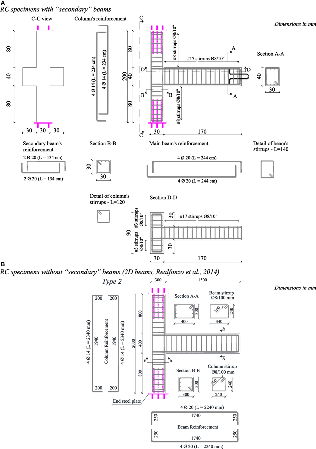
Figure 1. Geometry and steel reinforcement configuration for reinforced concrete specimens with (A) and without (B) “secondary” beams.
Columns were longitudinally reinforced by using (4 + 4) deformed steel rebars with 14 mm diameter (∅), whereas the main beams with (4 + 4) ∅20 rebars; in both members, the transverse reinforcement consisted of 8 mm diameter steel stirrups, 100 mm spaced. Finally, the secondary beams were reinforced with (2 + 2) ∅20 rebars crossing the joint zone.
Tensile tests were performed on small samples to characterize the yield (fsy) and the ultimate strength (fsu) of the transverse and longitudinal steel rebars; from these tests the following average values were found: fsy = 483 MPa and fsu = 615 MPa for 8 mm diameter; fsy = 497 MPa and fsu = 623 MPa for 14 mm diameter, and fsy = 495 MPa and fsu = 618 MPa for 20 mm diameter. Figures 2A,B show the typical experimental stress-strain responses found from these tests.
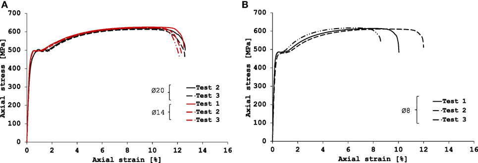
Figure 2. Typical stress-strain curves of the used longitudinal (A) and transverse (B) steel reinforcement.
With the aim of simulating the behavior of typical joints found in existing buildings, no steel stirrups were arranged in the joint panel; also, test specimens were manufactured with medium-low performance concrete, i.e., by using a concrete mix characterized by a target cylindrical compression strength of about 16 MPa. Then, the effective main value of the cylindrical compressive strength of concrete (fcm) for each specimen was obtained from compression tests performed on: (a) cubic 150-mm side samples taken during the casting of each beam-column joint, and (b) concrete core samples (diameter: 94 mm; height: 160–200 mm) extracted from the same joints after the cyclic test. From these tests, the average value of concrete cylindrical compressive strength at 28 days curing was found to be 20–21 MPa for all specimens.
As mentioned earlier, the geometry and steel reinforcement configuration of both column and main beam are the same already considered in the previous experimental program (Realfonzo et al., 2014) for the specimens “Type 2” (shown in Figure 1B). It is worth mentioning that in the “as-built” (unstrengthened) configuration, the design of these specimens which did not account for the presence of secondary beams (namely, “2D joints”), had been performed in order to have the column weaker than the beam but always stronger than the joint panel (the weakest member). In the “strengthened” configuration, instead, the FRP upgrading was designed with the aim to improve the performance of the joint panel by mainly avoiding the premature failure of the column during the cyclic test. More details on the specimens design can be found in Realfonzo et al. (2014).
SRP Materials and Strengthening Layouts
The SRP systems investigated in this study entail unidirectional textiles of HTSS cords. Each cord has a cross section area (Acord) of 0.538 mm2 and is made out of five wires with 0.11 mm2 area, three straight and two twisted around them at a short lay length (“3 × 2” cord). Wires are galvanized (coated with zinc) to provide protection against rusting and are installed on a supporting glass mesh to ease storage and installation (Hardwire LLC, 2016).1
Based on the number of cords distributed in the tape width, different densities (ρ) of the reinforcement material are commercially available, labeled by the supplier “GeoSteel G600,” “GeoSteel G2000,” and “GeoSteel G3300” in increasing order of the density (Kerakoll, 2016)2; it is noted that the number characterizing each label identifies, approximately, the weight of each tape expressed in g/m2.
For the specific case, “GeoSteel G2000” textile was used, indicated in the following with the acronym “MD” (i.e., medium density), whose main information about geometry and mechanical properties is reported in Table 1. In particular: the symbols ρ, s, and γ denote density, cord spacing and surface mass density of the textile, respectively; tf (= Acord ⋅ ρ) indicates the equivalent design thickness, whereas the last three columns provide the average values of the tensile strength (fs,u), the Young’s modulus (Es), and the strain corresponding to the peak stress (εs,u).
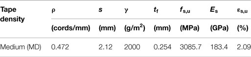
Table 1. Properties of medium density dry steel tapes.
The mechanical properties reported in Table 1, obtained from direct tensile tests performed on dry steel textiles, are discussed in a recent paper (Napoli et al., 2016).
The impregnating matrix used in the SRP strengthening system is a thixotropic epoxy mineral adhesive characterized by very low volatile organic compound emissions, with 46% natural mineral content; the main mechanical properties of this matrix can be found in technical sheets provided by the manufacturer (Kerakoll, 2016; see footnote 2).
Figure 3 shows the two SRP strengthening layouts considered in the experimental study which mainly differ for the arrangement of steel tapes on the joint panel, named “cross” (i.e., “+” scheme) or “diagonal” (i.e., “x” scheme).
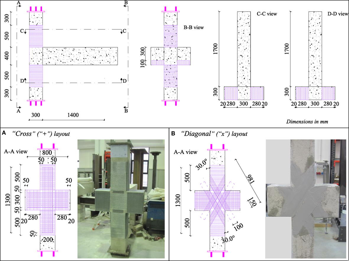
Figure 3. SRP strengthening schemes: cross (A) and diagonal (B) layout.
Both configurations also include the SRP confinement of the column in the portion located about 500 mm above and below the joint panel; such reinforcement was obtained by applying only one layer of MD steel tape.
In the “+” upgrading of the joint panel (Figure 3A), a 1,300 mm long and 200 mm wide SRP strip was applied to the column and restrained by the external SRP wrapping, while another sheet was applied to the two secondary beams and restrained by two U-shape strips simulating the presence of a beams’ shear strengthening. It is worth highlighting that the “cross” pattern was also considered for retrofitting the above mentioned two specimens that, after being tested and damaged, were repaired by using a thixotropic mineral mortar, retrofitted with SRP and subjected to cyclic test again.
In the “x” layout (Figure 3B), the joint panel was strengthened by two couples of diagonal SRP strips, each 100 mm wide, restrained by both the SRP wrapping of the column and the two U-shape strips on the beams.
CFRP Materials and Strengthening Layouts
The FRP systems investigated in the previous experimental campaign entailed unidirectional carbon fiber sheets, each 0.22 mm thick and characterized by an elastic modulus of 390 GPa, a tensile strength of 3000 MPa and an ultimate strain equal to 0.80%. The impregnating matrix consisted of a thixotropic, two part adhesive, characterized by an elastic modulus equal to 9.6 and 11.2 GPa in compression and tension, respectively; additional information on the mechanical properties of the used adhesive can be found in the technical sheets provided by the manufacturer (Sikadur, 2015).
Figure 4 shows the three CFRP upgrading schemes considered for the “2D” specimens which include the strengthening of both columns and joint panels. It is worth highlighting that such strengthening techniques, despite slight drawbacks related to the not ease and speed of installation, are currently employed by the Italian building company which technically and financially supported the experimental campaign.
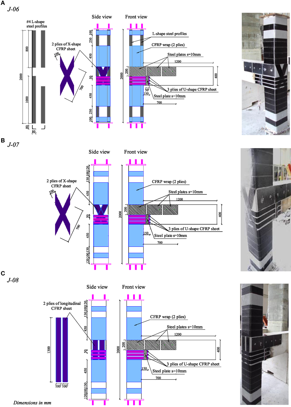
Figure 4. Carbon fiber reinforced polymer (CFRP) strengthening schemes: specimens J-06 (A), J-07 (B), and J-08 (C).
In order to simulate, in a simplified manner, the presence of a RC floor slab/beam which partially confines the exterior joint on the sides perpendicularly to the beam shown in the drawing of Figure 4 (issue addressed in the “3D” joints with the addition of the secondary beams), the three strengthening layouts included the arrangement of separated steel plates (three on each side), which were 10 mm thick, 200 mm wide, and about 300 mm long. The choice of using three smaller plates per side instead of a greater one allowed for minimizing any possible influence of the steel elements to the flexural response of the specimens.
As already highlighted for the “3D” specimens, the simulation of slabs/beams with steel plates of course do not carefully reflect the real behavior of the joint in an existing structure since the actions transferred to the joint by these concrete members were not taken into account.
In the strengthening scheme considered for the joint “J-06” (Figure 4A), the column upgrading is similar to that already considered by the authors in previous experimental investigations (Realfonzo and Napoli, 2009, 2012; Napoli and Realfonzo, 2015); it entailed four longitudinal cold bent steel profiles placed along the member corners before applying the external continuous wrapping made of two CFRP layers. The profiles were always glued to the concrete substrate by means of an epoxy adhesive and consisted of 80 mm × 80 mm × 6 mm equal leg angles made of structural steel S235. These were continuous on the exterior face of the joint and discontinuous on the interior one, thus providing the joint panel with a better confinement.
In the strengthening schemes considered for the joints “J-07” and “J-08” (Figures 4B,C, respectively), instead, the CFRP confinement of the columns was not coupled with the arrangement of steel profiles.
In the case of the specimens “J-06” and “J-07” (Figures 4A,B, respectively), the upgrading of the joint panel was characterized by the use of two CFRP sheets, each 100 mm wide, which were arranged on the outer face of the joint in a “x” shape and before applying the external wrapping of the column. The application was then completed by employing three U-shape CFRP-layers, 50 mm wide, which were anchored on the beam for a length of about 150 mm. In order to better exploit the tensile strength of the fibers by avoiding a premature FRP debonding during the tests, a mechanical anchorage was located on the beam in the portion close to the column-beam interface (i.e., where the FRP debonding should develop first due to the opening of the flexural cracks).
In the case of the specimen “J-08,” the strengthening of the joint panel was very similar to that of the counterparts J-06 and J-07 except for replacing the “x” configuration of the two CFRP sheets with the “vertical” one, as shown in Figure 4C.
Finally, it has to be highlighted that the scheme considered for the specimen “J-06” was also considered for retrofitting the above mentioned one specimen that, after being tested and damaged, was repaired by using a commercial mortar, retrofitted with CFRP and subjected to cyclic test again.
Test Setup
Figure 5 shows the setup adopted for subjecting the beam-column joints to reversed cyclic forces applied at the main beam by keeping the column under a constant axial load; it is very similar to that used in the previous tests (Realfonzo et al., 2014).
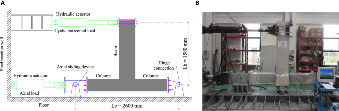
Figure 5. Test setup: schematic (A), and photo taken in the laboratory (B).
The column was mounted horizontally and restrained to both ends by assembling steel elements according to a roller-hinged scheme. It was pre-loaded in compression before applying the horizontal force by a 1,000 kN MTS hydraulic actuator fixed to a reaction steel frame. The axial load N was about 295 kN which corresponds to a normalized value of the compression load “ν” of about 0.16, with ν given by:
where Ag is the column cross-section and fcm is the average value of concrete cylinder compressive strength of each tested specimen.
The horizontal force was cyclically applied in displacement control at the main beam through a 250 kN MTS hydraulic actuator, mounted at 1,430 mm from the beam base and fixed to a reaction steel frame. An increment of the imposed horizontal displacement every three cycles was considered in order to evaluate the strength and stiffness degradation at repeated lateral load reversals. The increment of the displacement amplitude was given as fraction of the estimated beam yield displacement, Δy (≈14 mm); two different displacement rates were considered during the tests: 0.2 mm/s before the achievement of Δy and 1 mm/s after Δy.
All tests were stopped well beyond predetermined conventional collapses coinciding with the achievement of 15 and 25% strength decays estimated on the monotonic envelopes of the lateral force-displacement cyclic curves.
During tests, specimens were accurately instrumented in order to monitor strains, displacements, joint rotations, and crack widths as documented in Realfonzo et al. (2014).
Experimental Results and Discussion
Table 2 summarizes the main data and results of the considered tests, of which the first set of nine tests refers to specimens strengthened with SRP systems whereas the second one (five tests) to specimens strengthened with CFRP systems. In particular, within the first set, two tests were performed on unstrengthened members (test “JK1” and “JK11”) and five on specimens strengthened with SRP systems (test “JK3,” “JK4,” “JK7,” “JK8,” and “JK9”). The strengthening layouts are those shown in Figure 3, i.e., the “cross” (tests “JK3,” “JK7,”and “JK9”) and the “diagonal” (test “JK4” and “JK8”) one. The remaining two tests (tests “JK9r”and “JK11r”) were performed on the specimens “JK9”and “JK11” after repairing and SRP retrofitting; in these cases, the “cross” layout was always considered for the joint retrofitting.
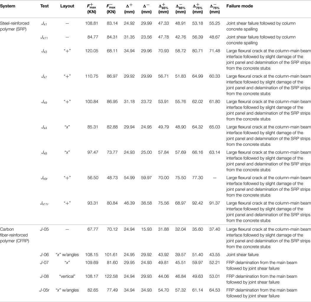
Table 2. Test results.
Within the second set, one test was performed on the control member (test “J-05”) and three on counterparts strengthened with CFRP systems according to the “vertical” (tests “J-08”) and the “diagonal” (tests “J-06” and “J-07”) layouts shown in Figure 4. The fifth test (tests “J-05r”) refers to the specimen J-05 that, after being damaged, was repaired, retrofitted by CFRP system (by considering the same layout of the specimens “J-06”) and subjected to cyclic test again.
In addition to test labels and indications on the strengthening layout, the following information is reported in Table 2:
✓ peak lateral forces applied to the beam in the two directions of loading ( and ) and corresponding displacements (Δ+ and Δ−);
✓ beam displacements exhibited at a 15% strength decay ( and ), i.e., at the achievement of 85% and 85% .
✓ beam displacements measured at 25% strength decay ( and ), i.e., at the achievement of 75% and 75% ;
✓ the main damage and failure modes observed during the tests.
The following sections better describe the obtained results in terms of crack pattern and failure mode experienced by specimens, strength and deformation capacity, energy, and stiffness degradation. Comparisons between the “2D”-FRP strengthened joints and the “3D”-SRP strengthened ones are also reported.
However, in regard to the set of SRP strengthened specimens, it is highlighted that the tests “JK1” and “JK3” are not exhaustively included in the discussion of the experimental results reported in §3.2 since the cyclic responses obtained in these two cases will deserve a better investigation. Indeed, as observed in Table 2, the unstrengthened joint “JK1” exhibited an unexpected so much good behavior with respect to the companion member “JK11”; the other specimen, instead, showed a significantly dissymmetric cyclic response in the two directions of loading which was not found to be so relevant from tests performed on companion members “JK7” and “JK9.”
Crack Pattern and Failure Mode
Figure 6 shows the comparison between the crack pattern and failure mode experienced by the unstrengthened specimen “J-05” and those of the counterparts “JK1” and “JK11,” thus showing the influence of the confinement effect provided by the secondary beams on the type of observed damage.
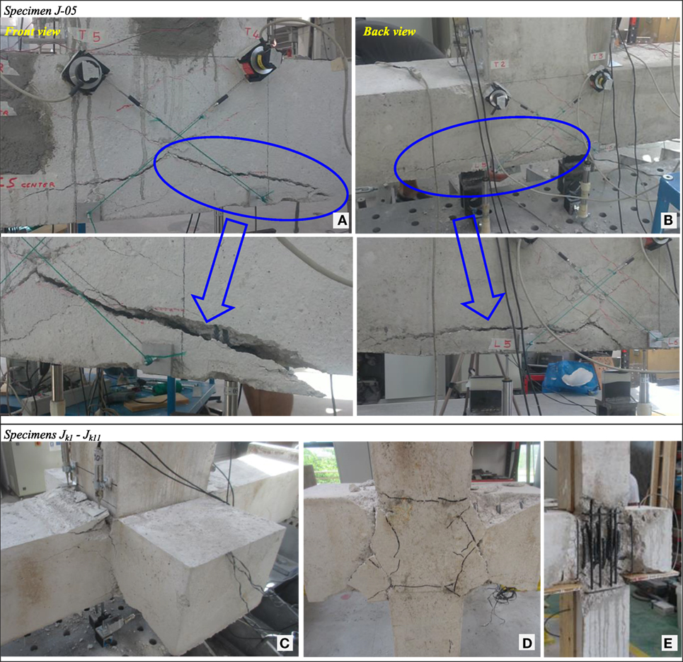
Figure 6. Crack pattern and failure for control specimens: J-05 (A,B); Jk1 and Jk11 (C–E).
In particular, Figures 6A,B depict the crack pattern of the unconfined joint “J-05” (Realfonzo et al., 2014). The shear cracks on the joint panel are clearly noted, as well as the removal of a significant portion of concrete on the outer side, caused by the push-in/pull-out action of the beam’s longitudinal steel rebars. Additionally, even though non-visible in the Figure, slight signs of column’s concrete crushing have been observed on the inner side, i.e., where the beam is located, whereas such beam did not show any evidence of damage.
Figures 6C–E show the damage experienced by the control members “Jk1” and “Jk11,” respectively. In this case, the introduction of the secondary beams had a non-negligible influence on the failure mode observed. Indeed, even though the joint panel experienced a severe damage (with incipient detachment of concrete portions on the secondary beams), this was lower than that shown by the counterpart “J-05.” Conversely, concrete spalling from the column member in the portion close to the main beam-column interface was observed mainly for the specimen Jk1 (Figure 6C). Figure 6D allows for better observing the joint crack pattern shown by the control specimens provided with secondary beams; by removing the outer portion of the concrete layer (see Figure 6E), signs of damage in the inner concrete core were noted.
Figures 7 and 8 show the scenario of damage experienced by specimens strengthened with CFRP systems and SRP systems, respectively.
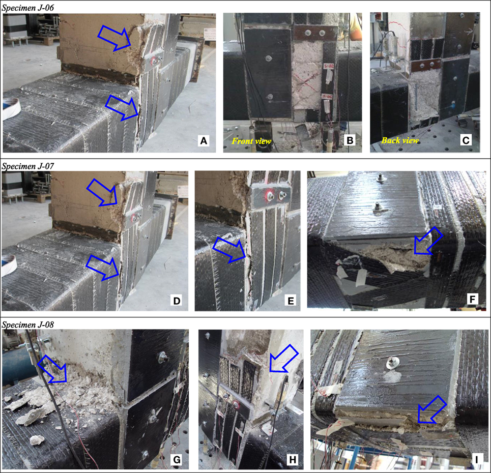
Figure 7. Crack pattern and failure for CFRP strengthened specimens: J-06 (A–C); J-07 (D–F); J-08 (G–I).
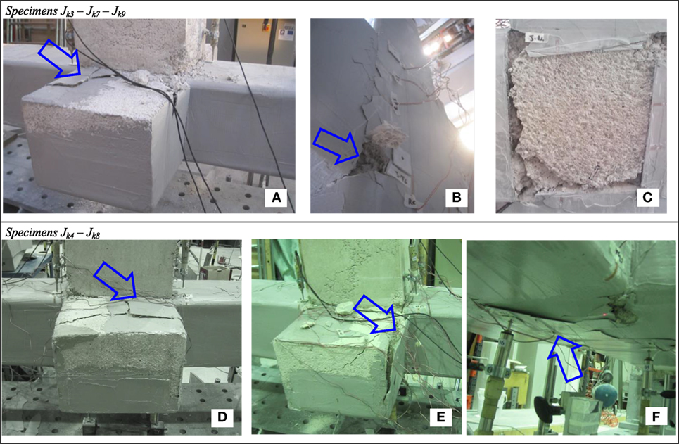
Figure 8. Crack pattern and failure for SRP strengthened specimens: JK3, JK7, and JK9 (A–C); JK4 and JK8 (D–F).
The CFRP strengthened specimens all exhibited the delamination of the external reinforcement which was delayed but not avoided by the use of mechanical steel anchors (Figures 7A,D,E,H). Of course, the occurrence of this phenomenon just above the anchorage steel plates was promoted by the opening of flexural cracks at the column-beam interface.
Figures 7B,C show the damage exhibited at the end of the test by the portions of the joint panel “J-06” “hidden” by the FRP: the typical diagonal cracks are clearly visible. For this member, it was also noted the beneficial contribution deriving by the arrangement of steel profiles on the joint’s exterior face which improved the out-of-plane stiffness. Indeed, in this case, the damage of the concrete cover caused by the push-in/pull-out action of the beam’s longitudinal steel rebars was strongly mitigated when compared with the damage observed for the specimens “J-07” and “J-08,” independently on the FRP layout (“x” or “vertical” pattern) used for the joint panel (see Figures 7F,I).
Furthermore, in all the performed tests, signs of damage were observed in the first 100 mm of the beam members, i.e., in the portion of concrete close to the column-beam interface. This phenomenon, mainly noted in the case of the specimen “J-08” (Figure 7G), was probably promoted by the local weakening induced with the installation of the mechanical anchors used for both steel plates and CFRP sheets.
In the case of SRP strengthened specimens, it is observed that, regardless of the considered layout (“cross” or “diagonal”), the SRP system preserved the column member from failure and strongly mitigated the damage exhibited by the joint panel up to high values of the imposed displacement (Figures 8B,F); conversely, the debonding of the “U” shape strip from the secondary beams (Figures 8A,D,E) and a progressive degradation of the concrete cover located at the main beam-column interface (Figure 8B), were noted. Also, during tests a large flexural crack, not clearly visible in the Figures, opened at the main beam base-section, thus implying that the use of the SRP strengthening systems contributed to moving the collapse from the joint panel toward the main beam (as desired in seismic areas); however, the failure of the beam was not achieved due to early occurrence of the loss of bond by main beam’s longitudinal steel reinforcement.
By removing the external strengthening (Figure 8C), it can be clearly noted the damage of the outer portion of the joint with the incipient detachment of the concrete cover by this was significantly reduced with respect to scenario observed in the case of CFRP strengthened specimens.
Cyclic Behavior
Figures 9A,B show the lateral force-displacement (F − Δ) cyclic curves and the corresponding monotonic envelopes for the unstrengthened members “J-05” and “Jk11”; these comparisons allow for investigating the influence of the confinement effect provided by the secondary beams on the joint performance. Even though the specimen “Jk11” is not truly representative of an existing beam-column joint due to the absence of shear and bending moment actions on the secondary beams, the comparisons show the significantly better behavior of such specimen with respect to the counterpart “J-05” in terms of both strength and deformation capacity, thus confirming what already found in the literature (Bedirhanoglu et al., 2010; Ilki et al., 2011). Particularly, the increases of the peak lateral load (Fmax) and deformation capacity at the conventional collapse of 15% strength decay were about 23 and 42%, respectively. This result has a relevant effect on the performance levels expected by the specimens strengthened with CFRP or SRP systems since these levels strongly depend on the cyclic responses exhibited by the respective control members. In other words, even when the external strengthening is missing, the addition of transverse beams is sufficient by itself to improve the overall performance of a shear-deficient joint (as mentioned earlier, no steel stirrups are arranged in the joint).
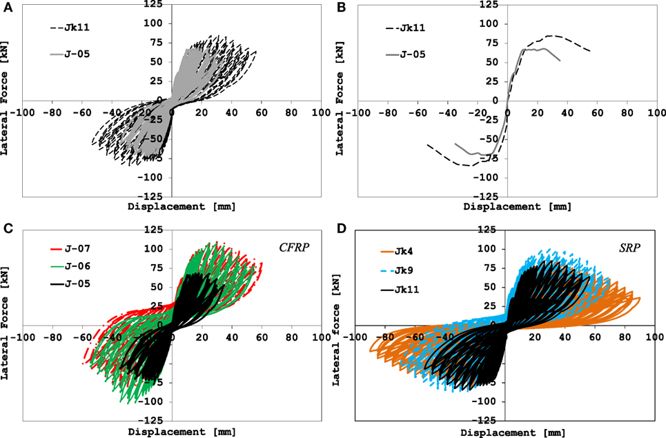
Figure 9. Load-displacement curves for: control specimens (A,B); CFRP strengthened specimens (C); SRP strengthened specimens (D).
It is highlighted that the improved shear capacity of the joint provided with transverse beams “Jk11” is in agreement with the analytical predictions obtained by applying some models found from the literature (ACI 352R-02, 2002; Kim and LaFave, 2008; Jeon et al., 2014).
As explained before, the beneficial effect is also proven by the crack pattern and failure mode experienced for the specimens “Jk1” and “Jk11” in comparison to those of the counterpart “J-05,” since in these cases the damage of the joint panel is significantly reduced whereas the column member is more prone to deteriorate.
The above considerations have to be kept in mind when comparing the F − Δ cyclic curves obtained for the CFRP strengthened specimens (Figure 9C) with the corresponding ones related to SRP strengthened members (Figure 9D). In particular, the experimental plots in Figure 9C refer to three representative beam-column subassemblies of the previous experimental campaign, i.e., “J-05,” unstrengthened; “J-06” and “J-07” strengthened according to the layouts of Figures 4A,B, respectively, which only differ for the presence/absence of steel profiles at the column corners. The cyclic curves shown in Figure 9D, instead, refers to three representative over the seven specimens included in the latest experimental program, i.e., “Jk11,” unstrengthened; “Jk9” and “Jk4” strengthened according to the layouts of Figures 3A,B, respectively.
By looking at the plot in Figure 9C, it is noted that, as already mentioned earlier, the experimental curves highlight a rather non-symmetric behavior in terms of lateral force. Also, in the case of the strengthened specimens and under high values of the imposed displacement, the cycles exhibit a shift toward the forces’ positive axis; this evidence is of course motivated by a non-uniform propagation of the crack pattern in the joint panel, being it partly confined by the steel plates simulating the presence of a floor slab.
Regardless of the use of steel profiles at the column corners, the comparisons highlight the effectiveness of the strengthening systems employed for the specimens “J-06” and “J-07.” Having designed these specimens according to a “strong-column” scheme, the experimental results have confirmed that the CFRP external confinement it sufficient by itself to avoid the premature failure of the column.
By looking at the plot in Figure 9D, it seems that, at a first glance, the examined SRP strengthening solutions provided a good performance with respect to the unstrengthened member but rather reduced when compared to that experienced in the case of CFRP systems. Indeed, although a less degrading post-peak behavior is noted for the SRP strengthened specimens with respect to the control member (“Jk11”) and confirmed by an appreciable increase of the deformation capacity (mainly when the “cross” pattern is employed), only a slight strength increase, sometimes over 10%, was observed (in this case specifically when the “cross” layout is used).
The seeming reduced performance of the SRP systems with respect to the control member was obtained because the full exploitation of the external strengthening was limited by the slip of the main beam’s longitudinal reinforcement. This evidence was: (a) confirmed during the cyclic tests through the opening of only one large flexural crack at the beam-column interface, and (b) theoretically verified since, by applying an analytical model available in the literature (Fib Bulletin No. 72, 2014), the value of the lateral force corresponding to the slippage of the steel reinforcement is in agreement with the experimental results obtained in the case of SRP strengthened members.
However, the use of the SRP system had a positive effect on the global response since it contributed to shifting the failure from the joint panel toward the main beam even though the loss of bond by longitudinal steel reinforcement occurred before such beam could failed.
In terms of deformation capacity, instead, the contribution of the external strengthening is more appreciable thanks to the capability of the SRP system of delaying the damage of specimens.
The overall performances obtained in the case of both CFRP and SRP strengthened specimens can be better compared by observing the F − Δ monotonic envelopes in Figure 10 and the values of the indices IF, IΔ85%, and IΔ75% reported in Table 3. These indices, giving an idea on the increases of strength and deformation capacity (at 15 and 25% strength decay) achievable by varying the strengthening solutions, were calculated through the following ratios:
where: and are the average values of the peak force in the two directions of loading for the strengthened and unstrengthened (test “J-05” or “JK11”) member, respectively; the displacements and are the average displacements Δ85% and Δ75% of the strengthened member in the two directions of loading, whereas the displacements and are the respective values for the member “J-05” or “JK11.”
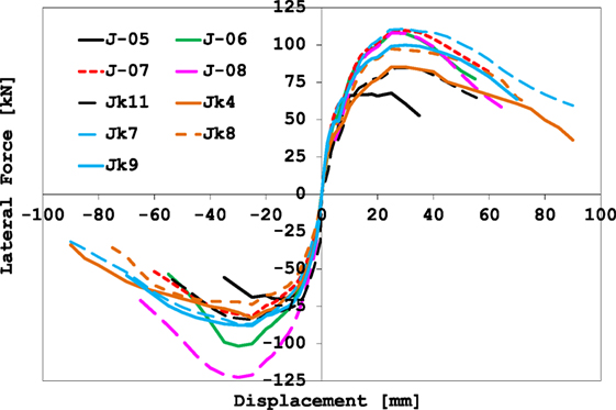
Figure 10. Load-displacement envelopes: comparison between SRP and CFRP strengthened specimens.
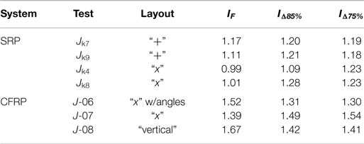
Table 3. Indices of strength and ductility.
The plot in Figure 10 shows that, regardless of the beam-column joint configuration (i.e., with or without the secondary beams), the initial stiffness of all the members is approximately the same; also, the load carrying capacity of the specimens strengthened with CFRP systems is more or less the same achieved by the counterparts strengthened by SRPs thus confirming that no additional load can be carried by the joints provided with secondary beams, despite the potential further contribution provided by SRP external strengthening.
To this purpose, the results reported in Table 3 show that, in the case of CFRP systems, the strength increases over the specimen “J-05” range between 39% (for the joint “J-07”) and 67% (for the joint J-08), in spite of lower values calculated in the case of SRP systems over the member “Jk11,” not greater than 17% (for the joint “Jk7”).
Conversely, looking at the post-peak branches of the F − Δ curves it seems that the SRP strengthened specimens exhibited a less degrading behavior with respect to the case of CFRP strengthened members where the collapse is achieved as soon as the abrupt delamination of the CFRP strip anchored to the main beam occurred. However, the ductility increases over the member “J-05” at 15% (or 25%) strength decrease are still significant, approximately spanning between 30% (for the joint “J-06”) and 50% (for the joint “J-07”). In the case of the SRP systems, instead, the ductility increases are in the range 10–28%.
Cyclic Behavior of Repaired and Retrofitted Specimens
As mentioned earlier, some specimens, after being damaged, were repaired, retrofitted with CFRP/SRP systems, and subjected to cyclic tests again.
The effectiveness of using the considered CFRP system to retrofit repaired RC beam-column subassemblies is clearly visible in Figures 11A,B where comparisons in terms of F–Δ cyclic curves and corresponding monotonic envelopes are shown for the specimens J-05 and J-05_R.
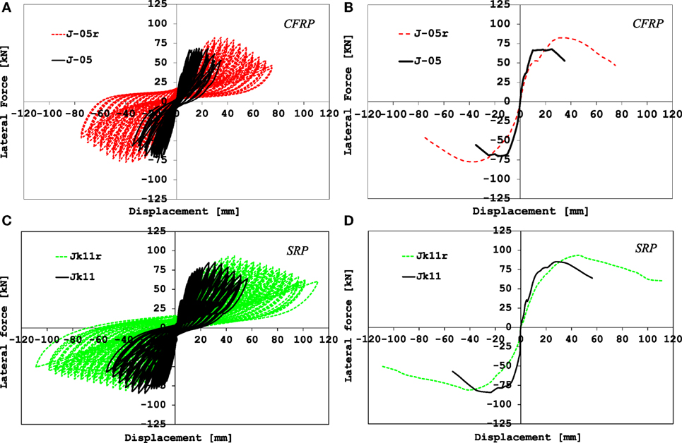
Figure 11. Effectiveness of the CFRP and SRP systems as retrofitting techniques: hysteresis loops (A,C) and envelopes (B,D).
As expected, the F–Δ response of the retrofitted member exhibits an initial stiffness lower than that of the corresponding member J-05. Conversely, the plots clearly highlight the beneficial effects produced by the employed strengthening systems not only in restoring but also in improving the performance of the “original” specimens mainly in terms of ductility. Indeed, as shown in Table 2, the specimen J-05_R was capable of increasing the flexural strength and the deformation capacity at 15% strength decay of about 16 and 75%, respectively. In this case, the confinement effect due to the use of continuous steel angles on the exterior face of the joint has strongly contributed to preserve its integrity up to high values of the imposed displacement.
The effectiveness of using the considered SRP system to retrofit repaired RC beam-column subassemblies is shown in Figures 11C,D where F–Δ cyclic curves and corresponding monotonic envelopes are plotted for the specimens Jk11 and Jk11r.
Also in this case, although the early stiffness was not restored, the specimen Jk11r exhibited the same strength performance of the counterpart Jk11 and even higher deformation capacity at both 15 and 25% strength decay (the increases of lateral displacement over the specimen Jk11 were approximately equal to 60 and 75%, respectively).
Of course, given the different typology of specimens tested in the previous and latest experimental campaign, it is not possible to provide an overall comment on the most suitable solution for retrofitting RC beam-column subassemblies. At the same time, by approximately calculating from the F–Δ monotonic envelopes, the slopes of the post-peak branches related to the specimens J-05r and Jk11r it seems that the examined SRP systems allow for a less degrading behavior of the specimen (the slope is 30% lower than the value computed for the specimen J-05r).
However, it is worth highlighting that the higher or lower strength and ductility performances expected by the use of CFRP or SRP systems is strongly influenced by the severity of damage exhibited by specimens before retrofitting. To this purpose, the strengthened specimen Jk9 can be considered which, after being severely damaged and repaired, was retrofitted with SRP by using the same layout previously used. In this case, during the second test the specimen was capable of achieving only about the 60% of the early strength even though the deformation capacity at the conventional collapse was approximately 30% higher (compare tests Jk9 and Jk9r in Table 2).
Stiffness Degradation and Energy Dissipation
Figures 12A,C show the experimental relationships between the mean value of the stiffness for the ith cycle (K) and the imposed displacement Δ. The K value was estimated by using the following ratio (Mayes and Clough, 1975):
where and are the beam lateral forces in the push and pull directions whereas and the corresponding displacements. The stiffness of each cycle was then normalized with respect to the stiffness of the first cycle KI and plotted in Figures 12B,D, thus providing a measure of the stiffness degradation.
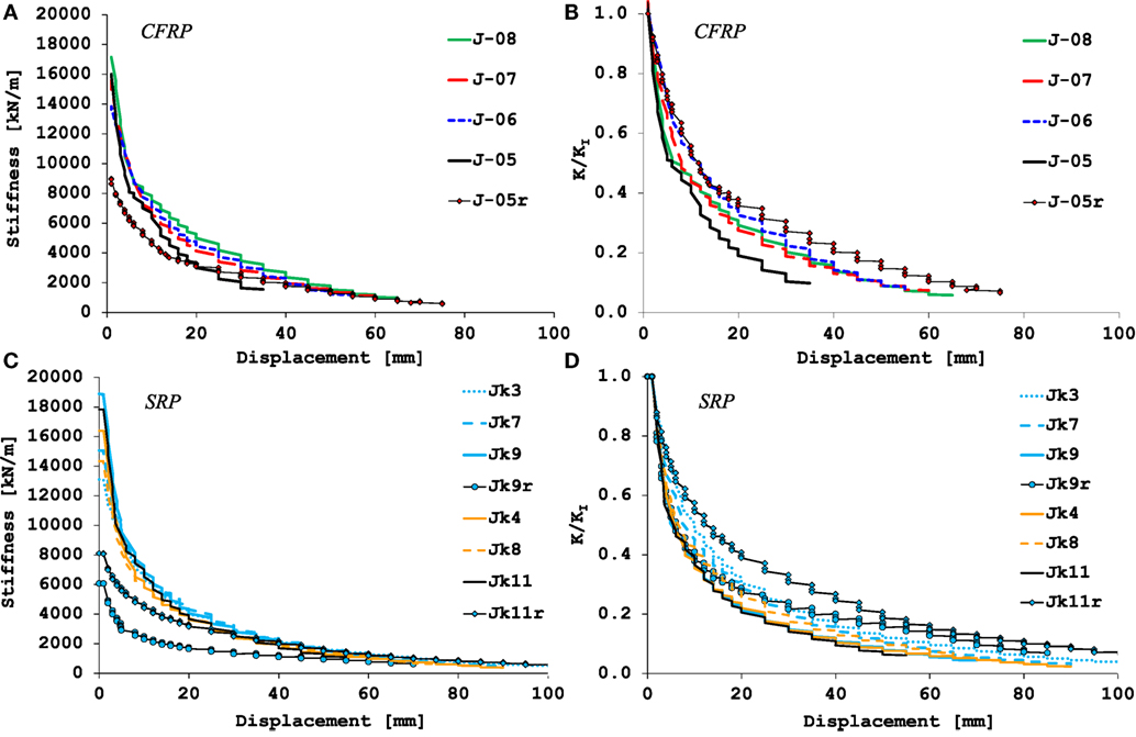
Figure 12. Stiffness degradation: CFRP strengthened specimens (A,B); SRP strengthened specimens (C,D).
In particular, the graphs in Figures 12A,B refer to specimens strengthened with CFRP systems whereas those in Figures 12C,D to members strengthened with SRPs.
As already highlighted, in the case of tests performed on “2D” joints, a clearer difference in terms of stiffness degradation exists between the control member and the counterpart strengthened with CFRP systems. Indeed, although the use of the external strengthening does not imply a modification of the initial stiffness of the specimens (see, Figure 12A), the reference joint J-05 showed a faster stiffness degradation with the imposed displacement (see, Figure 12B). Among the CFRP strengthened specimens, it is noted that the joint J-06 exhibited a more gradual reduction of the stiffness thanks to the confinement effect provided by the continuous steel profiles which delayed the concrete spalling.
By focusing on the repaired joint J-05r, it is observed that, although the initial stiffness was about half of the KI value estimated for the specimen J-05, the use of the CFRP strengthening system had a significant effect on the stiffness degradation which was strongly mitigated.
Tests performed on “3D” joints have highlighted that the initial stiffness has not remarkably changed in comparison to the previous tests nor the application of the SRP strengthening system has a relevant effect. At the same time, since the unstrengthened joints Jk1 and Jk11 already exhibited a better cyclic behavior with respect to the “2D” counterpart, the stiffness degradation of the SRP strengthened members is only slightly improved at a given imposed displacement. Of course, the SRP strengthened specimens are capable of undergoing higher displacement at conventional collapse (see, Figures 12C,D).
Finally, by focusing on the joints Jk9r and Jk11r similar considerations to those made for the specimen J-05r can be made.
The relationships between the cumulative dissipated energy (E) and the imposed beam displacement are shown in Figures 13A,B for specimens strengthened with CFRP and SRP systems, respectively; this energy parameter was calculated—at each imposed displacement—from the area under the F–Δ response enclosed within one complete cycle up to the end of each test.
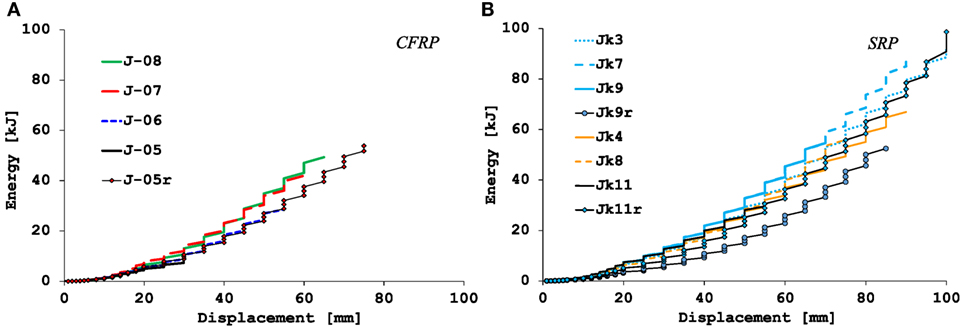
Figure 13. Energy dissipation: CFRP strengthened specimens (A); SRP strengthened specimens (B).
From both diagrams, it is observed that the external strengthening always provided a significant increase of the total dissipated energy as higher displacements were exhibited at collapse of the specimens; however, the cumulative energy dissipated up to a given value of Δ is only slightly higher than that of the unstrengthened members.
Conclusion
In this paper, the results of cyclic tests carried out on exterior RC beam-column joints strengthened by SRP systems have been discussed. Specimens were designed to be representative of façade frames’ beam-column subassemblies which are frequently found in existing RC buildings. In order to simulate the presence of transverse beams, two small concrete stubs orthogonal to the main beam were considered.
The performances have been analyzed through a comparison with the results from tests performed on counterparts strengthened with CFRP systems but not provided with transverse concrete stubs (“2D joints”).
The comparison has first highlighted the influence of the joint’s confinement effect from the secondary beams on the crack pattern and failure mode exhibited by tested specimens even without the external SRP strengthening. Indeed, even though the joint panel of the control member experienced severe damage, this was not comparable with that shown by the counterpart not provided with secondary beams.
The influence of the secondary beams is also recognizable in the load-displacement response exhibited; the increases of peak lateral load and deformation capacity over the “2D” joint were about 23 and 42%, respectively.
Of course, the different behavior experienced by the two considered unstrengthened members has an effect on the performance levels expected by the companion specimens strengthened with CFRP or SRP systems, being the addition of transverse beams sufficient by itself to improve the overall performance of a shear-deficient joint. To this purpose, it has been shown that the load carrying capacity of the specimens strengthened with CFRP systems is more or less the same achieved by the counterparts strengthened by SRPs; however, it has to be noted that, in the case of SRP strengthened specimens, the opening of only one large flexural crack at the main beam-column interface highlighted a loss of bond of the main beam’s longitudinal reinforcement which did not allow the main beam for carrying a higher load level to transfer to the joint.
Despite this considerations, the SRP strengthened specimens exhibited a strength increase over the control member not greater than 17%, whereas the ductility increases are in the range 10–28%; the upgrading of the joint panel by using the “cross” layout which offers easier installation, also resulted more effective than the “diagonal” one.
Like the FRPs, the SRP systems have highlighted their effectiveness also in retrofitting damaged members; indeed, in some cases they allowed for significantly increasing the deformation capacity and, in some cases, even restoring the strength of the early specimens.
Author Contributions
ADV and AN contributed to all the steps needed to the article production, from conceiving, designing, and performing tests, to analyzing the experimental results, and writing the paper. RR supervised all the steps needed to the article production, from conceiving, designing, and performing tests, to analyzing the experimental results and writing the paper.
Conflict of Interest Statement
The authors declare that the research was conducted in the absence of any commercial or financial relationships that could be construed as a potential conflict of interest.
Acknowledgments
The authors gratefully acknowledge “Interbau S.r.l.” (Milan, Italy) and “Kerakoll S.p.A.” (Sassuolo, Italy) for the technical and financial support to the experimental programs related to RC-beam column joints strengthened with CFRP and SRP systems, respectively. The experimental program on the use of SRP systems has also been financially supported by ReLUIS-Italian Department of Civil Protection’s Executive Project 2016. Special thanks are extended to Eng. Francesco Perri for his precious assistance in the laboratory work.
Footnotes
References
ACI 352R-02. (2002). Recommendations for Design of Beam-Column Connections in Monolithic Reinforced Concrete Structures. Joint ACI-ASCE Committee 352. Farmington Hills, MI, 45.
Akguzel, U., and Pampanin, S. (2012). Assessment and design procedure for the seismic retrofit of reinforced concrete beam-column joints using FRP composite materials. J. Compos. Constr. 16, 21–34. doi:10.1061/(ASCE)CC.1943-5614.0000242
Al-Salloum, Y. A., Siddiqui, N. A., Elsanadedy, H. M., Abadel, A. A., and Aqel, M. A. (2011). Textile-reinforced mortar versus FRP as strengthening material for seismically deficient RC beam-column joints. J. Compos. Constr. 15, 920–933. doi:10.1061/(ASCE)CC.1943-5614.0000222
Antonopoulos, C. P., and Triantafillou, T. C. (2003). Experimental investigation of FRP-strengthened RC beam-column joints. J. Compos. Constr. 7, 39–49. doi:10.1061/(ASCE)1090-0268(2003)7:1(39)
Bedirhanoglu, I., Ilki, A., Pujol, S., and Kumbasar, N. (2010). Behavior of deficient joints with plain bars and low-strength concrete. ACI Struct. J. 107, 300–310. doi:10.14359/51663695
Bousselham, A. (2010). State of research on seismic retrofit of RC beam-column joints with externally bonded FRP. J. Compos. Constr. 14, 49–61. doi:10.1061/(ASCE)CC.1943-5614.0000049
De Santis, S., de Felice, G., Napoli, A., and Realfonzo, R. (2016). Strengthening of structures with Steel Reinforced Polymers: a state-of-the-art review. Compos. Part B Eng. 104, 87–110. doi:10.1016/j.compositesb.2016.08.025
Del Vecchio, C., Di Ludovico, M., Balsamo, A., Prota, A., Manfredi, G., and Dolce, M. (2014). Experimental investigation of exterior RC beam-column joints retrofitted with FRP systems. J. Compos. Constr. 18, 1–13. doi:10.1061/(ASCE)CC.1943-5614.0000459
Decreto Ministeriale 14 gennaio. (2008). Norme Tecniche per le Costruzioni, G.U. n.29, Supplemento Ordinario n. 30, Rome (in Italian).
DPC/Reluis. (2011). “Guidelines for repair and strengthening of structural elements, infill and partitions (in Italian),” in: Doppiavoce 2011, eds M. Dolce and G. Manfredi, 194.
El-Amoury, T., and Ghobarah, A. (2002). Seismic rehabilitation of beam–column joint using GFRP sheets. Eng. Struct. 24, 1397–1407. doi:10.1016/S0141-0296(02)00081-0
Engindeniz, M., Kahn, L. F., and Zureick, A. H. (2005). Repair and strengthening of reinforced concrete beam-column joints: state of the art. ACI Struct. J. 102, 187–197. doi:10.14359/14269
Fib Bulletin No. 72. (2014). Bond and Anchorage of Embedded Reinforcement: Background to the Fib Model Code for Concrete Structures 2010. Lausanne, CH: Technical Report, 1–170.
Ghobarah, A., and El-Amoury, T. (2005). Seismic rehabilitation of deficient exterior concrete frame joints. J. Compos. Constr. 9, 408–416. doi:10.1061/(ASCE)1090-0268(2005)9:5(408)
Ilki, A., Bedirhanoglu, I., and Kumbasar, N. (2011). Behavior of FRP-retrofitted joints built with plain bars and low-strength concrete. J. Compos. Constr. 15, 312–326. doi:10.1061/(ASCE)CC.1943-5614.0000156
Izi, R., Elbadry, M., and Ibrahim, H. (2008). “Steel Reinforced Polymers enhance strength and ductility of beam-column joints under seismic loads,” in Proceedings of ASCE 2008 Structures Congress (Vancouver, BC).
Jeon, J. S., Shafieezadeh, A., and Reginald, D. R. (2014). Statistical models for shear strength of RC beam-column joints using machine-learning techniques. Earthq. Eng. Struct. Dyn. 43, 2075–2095. doi:10.1002/eqe.2437
Kim, J., and LaFave, J. M. (2008). “Joint shear behavior prediction in RC beam-column connections subjected to seismic lateral loading,” in Proceedings of the 14th World Conference on Earthquake Engineering (Beijing, China).
Mayes, R. L., and Clough, R. W. (1975). State of the Art in Seismic Shear Strength of Masonry – An Evaluation and Review. EERC Report 1975. Berkeley, CA.
Napoli, A., de Felice, G., De Santis, S., and Realfonzo, R. (2016). Bond behaviour of Steel Reinforced Polymer strengthening systems. Compos. Struct. 152, 499–515. doi:10.1016/j.compstruct.2016.05.052
Napoli, A., and Realfonzo, R. (2015). RC columns strengthened with novel CFRP systems: an experimental study. Polymers 7, 2044–2060. doi:10.3390/polym7101499
Realfonzo, R., and Napoli, A. (2009). Cyclic behavior of RC columns strengthened by FRP and steel devices. J. Struct. Eng. 135, 1164–1176. doi:10.1061/(ASCE)ST.1943-541X.0000048
Realfonzo, R., and Napoli, A. (2012). Results from cyclic tests on high aspect ratio RC columns strengthened with FRP systems. Constr. Build. Mater. 37, 606–620. doi:10.1016/j.conbuildmat.2012.07.065
Realfonzo, R., Napoli, A., and Ruiz Pinilla, J. G. (2014). Cyclic behavior of RC beam-column joints strengthened with FRP systems. Constr. Build. Mater. 54, 282–297. doi:10.1016/j.conbuildmat.2013.12.043
Sasmal, S., Ramanjaneyulu, K., Novák, B., Srinivas, V., Kumar, K. S., Korkowski, C., et al. (2011). Seismic retrofitting of nonductile beam-column sub-assemblage using FRP wrapping and steel plate jacketing. Constr. Build. Mater. 25, 175–182. doi:10.1016/j.conbuildmat.2010.06.041
Sikadur. (2015). Sikadur30 Adhesive for Bonding Reinforcement. Available at: http://www.sika.com
Keywords: reinforced concrete beam-column joints, seismic upgrade, SRP/FRP, experimental tests, strength, ductility
Citation: De Vita A, Napoli A and Realfonzo R (2017) Full Scale Reinforced Concrete Beam-Column Joints Strengthened with Steel Reinforced Polymer Systems. Front. Mater. 4:18. doi: 10.3389/fmats.2017.00018
Received: 24 May 2017; Accepted: 16 June 2017;
Published: 27 July 2017
Edited by:
Yu-Fei Wu, RMIT University, AustraliaReviewed by:
Theodoros Chris Rousakis, Democritus University of Thrace, GreeceAlper Ilki, Istanbul Technical University, Turkey
Copyright: © 2017 De Vita, Napoli and Realfonzo. This is an open-access article distributed under the terms of the Creative Commons Attribution License (CC BY). The use, distribution or reproduction in other forums is permitted, provided the original author(s) or licensor are credited and that the original publication in this journal is cited, in accordance with accepted academic practice. No use, distribution or reproduction is permitted which does not comply with these terms.
*Correspondence: Roberto Realfonzo, rrealfonzo@unisa.it