Reducing Diesel Engine Drive Cycle Fuel Consumption through Use of Cylinder Deactivation to Maintain Aftertreatment Component Temperature during Idle and Low Load Operating Conditions
 Mrunal C. Joshi1
 Dheeraj B. Gosala1
 Cody M. Allen1
 Kalen Vos1
Matthew Van Voorhis1
Kalen Vos1
Matthew Van Voorhis1
 Alexander Taylor1
 Gregory M. Shaver1*
James McCarthy Jr.2
Dale Stretch2
Edward Koeberlein3
Lisa Farrell3
Gregory M. Shaver1*
James McCarthy Jr.2
Dale Stretch2
Edward Koeberlein3
Lisa Farrell3
- 1Purdue University, West Lafayette, IN, United States
- 2Eaton, Galesburg and Marshall, Galesburg, MI, United States
- 3Cummins Technical Center, Columbus, IN, United States
Modern on-road diesel engine systems incorporate flexible fuel injection, variable geometry turbocharging, high pressure exhaust gas recirculation, oxidation catalysts, particulate filters, and selective catalytic reduction systems in order to comply with strict tailpipe-out NOx and soot limits. Fuel consuming strategies, including late injections and turbine-based engine exhaust throttling, are typically used to increase turbine-outlet temperature and flow rate in order to reach the aftertreatment component temperatures required for efficient reduction of NOx and soot. The same strategies are used at low load operating conditions to maintain aftertreatment temperatures. This paper demonstrates that cylinder deactivation (CDA) can be used to maintain aftertreatment temperatures in a more fuel-efficient manner through reductions in airflow and pumping work. The incorporation of CDA to maintain desired aftertreatment temperatures during idle conditions is experimentally demonstrated to result in fuel savings of 3.0% over the HD-FTP drive cycle. Implementation of CDA at non-idle portions of the HD-FTP where BMEP is below 3 bar is demonstrated to reduce fuel consumption further by an additional 0.4%, thereby resulting in 3.4% fuel savings over the drive cycle.
1. Introduction
Tailpipe limits for heavy-duty on-highway diesel engines in the United States are currently 0.2, 0.01, and 0.14 g/bhp-hr for oxides of nitrogen (NOx), particulate matter (PM), and unburned hydrocarbons (UHC), respectively (United States Environmental Protection Agency, 2010). Diesel engine emission control systems incorporate both on-engine and aftertreatment system strategies. The aftertreatment system typically includes a diesel oxidation catalyst (DOC), diesel particulate filter (DPF), and selective catalytic reduction (SCR) system. The DOC converts UHC to carbon dioxide and water, the DPF traps PM, and the SCR system reduces NOx. The integrated aftertreatment system generally requires operating temperatures in excess of 200°C to work effectively, requiring the implementation of “thermal management” to reach, and maintain, desirable operating temperatures (Blakeman et al., 2003; Song et al., 2007; Charlton et al., 2010; Hou et al., 2010; Gehrke et al., 2013; Stadlbauer et al., 2013).
Conventional diesel engine aftertreatment thermal management strategies include late in-cylinder fuel injections, intake air valve throttling, exhaust gas throttling (using a valve or variable geometry turbine turbocharger), and oxidation catalyst fuel dosing. All of these strategies, while being effective in accelerated warm-up of aftertreatment components, also result in increased fuel consumption (Maiwald et al., 2010).
Cylinder deactivation (CDA) has been generally associated with improved fuel efficiency via reduction in pumping work. In gasoline engines, CDA has been extensively studied to improve fuel efficiency at low speeds and low loads via reduced throttling losses (Leone and Pozar, 2001; Falkowski et al., 2004). CDA in gasoline engines has also been implemented in production vehicles—for example, GM’s V-6 and V-8 engines use CDA to obtain up to 5% better fuel economy (McCarthy, 2016), while Honda implemented CDA in their 3.5L V6 engine to reduce fuel consumption by 7%.
CDA in diesel engines can also improve fuel consumption by decreasing pumping losses and improving brake thermal efficiency. A fuel consumption improvement of 5–25% on a diesel engine was demonstrated by implementing CDA at low load steady-state operating conditions (Ramesh et al., 2017). Ding et al. (2015) experimentally demonstrated that CDA combined with other VVA strategies, including late intake valve closing (LIVC) and internal EGR (iEGR), at lightly loaded and loaded idle conditions, enable an improved trade-off between fuel economy and thermal management in comparison with conventional thermal management strategies. CDA has been shown to result in exhaust temperatures capable of passive DPF regeneration during highway cruise conditions (Lu et al., 2015).
This paper demonstrates CDA as a competitive strategy to simultaneously reduce fuel consumption and maintain aftertreatment system temperatures via implementation at loaded idle conditions and at appropriate sections of the HD-FTP where BMEP < 3 bar, thereby establishing CDA as an effective method to improve the trade-off between fuel consumption and tail pipe out NOx emissions.
2. Experimental Setup
Experimental data presented here were acquired on an in-line six-cylinder Cummins diesel engine equipped with an electro-hydraulic variable valve actuation (VVA) system. An AC dynamometer enables both steady-state and transient drivecycle testing.
2.1. Engine Configuration and Instrumentation
The engine is equipped with a common rail fuel injection system, high pressure cooled exhaust gas recirculation (EGR) and variable geometry turbine (VGT) turbocharging. Figure 1 shows a schematic of the air handling system of the engine.
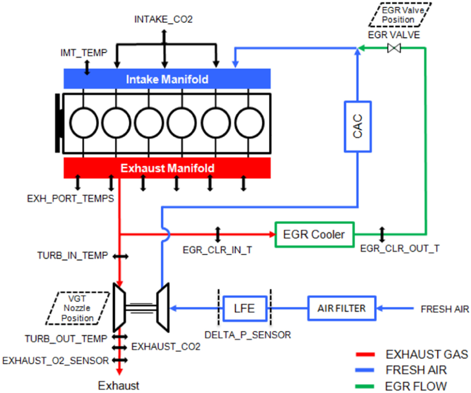
Figure 1. Schematic of the air handling system of the engine indicating the positions of relevant actuators and sensors.
In-cylinder pressures are acquired for each of the six-cylinders using Kistler 6067C and AVL QC34C pressure transducers through an AVL 621 Indicom module. Fresh air flow into the engine is measured using a laminar flow element. Fuel flow is measured gravimetrically using a Cybermetrix Cyrius Fuel Subsystem (CFS) unit. Intake and exhaust CO2 concentrations are measured using Cambustion NDIR500 analyzers, allowing for calculation of EGR fraction. A Cambustion fNOx400 fast analyzer is used to measure NOx concentration. CO2 and NOx concentrations are also measured using California Analytical Instruments NDIR600 and HCLD600 analyzers, respectively. Unburnt hydrocarbons are measured using a CAI HFID600 analyzer.
Coolant, oil, and gas temperatures at various locations are measured using thermocouples. Data are monitored and logged through a dSPACE interface. The engine control module (ECM) is connected to the dSPACE system through a generic serial interface (GSI) link that allows cycle-to-cycle monitoring and control of fueling and various other engine functions.
2.2. Variable Valve Actuation System
A schematic of the VVA system is shown in Figure 2. The electro-hydraulic variable valve actuation (VVA) system allows flexible, cylinder-independent, cycle-to-cycle control of valve operation. Each intake and exhaust valve pair is actuated independently. Position feedback for each valve pair is measured using a linear variable differential transformer (LVDT). A real-time controller is implemented in dSPACE to control valve actuation.
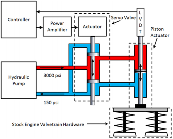
Figure 2. Schematic of the variable valve actuation system.
Valve profiles for active cylinders in this work are kept the same as stock valve profiles, as shown in Figure 3. Three cylinder CDA is achieved by deactivating the fuel injection and valve motions for cylinders 4, 5, and 6, as illustrated in Figure 4. Fueling is increased (nearly doubled) in the three activated cylinders to maintain brake torque.
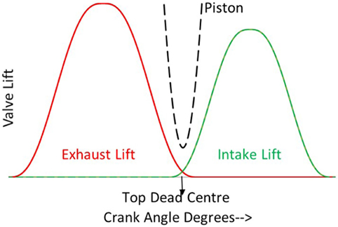
Figure 3. Intake and exhaust valve profiles with a conventional cam shaft.
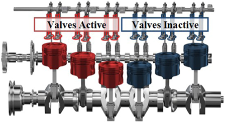
Figure 4. Deactivated cylinders have no fuel injections and have their valves shut during CDA. The amount of fuel injected doubles for the active cylinders in CDA to be able to meet the required brake torque.
2.3. Aftertreatment System
Figure 5 shows a schematic of the aftertreatment (A/T) system in the test setup. The diesel oxidation catalyst (DOC) oxidizes unburnt hydrocarbons and carbon monoxide to form carbon dioxide and water. The diesel particulate filter (DPF) physically traps particulate matter and the selective catalytic reduction (SCR) system promotes the reaction between injected urea, oxides of nitrogen (NOx) and other species in the exhaust to form nitrogen and water (Koebel et al., 2000). The SCR system in the experimental test bed has been presently set up for passive operation without any urea injection.
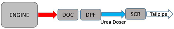
Figure 5. A diesel engine aftertreatment (A/T) system consists of discrete emission reducing modules, along with a urea injection system and required instrumentation like thermocouples and emission measurements. Note that the SCR in the test setup is currently used in the passive mode without any urea injection.
3. Efficiency Analysis
Engine cycle efficiency analysis is implemented to better understand the impact of CDA and conventional A/T thermal management strategies. Open cycle efficiency (OCE) captures the efficiency of the gas exchange process, closed cycle efficiency (CCE) represents the effectiveness of combustion and mechanical efficiency (ME) captures frictional and accessory losses (Stanton, 2013). The three efficiencies contribute to the brake thermal efficiency (BTE) as shown in equation (1) (for more information see Stanton et al. (2013)).
4. Aftertreatment (A/T) Thermal Management Relevance of Idle During HD-FTP
Section 1065.530 of the EPA Code of Federal Regulations (United States Environmental Protection Agency, 2017) specifies the test sequence for the HD-FTP drivecycle to include a cold start cycle, soak, and hot start cycle, as shown in Figure 6. The cycle fuel consumption, cumulative engine-outlet NOx, and cumulative tailpipe NOx for the test sequence are calculated through weighted summation of the fuel consumption, cumulative engine-outlet NOx, and cumulative tailpipe NOx of the cold start and hot start cycles. The cold start is weighted by a factor of 1/7 and the hot start has a weighting factor of 6/7 (United States Environmental Protection Agency, 2017).
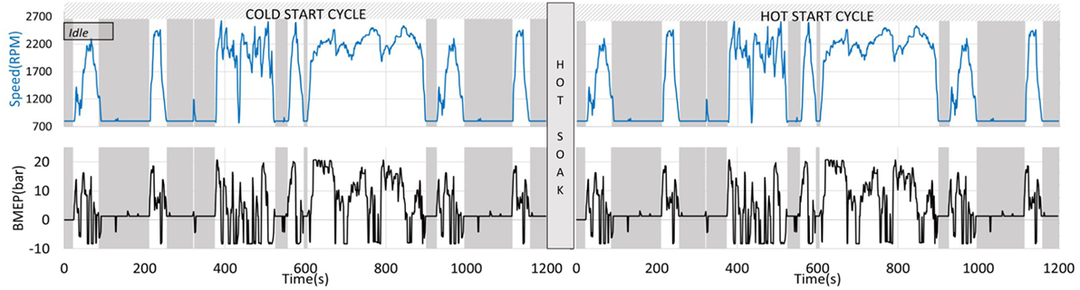
Figure 6. Speed and torque profiles for the HD-FTP show that nearly 40% of the HD-FTP operation occurs at idle conditions. Shaded gray areas highlight the idle (800 RPM/1.3 bar) sections while correspond to BMEP < 3 bar where CDA can potentially be implemented.
Figure 6 shows that approximately 40% of HD-FTP cycle is spent at idle, here assumed to be 800 RPM/1.3 bar BMEP, which is consistent with a conventional mid-range application. Engine-outlet temperatures and exhaust flow rates during this condition, therefore, have a significant impact on the ability of the engine to heat, maintain, or cool the A/T components to desirable levels.
The following section discusses, in detail, the fuel consumption, engine-outlet temperature, exhaust flow rate, and emission performance of both conventional six-cylinder and half engine CDA operating modes during steady-state idle. The aim is to provide a comparison of A/T thermal management performance of conventional six-cylinder engine strategies and half engine CDA at idle conditions.
5. Results—800 RPM/1.3 Bar Idle Operating Strategies for A/T Thermal Management: Warm-Up and Stay-Warm
Both elevated engine-outlet temperatures and exhaust flow rates are desirable to increase A/T component temperatures. The engine-outlet temperature must be at least 200°C to warm-up the A/T components to 200°C, with higher exhaust flow rates (or engine-outlet temperatures) accelerating the warm-up process. Once the A/T components have reached desirable temperatures, elevated engine-outlet temperatures are required to maintain those temperatures; however, elevated exhaust flow rates are no longer necessary. Lower exhaust flow rates are preferred in order to reduce cooling effects in case engine-outlet temperatures drop below the temperature of a sufficiently warmed-up A/T system. This section emphasizes on steady-state engine operation, while comparisons during transient engine operation (over the HD-FTP drive cycle) are detailed in a later section. The aforementioned A/T warm-up/stay-warm impacts of engine-outlet temperature and exhaust flow rate for the following four operating strategies at steady-state idle (800 RPM/1.3 bar) are compared in this section.
1. Six-cylinder best engine efficiency idle—conventional six-cylinder engine operation targeting best brake specific fuel consumption (BSFC). This strategy implements fuel-efficient injection profiles with a heat release beginning near top dead center and is characterized by low engine-outlet temperature and exhaust flow rate, both inconsistent with A/T warm-up or stay-warm operation. The “Six-cylinder best engine efficiency idle” strategy is included here as a baseline to demonstrate the fuel consumption increases typically required in conventional engine systems in order to increase, and maintain, desirable A/T temperatures for current tailpipe emissions compliance.
2. Six-cylinder A/T warm-up idle—conventional six-cylinder engine operation with a focus on increasing A/T temperature. This strategy uses a completely closed VGT and four late injections (which result in a fuel-inefficient delayed heat release) to increase engine-outlet temperatures and exhaust flow rate for accelerated A/T warm-up, albeit at the expense of increased fuel consumption.
3. Six-cylinder A/T stay-warm idle—conventional six-cylinder engine operation with focus on maintaining elevated A/T temperatures while being as fuel efficient as possible. Similar to the “Six-cylinder A/T warm-up idle” strategy, this strategy implements the fuel-inefficient delayed heat release to maintain elevated engine-outlet temperatures for A/T stay-warm operation and incorporates a mostly closed VGT to improve fuel efficiency, relative to the “Six-cylinder A/T warm-up idle” strategy, via reduced pumping losses.
4. Half-engine CDA A/T stay-warm idle—Three cylinder engine operation allows maintenance of desirable A/T temperatures in a more fuel-efficient manner than that possible via the “Six-cylinder A/T stay-warm idle” strategy. Deactivation of three cylinders decreases the airflow (but not below levels required for complete, low smoke, combustion), increasing engine-outlet temperature (via reduced air-to-fuel ratio) in a fuel-efficient manner (due to lower pumping work). This strategy has sufficiently elevated engine-out temperatures, and lower exhaust flow rate, which help in decreasing the rate at which warmed-up A/T components cool-down later in the drive cycle.
The first two strategies correspond to stock engine operation in cases where the aftertreatment system: (i.) is fully warmed-up already and (ii.) requires thermal management, respectively. The EGR valve position and rail pressure for the last two strategies were modified to realize engine-out NOx, unburnt hydrocarbons, and PM consistent with the stock strategies. Total fueling quantities were modified to meet the desired torque. Tests were carried out with strict adherence to the mechanical constraints shown in Table 1.
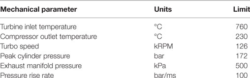
Table 1. Mechanical constraints.
Figure 7 compares injection profiles used for each of the strategies described above. The “Six-cylinder best engine efficiency idle” strategy incorporates fuel injections, and subsequent heat release, near TDC (per Figure 7A), as this is consistent with low fuel consumption. To achieve elevated engine-outlet temperatures the “Six-cylinder A/T warm-up idle” and “Six-cylinder A/T stay-warm idle” strategies use four delayed injections, and subsequent delayed heat releases (per Figures 7B,C). The “Half-engine CDA A/T stay-warm idle” strategy enables desirable elevated engine-outlet temperatures (via lower air-to-fuel ratio through air flow reductions) with two late injections (instead of four late injections) (per Figure 7D). Note that this is not the most fuel-efficient strategy for Half-engine CDA at this operating point and is still more efficient than the most efficient 6-cylinder operating strategy.
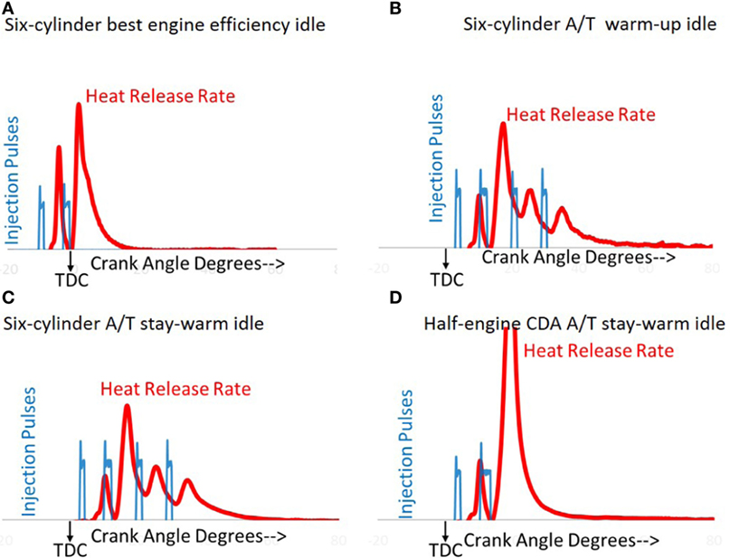
Figure 7. Experimental fuel injector current and heat release for the four strategies during 800 RPM/1.3 bar operation. The “Six-cylinder best engine efficiency idle” strategy (A) has two early injections while strategies involving six-cylinder operation in thermal management strategy (B,C) have four late injections to obtain elevated turbine-outlet temperature. Two delayed injections are used for the “Half-engine CDA A/T stay-warm idle” strategy (D) to maintain desirable A/T temperatures in a fuel-efficient manner.
Figure 8 illustrates that the “Six-cylinder A/T warm-up idle” strategy has the highest engine-outlet temperature (260°C) and exhaust flow rate, both of which are preferred for warming up the A/T components— at the expense of the highest fuel consumption. By comparison, the “Six-cylinder best engine efficiency idle” strategy has lower fuel consumption along with much lower engine-outlet temperature (146°C) and lower exhaust flow, both of which are inadequate for either A/T warm-up or A/T stay-warm operation. This comparison demonstrates the fuel penalty typically required during conventional six-cylinder diesel engine operation to meet A/T thermal management requirements.
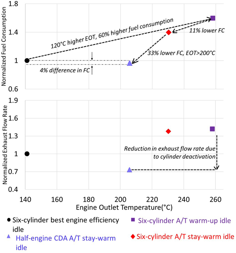
Figure 8. Experimental results from 800 RPM/1.3 bar idle. “Six-cylinder A/T warm-up idle” strategy enables fast A/T warm-up via elevated engine-outlet temperatures and flow rates, albeit at the expense of increase fuel consumption. The “Half-engine CDA A/T stay-warm idle” strategy enables fuel-efficient A/T component temperature maintenance via elevated engine-outlet temperatures, low exhaust flow rate, and low fuel consumption.
Once the A/T components have reached desirable temperatures (as will be shown later, approximately 40% of the way through the HD-FTP) a more fuel-efficient operating strategy with lower engine-outlet temperature or exhaust flow rate is preferred for A/T temperature maintenance. The “Six-cylinder A/T stay-warm idle” strategy shown in Figure 8 is an example of such an operating strategy, with 11% fuel savings, at the expense of a 20°C lower engine-outlet temperature. Note that this strategy still has a substantially higher fuel consumption than the “Six-cylinder best engine efficiency idle” strategy, since it incorporates late injections, and a mostly closed VGT.
Figure 8 demonstrates that CDA allows an engine-outlet temperature in excess of 200°C and the lowest exhaust flow rate, with a fuel consumption that is 40, 33, and 4% lower than the “Six-cylinder A/T warm-up idle,” “Six-cylinder A/T stay-warm idle,” and “Six-cylinder best engine efficiency idle” strategies, respectively. The “Half-engine CDA A/T stay-warm idle” strategy is, therefore, a preferred fuel-efficient strategy for maintaining A/T above approximately 200°C. The reduced exhaust flow rate (via reduced displaced volume) decreases the rate of cool-down of the A/T components while A/T temperatures exceed 200°C. In other words, of the four operating strategies, the “Half-engine CDA A/T stay-warm idle” strategy is preferred for fuel-efficient maintenance of elevated A/T component temperatures. This will be demonstrated over the HD-FTP in a subsequent section of this paper.
Figure 9 illustrates, for each of the four idle strategies, an approximation of the relative heat transfer rate from the engine-outlet gas to the A/T system catalyst beds. Treating the DOC, DPF, and SCR catalyst beds as one lumped mass at an instantaneous temperature Tbed, the heat transfer rate can be approximated using equation (2) (Ding et al., 2015).
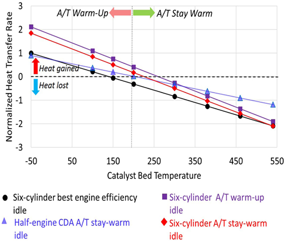
Figure 9. Estimated normalized heat transfer results for the four strategies at 800 RPM/1.3 bar. Catalyst warm-up is fastest during the “Six-cylinder A/T warm-up idle” strategy. Once catalyst temperatures reach desirable temperature (e.g., 300 deg. C), the “Half-engine CDA A/T stay-warm idle” strategy is preferred given its lower exhaust flow rate, and elevated engine-outlet temperature.
is the engine-outlet gas flow rate, Texh is the engine-outlet gas temperature, and C is a constant that depends on the geometry and material of the catalyst.
This simple model yields an approximate heat transfer rate from the exhaust gas to the A/T system, for a given effective bed temperature, as a function of the experimentally measured engine-outlet flow rate and temperature for each of the four idle strategies. A positive heat transfer rate corresponds to catalyst warm-up, as heat is transferred from the exhaust gas to the catalyst. A negative heat transfer rate corresponds to catalyst cool-down, as the heat is transferred from the catalyst to the exhaust gas. The normalized heat transfer rate continues to be positive as long as the catalyst bed temperature Tbed is below the engine-outlet gas temperature Texh and catalyst warm-up occurs. The normalized heat transfer rate is negative when Tbed is above Texh and catalyst cool-down occurs. The “zero crossing” in Figure 9, for each of the four strategies, therefore, corresponds to the Texh for the corresponding strategy. Per equation (2), the slope of the normalized heat transfer lines in Figure 2 is proportional to . The line slopes are, therefore, steeper for higher exhaust flow rates. As a result, and consistent with expectation, a higher exhaust flow rate results in a higher rate of warm-up when Tbed is lower than the Texh. However, a higher exhaust flow rate corresponds to a faster cool-down of the catalyst when Tbed is higher than Texh. As a result, Figure 2 shows that for catalyst temperatures below approximately 200°C, the “Six-cylinder A/T warm-up idle” strategy is preferred. However, for catalyst temperatures above approximately 200°C, the “Half-engine CDA A/T stay-warm idle” strategy is preferred since it can cool-down the catalyst more slowly than the other strategies, and simultaneously consume less fuel.
In summary, Figure 9 demonstrates that: (i) the “Six-cylinder A/T warm-up idle” strategy is preferred for A/T warm-up and, (ii) the “Half-engine CDA A/T stay-warm idle” strategy is preferred for maintaining elevated A/T component temperatures. The subsequent section will demonstrate this via experimental results from the HD-FTP.
Figure 10 shows the result of the cycle efficiency analysis for each of the four strategies. The main driver for higher fuel consumption (i.e., lower brake thermal efficiency (BTE)) for the “Six-cylinder A/T warm-up idle” and “Six-cylinder A/T stay-warm idle” strategies is lower open cycle efficiencies, which result from higher exhaust manifold pressures. The higher exhaust manifold pressure result in large fuel-inefficient pumping loops (per Figure 11), and are caused by the combination of delayed heat release (per Figures 7B,D) and the completely/mostly closed VGT positions used for those strategies. More specifically, the delayed heat releases increase the exhaust manifold pressure through elevated in-cylinder pressure during the expansion stroke and blow down processes. The completely/mostly closed VGT increases the exhaust manifold pressure by inducing a flow restriction between the exhaust manifold and turbine-outlet volumes. The “Half-engine CDA A/T stay-warm idle” strategy, on the other hand, has a smaller pumping loop and higher open cycle efficiency than even the “Six-cylinder best engine efficiency idle” strategy. This is a result of a reduction in the airflow in the engine via a smaller displaced volume, as well as earlier fuel injection and mostly open VGT position.
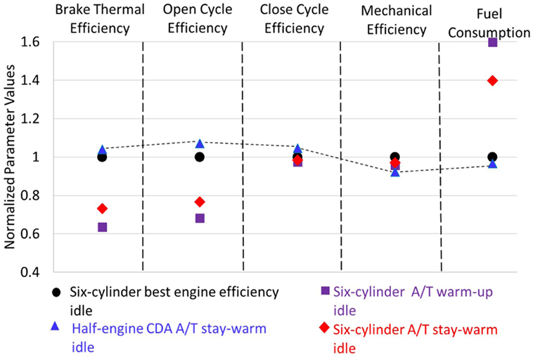
Figure 10. Experimental cycle efficiencies for the four strategies at 800 RPM/1.3 bar. The main driver for higher fuel consumption for the “Six-cylinder A/T warm-up idle” and “Six-cylinder A/T stay-warm idle” strategies is lower open cycle efficiency as a result of delayed fuel injection, and completely/mostly closed VGT positions. Fuel consumption for the “Half-engine CDA A/T stay-warm idle” strategy is lower than the “Six-cylinder best engine efficiency idle” strategy as a result of higher open cycle efficiency, which is higher due to lower pumping loss via less displaced volume during CDA.
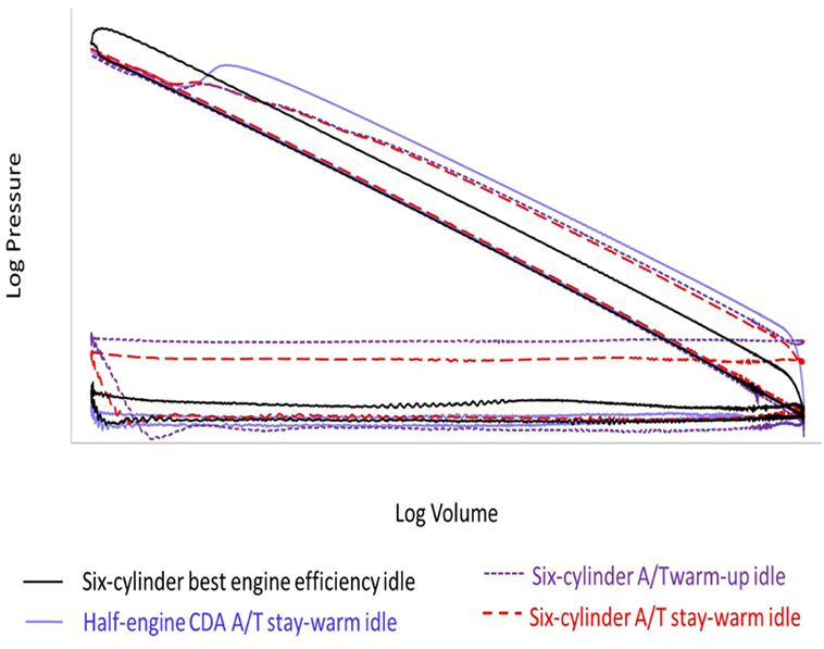
Figure 11. Experimental PV diagrams for the four strategies at 800 RPM/1.3 bar. The pumping loops are the largest for the “Six-cylinder A/T warm-up idle” and “Six-cylinder A/T stay-warm idle” strategies as a result of completely closed VGT positions and delayed SOI. The increased pumping work requires higher fuel consumption, increasing engine-outlet temperatures and flow rates for A/T warm-up. The pumping loop is smallest for the “Half-engine CDA A/T stay-warm idle” strategy as a result of lower pumping work through decreased displaced volume.
Figure 12 shows measured engine-out emissions for each of the four strategies. The EGR valve position and rail pressure were modulated such that the emissions for the “Six-cylinder A/T stay-warm idle” and “Half-engine CDA A/T stay-warm idle” strategies were comparable to that for the “Six-cylinder best efficiency idle” “Six-cylinder A/T warm-up idle” results.
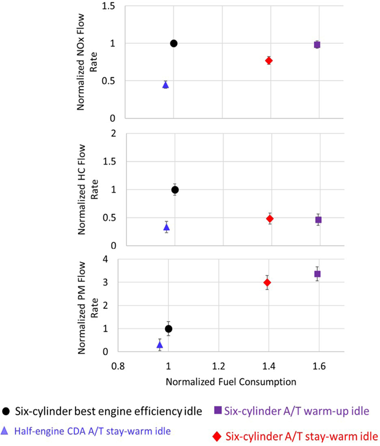
Figure 12. Experimental emissions results for each of the four strategies at 800 RPM/1.3 bar.
This section demonstrates that fuel-inefficient strategies, namely delayed SOI and completely/mostly closed VGT positions, can be used at idle to increase the engine-outlet temperature and flow rates for A/T component warm-up during conventional Six-cylinder operation. These strategies can also be used to maintain elevated A/T component temperatures, with Half-engine CDA being preferred given its lower fuel consumption, elevated temperature, and lower exhaust flow rate. The next section will demonstrate this during the HD-FTP, via drive cycle-resolved comparisons of cumulative predicted tailpipe NOx and measured fuel consumption.
6. Half Engine CDA at Sections of the HD-FTP with BMEP Below 3 Bar
In the previous section, half engine CDA was presented as a fuel-efficient strategy at loaded idle to maintain A/T component temperatures once they reach 200°C via reduced exhaust flow rate and sufficient engine-outlet temperatures to prevent A/T cooling. In order to further reduce fuel consumption over the HD-FTP drivecycle and simultaneously maintain A/T component temperatures, non-idle sections of the HD-FTP where BMEP < 3 bar were also considered for half engine CDA.
The following section includes results of implementing half engine CDA at both loaded idle sections and sections where BMEP < 3 bar over the HD-FTP test sequence.
7. Results—Fuel Economy and Tailpipe NOx Impact of Conventional and CDA-Enabled A/T Thermal Management Strategies During the HD-FTP
7.1. Results
The results from four HD-FTP experiments are compared in this section in order to demonstrate that: (i) tailpipe NOx reductions are possible via fuel-inefficient Six-cylinder A/T thermal management strategies (delayed fuel injection and maximally/mostly closed VGT position), and (ii) similar tailpipe NOx levels are possible with notably lower fuel consumption through use of Half-engine CDA during idle for A/T stay-warm operation. The four HD-FTP operating strategies include:
1. Six-cylinder best engine efficiency cycle—the result of running the engine across the HD-FTP using a stock engine calibration developed for best engine fuel economy. This strategy incorporates the “Six-cylinder best engine efficiency idle” strategy described in the previous section during idle, and provides a baseline for tailpipe emissions and fuel consumption.
2. Six-cylinder A/T thermal management cycle—the results of running the engine across the HD-FTP using an engine calibration that meets current on-highway emissions limits. This strategy incorporates delayed fuel injections at all possible operating conditions (including non-idle conditions), and maximally closed VGT position at loaded idle, in order to increase engine-outlet temperatures and flow rates. The approach uses the previously described “Six-cylinder A/T warm-up idle” and “Six-cylinder A/T stay-warm idle” strategies during idle for idle portions of the cycle where SCR outlet temperatures are below 200°C (shaded red “warm-up” idle sections in Figure 13), and above 200°C (shaded green “stay warm” idle sections in Figure 13), respectively. At non-idle conditions the late injections also reduces engine-outlet NOx, which together with faster A/T component warm-up, reduce tailpipe NOx to acceptable levels. This operating mode is included to demonstrate the fuel consumption increases typically required during conventional Six-cylinder engine operation in order to thermally manage the A/T in a way consistent with meeting current emissions limits.
3. Half-engine CDA A/T stay-warm idle cycle—results of running the “Six-cylinder A/T thermal management cycle” with one modification: using the “Half-engine CDA A/T stay-warm idle” mode instead of the “Six-cylinder A/T stay-warm idle” mode once the SCR outlet temperature is above 200°C (shaded green sections in Figure 13). This strategy demonstrates the fuel savings possible through use of CDA during idle for A/T component temperature maintenance.
4. Half-engine CDA A/T stay-warm idle/non-idle cycle—results of running the “Six-cylinder A/T thermal management cycle” with following modifications: using the “Half-engine CDA A/T stay-warm idle” at stay-warm idle (shaded green sections in Figure 13), and running “Half-engine CDA A/T stay-warm non-idle” sections where BMEP < 3 bar (shaded brown sections in Figure 13). An issue with compressor surge, which was initially observed during six-cylinder to CDA transitions (at high speed sections where BMEP < 3 bar), was resolved by appropriately delaying the transition. The “Half-engine CDA A/T stay-warm non-idle” strategy demonstrates the additional fuel savings possible through use of CDA during non-idle sections of the HD-FTP with A/T component temperature maintenance.
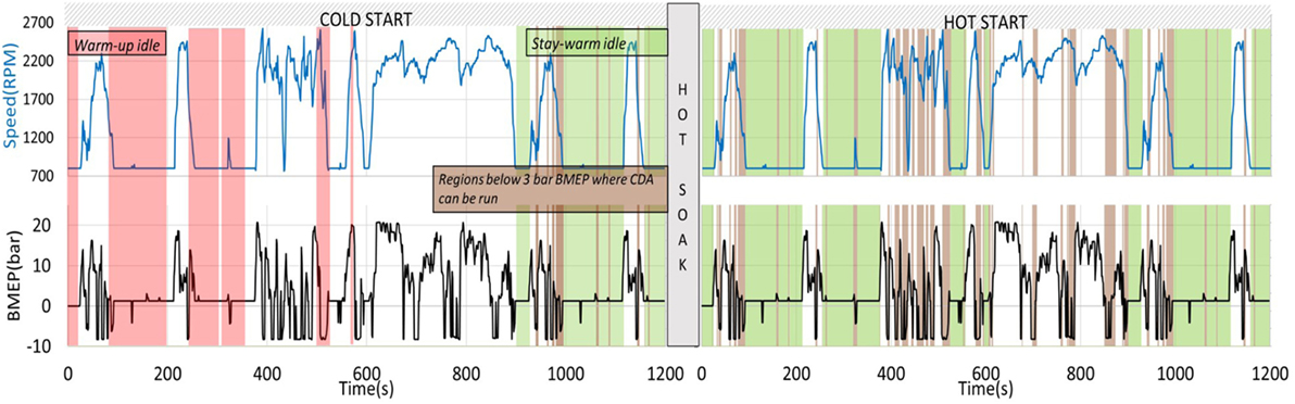
Figure 13. Test sequence for the HD-FTP cycle. Shaded red sections correspond to “A/T warm-up” idle operation. Shaded green sections correspond to “A/T stay-warm” idle operation while shaded brown sections correspond to “A/T stay-warm non-idle” where BMEP < 3 bar. For the “Six-cylinder A/T thermal management cycle,” the “Six-cylinder A/T warm-up idle” and “Six-cylinder A/T stay-warm idle” strategies are used during the warm-up and stay-warm idle sections, respectively. For the “Half-engine CDA A/T stay-warm idle cycle” the “Six-cylinder A/T warm-up idle” and “Half-engine CDA A/T stay-warm idle” strategies are used during the warm-up and stay-warm idle sections, respectively. For the “Six-cylinder best engine efficiency cycle” the “Six-cylinder best engine efficiency idle” strategy was used for both the warm-up and stay-warm, idle sections.
Figure 14 summarizes the main HD-FTP cycle results for each of these strategies. As shown, a 35% reduction in tailpipe NOx was possible via the “Six-cylinder A/T thermal management cycle” strategy, albeit at the expense of an approximate 5% increase in fuel consumption over the HD-FTP. The implementation of “Half-engine CDA A/T stay-warm idle” during idle (as part of the “Half-engine CDA A/T stay-warm idle cycle”), for conditions in which the SCR system was at least 200°C, results in very similar tailpipe NOx levels, with a 3% fuel consumption reduction compared to the “Six-cylinder A/T thermal management cycle.” In addition to implementation of “Half-engine CDA A/T stay-warm idle” during idle, “Half-engine CDA stay-warm idle/non-idle cycle” also uses Half-engine CDA at non-idle sections (BMEP < 3 bar) and the result is a further 0.4% improvement in fuel consumption over “half-engine CDA A/T stay-warm idle cycle.” The remainder of this section of the paper will describe, in detail, the reasons for these results. The fuel consumption results shown in Figure 14 were determined via experimental fuel consumption measurements on the test engine. Measured SCR outlet temperatures were used as inputs to an assumed SCR NOx conversion efficiency map (per Figure 15) to estimate the instantaneous tailpipe NOx emissions. These were then integrated to generate the results shown in Figure 14, and subsequent plots described below.
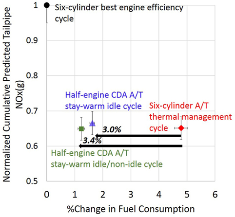
Figure 14. Up to 3.0% improvement in fuel consumption can be obtained by implementing CDA at loaded idle sections of the HD-FTP. Moreover, 3.4% improvement can be obtained by implementing CDA at appropriate non-idle sections along with loaded idle sections. The ability of CDA to maintain A/T temperature is reflected in the form of nearly equal/lower tail pipe out NOx as compared to Six-cylinder thermal management.
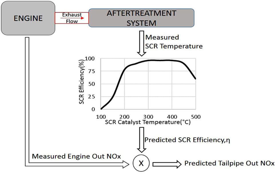
Figure 15. Measured SCR temperature from the A/T hardware is used to predict SCR efficiency. The SCR efficiency curve shows that efficiency reaches its maximum value for catalyst temperatures between 250 and 450°C. Tailpipe-out NOx is estimated using this predicted SCR efficiency.
Figures 16–18 show results from running the four aforementioned strategies over the HD-FTP. All of the results shown were experimentally measured, except for the “SCR Efficiency” and “Tailpipe Out NOx,” which were estimated using the strategy shown in Figure 15. Figure 16A shows the delayed start of injection (SOI) implemented for the “Six-cylinder A/T thermal management cycle,” “Half-engine CDA A/T stay-warm idle cycle,” and “Half-engine CDA stay-warm idle/non-idle cycle” except for during hard transients (for all of them) and during stay-warm idle for the “Half-engine CDA A/T stay-warm idle cycle” and “Half-engine CDA stay-warm idle/non-idle cycle.”
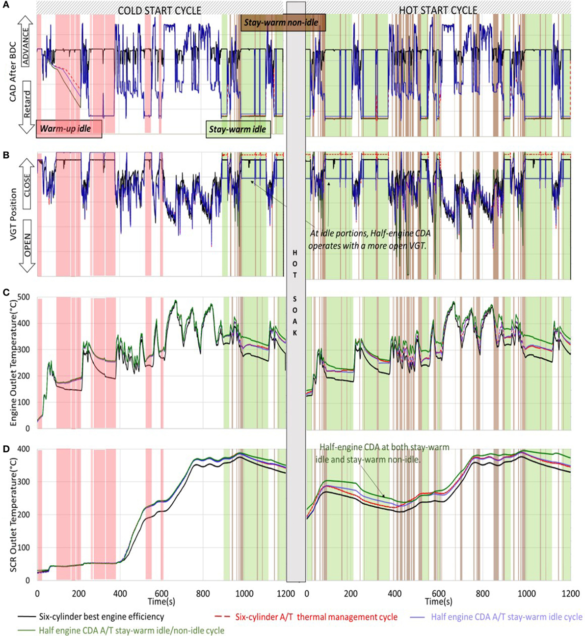
Figure 16. (A) Fuel start of injection (SOI) implemented over the HD-FTP for each of the cycles. (B) VGT positions implemented over the HD-FTP for each of the cycles. (C,D) The “Six-cylinder A/T thermal management cycle” and “Half-engine CDA A/T stay-warm idle cycle” strategies result in engine-outlet gas temperatures (C), and SCR outlet temperatures (D), that are comparable to each other, and superior to those for the “Six-cylinder best engine efficiency cycle.” “Half-engine CDA stay-warm idle/non-idle cycle” results in higher EOT and SCR outlet temperature than the other three cycles.
Figure 16B shows a maximally, or mostly, closed VGT for all idle sections of the “Six-cylinder A/T thermal management cycle,” but only during the warm-up idle sections of the “Half-engine CDA A/T stay-warm idle cycle” and “Half-engine CDA stay-warm idle/non-idle cycle.” The “Six-cylinder A/T thermal management cycle,” “Half-engine CDA A/T stay-warm idle cycle,” and “Half-engine CDA stay-warm idle/non-idle cycle” are the same during the A/T warm-up phase, as expected.
Figure 16C illustrates that the engine-outlet temperature for both the “Six-cylinder A/T thermal management cycle” and the “Half-engine CDA A/T stay-warm cycle” are higher than the “Six-cylinder best engine efficiency cycle,” as expected. Even higher engine-outlet temperatures are seen for “half-engine CDA A/T stay-warm idle/non-idle cycle” due to additional Half-engine CDA operation during stay-warm non-idle sections (BMEP < 3 bar). The elevated temperatures, and favorable exhaust flow rates (not shown), result in higher SCR outlet temperatures throughout the entire cycle, as shown in Figure 16D.
Figure 17 demonstrates that the SCR NOx conversion efficiency for “Half-engine CDA stay-warm idle/non-idle cycle” is higher than the other cycles, while conversion efficiencies for the “Half-engine CDA A/T stay-warm idle cycle” and the “Six-cylinder A/T thermal management cycle” are comparable to each other, and are higher than those for the “Six-cylinder best engine efficiency cycle.” This is a direct result of higher SCR outlet temperatures for these cycles (per Figure 16D). The higher engine-out NOx (via earlier SOI), and lower SCR efficiency, for the “Six-cylinder best engine efficiency cycle” result in higher predicted tailpipe-out NOx compared to the two thermal management cycles (per Figure 17). The cold and hot start cycle NOx results are summed (with proper weighting), and compared, to yield the NOx differences illustrated in Figure 14.
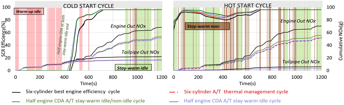
Figure 17. The improved SCR outlet temperatures for the “Six-cylinder A/T thermal management cycle,” “Half-engine CDA A/T stay-warm idle cycle,” and “Half-engine CDA stay-warm idle/non-idle cycle” result in greater SCR efficiencies relative to the “Six-cylinder best engine efficiency cycle.” The early fuel injections used during the “Six-cylinder best engine efficiency cycle” lead to increased engine-outlet NOx rates for that cycle. The aforementioned SCR efficiency and engine-out NOx responses result in cumulative tailpipe-out NOx levels for the “Six-cylinder A/T thermal management cycle” and “Half-engine CDA A/T stay-warm idle cycle” that are similar and notably lower than those for the “6 cylinder best engine efficiency cycle.” Relative to the other cycles, “Half-engine CDA A/T stay warm idle/non-idle cycle” has higher SCR efficiencies which result in a reduction in tail pipe out NOx.
Figure 18A shows the cumulative difference in fuel consumption between the “Six-cylinder A/T thermal management cycle” and the “Six-cylinder best engine efficiency cycle.” The implementation of delayed SOI and maximally/mostly closed VGT positions during the “Six-cylinder A/T thermal management cycle” results in a higher fuel consumption during the vast majority of the cycle, which is consistent with the steady increase in the fuel consumption difference shown. Figure 18B shows the cumulative difference in the fuel consumption between the “Six-cylinder A/T thermal management cycle” and the “Half-engine CDA A/T stay-warm idle cycle.” The only difference between these cycles is the use of the “Half-engine CDA A/T stay-warm idle” mode during the stay-warm idle sections of the HD-FTP, resulting in fuel consumption differences during only the stay-warm idle sections. Figure 18C shows the difference in fuel consumption between the “Half-engine CDA stay-warm idle/non-idle cycle” and the “Six-cylinder A/T thermal management cycle.” The differences are seen to arise from both loaded idle sections (due to use of “Half-engine CDA A/T stay-warm idle” mode) and non-idle sections (due to use of “Half-engine CDA A/T stay warm non-idle” mode at non-idle sections where BMEP < 3 bar). The difference in fuel consumption is seen to be relatively constant at other portions of the test. The fueling differences in Figure 14 result for the weighted summation of the cold and hot starts for each of the strategies.
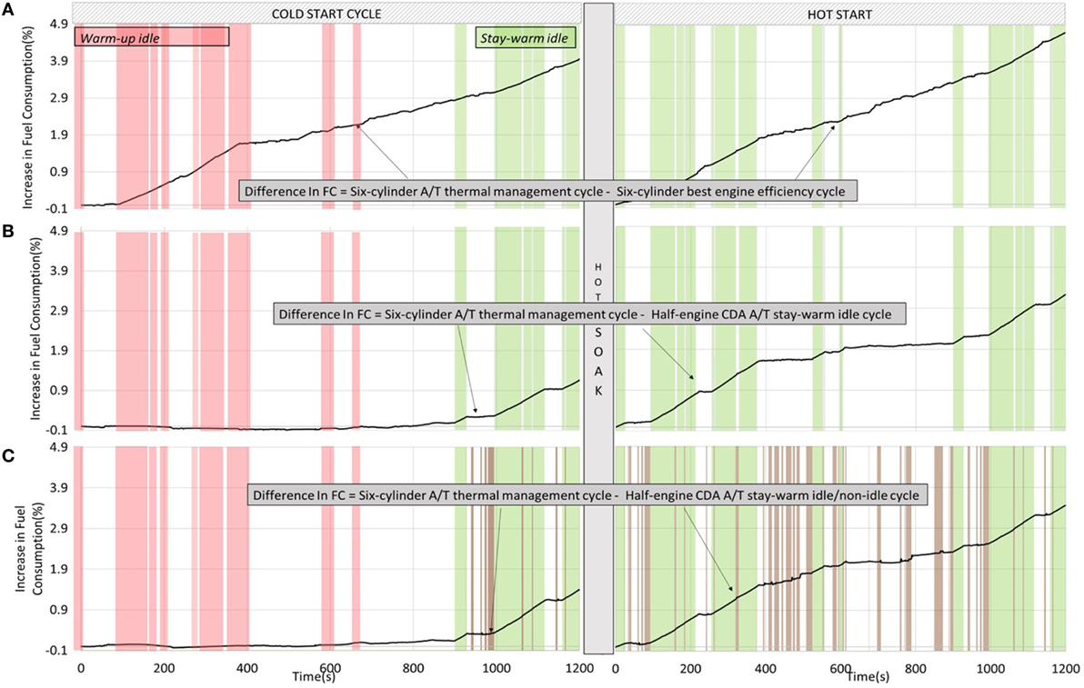
Figure 18. (A) Delayed fuel injections and maximally/mostly closed VGT positions results in higher fuel consumption for the “Six-cylinder A/T thermal management cycle” compared to the “Six-cylinder best engine efficiency cycle.” (B) The more efficient Half-engine CDA operation during the stay-warm idle sections of the “Half-engine CDA A/T stay-warm idle cycle” result in fuel consumption reductions during those periods relative to the fuel consumption during the “Six-cylinder A/T thermal management cycle.” (C) “Half-engine CDA stay-warm idle/non-idle cycle” can be seen to have lower fuel consumption than “Six-cylinder A/T thermal management cycle” during both idle and non-idle sections.
7.2. Torque Response of CDA and Drive Cycle Validity
Figure 19 demonstrates that implementing Half-engine CDA during idle still allowed a normal torque response of the engine, a concern that has been previously raised regarding the dynamic performance of CDA. The validity of the torque response is also confirmed by performing a regression analysis on the drive cycle speed and torque data. The reference torque and measured drive cycle torque are compared to obtain values a set of statistical parameters by performing a regression analysis. Acceptable values of these parameters for a valid drive cycle along with the obtained values of these parameters for the CDA drive cycle are shown in Table 2.

Figure 19. The torque responses during the “Six-cylinder A/T thermal management cycle” and the “Half-engine CDA A/T stay-warm idle cycle” are essentially the same, demonstrating the torque response is not compromised as the engine transitions into, and out, of Half-engine CDA operation at idle and non-idle.
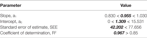
Table 2. EPA specified Statistical Criteria for drive cycle torque.
8. Conclusion
This paper demonstrates that CDA can be used to maintain aftertreatment temperatures in a more fuel-efficient manner through reductions in airflow and pumping work. The incorporation of CDA to maintain desired aftertreatment temperatures during the idle conditions and appropriate non-idle conditions (<3 bar BMEP) of the HD-FTP was experimentally demonstrated to result in fuel savings of 3.4% over the HD-FTP drivecycle. Additional findings include:
1. Significant HD-FTP tailpipe NOx reductions (approximately 35%) are possible via aftertreatment thermal management strategies including delayed start of injection (SOI) and maximally closed VGT positions, albeit with increased fuel consumption (approximately 5%).
2. Approximately 80% of those fuel consumption increases can be eliminated (corresponding to a 3.4% decrease in fuel consumption) by using half engine CDA at loaded idle as a means to more efficiently maintain desired aftertreatment component temperatures.
8.1. Future Work
1. Investigate additional regions in the drivecycle where CDA can be implemented with different number of firing cylinders.
2. Optimize CDA at loaded idle to further improve thermal performance.
Author Contributions
Leaders of the effort include GS, JM, LF, MJ, DG, and CA. Essential experimental efforts from MJ, DG, CA, MV, KV, and AT. Essential hardware and software support from EK and DS.
Conflict of Interest Statement
The authors declare that the research was conducted in the absence of any commercial or financial relationships that could be construed as a potential conflict of interest.
Acknowledgments
This project is funded by Cummins Inc. and Eaton, with experiments performed at Ray W. Herrick Laboratories at Purdue University. The experimental engine was provided by Cummins Inc. and technical assistance was provided by both Cummins Inc. and Eaton. The authors would also like to thank their colleagues Aswin Ramesh and Troy Odstrcil, and the shop staff at Herrick labs, particularly David Meyer and Ron Evans for the support they have extended toward this work.
Funding
Cummins and Eaton funded this effort.
Abbreviations
BTE, brake thermal efficiency; CAC, charge air cooler; CCE, closed cycle efficiency; CDA, cylinder deactivation; DOC, diesel oxidation catalyst; DPF, diesel particulate filter; ECM, engine control module; EGR, exhaust gas recirculation; EOT, engine outlet temperature; EPA, environmental protection agency; FTP, federal testing procedure; GSI, generic serial interface; LFE, laminar flow element; LVDT, linear variable differential transformer; ME, mechanical efficiency; NOx, oxides of nitrogen; OCE, open cycle efficiency; PM, particulate matter; SCR, selective catalytic reduction; TOT, turbine-outlet temperature; UHC, unburnt hydrocarbons; VGT, variable geometry turbine; VVA, variable valve actuation.
References
Blakeman, P., Chiffey, A., Phillips, P., Twigg, M., and Walker, A. (2003). Developments in diesel emission aftertreatment technology. SAE Technical Paper 2003-01-3753. doi: 10.4271/2003-01-3753
Charlton, S., Dollmeyer, T., and Grana, T. (2010). Meeting the US heavy-duty EPA 2010 standards and providing increased value for the customer. SAE Int. J. Commer. Veh. 3, 101–110. doi:10.4271/2010-01-1934
Ding, C., Roberts, L., Fain, D. J., Ramesh, A. K., Shaver, G. M., McCarthy, J., et al. (2015). Fuel efficient exhaust thermal management for compression ignition engines during idle via cylinder deactivation and flexible valve actuation. Int. J. Engine Res. 17, 619–630. doi:10.1177/1468087415597413
Falkowski, A., McElwee, M., and Bonne, M. (2004). “Design and development of the daimlerchrysler 5.7l hemi® engine multi-displacement cylinder deactivation system,” in SAE Technical Paper 2004-01-2106. doi:10.4271/2004-01-2106
Gehrke, S., Kovács, D., Eilts, P., Rempel, A., and Eckert, P. (2013). Investigation of VVA-based exhaust management strategies by means of a HD single cylinder research engine and rapid prototyping systems. SAE Int. J. Commer. Veh. 6, 47–61. doi:10.4271/2013-01-0587
Hou, X., Ma, Y., Peng, F., Yan, F., and Zhang, X. (2010). “Research on temperature characteristics of dpf regeneration technology based on catalytic combustion of fuel injection,” in 2010 Asia-Pacific Power and Energy Engineering Conference (APPEEC) (IEEE), 1–4.
Koebel, M., Elsener, M., and Kleemann, M. (2000). Urea-SCR: a promising technique to reduce NOx emissions from automotive diesel engines. Catal. Today 59, 335–345. doi:10.1016/S0920-5861(00)00299-6
Leone, T. G., and Pozar, M. (2001). Fuel economy benefit of cylinder deactivation-sensitivity to vehicle application and operating constraints. SAE Technical Paper Series 1645, 10–11. doi:10.4271/2001-01-3591
Lu, X., Ding, C., Ramesh, A., Shaver, G., Holloway, E., McCarthy, J., et al. (2015). Impact of cylinder deactivation on active diesel particulate filter regeneration at highway cruise conditions. Front. Mech. Eng. 1:9. doi:10.3389/fmech.2015.00009
Maiwald, O., Brück, R., Rohrer, S., Zaki, M., Schatz, A., and Atzler, F. (2010). “Optimised diesel combustion and SCR exhaust aftertreatment combined with a 48 v system for lowest emissions and fuel consumption in RDE,” in 25th Aachen Cooloquium Automobile and Engine Technology. Available at: http://www.emitec.com/fileadmin/user_upload/Presse/Paper_Vortraege/2016_Aachen_Conti_Super_Clean_Diesel_V10.pdf
McCarthy, J. Jr. (2016). “Cylinder deactivation for optimizing conventional engines,” in Driving Automotive Innovation Conference, Washington, D.C. Available at: http://www.theicct.org/events/driving-automotive-innovation
Ramesh, A., Shaver, G., Allen, C., Gosala, D., Nayyar, S., Caicedo, D., et al. (2017). Utilizing low airflow strategies, including cylinder deactivation, to improve fuel efficiency and aftertreatment thermal management. Int. J. Engine Res. 1, 1. doi:10.1177/1468087417695897
Song, X., Surenahalli, H., Naber, J., Parker, G., and Johnson, J. H. (2007). Experimental and modeling study of a diesel oxidation catalyst (DOC) under transient and CPF active regeneration conditions. SAE Technical Paper 2013-01-1046, 10–11. doi:10.4271/2013-01-1046
Stadlbauer, S., Waschl, H., Schilling, A., and del Re, L. (2013). “DOC temperature control for low temperature operating ranges with post and main injection actuation,” in Technical Report, SAE Technical Paper.
Stanton, D., Charlton, S., and Vajapeyazula, P. (2013). Diesel engine technologies enabling powertrain optimization to meet U.S. greenhouse gas emissions. SAE Int. J. Engines 6, 1757–1770. doi:10.4271/2013-24-0094
Stanton, D. W. (2013). Systematic development of highly efficient and clean engines to meet future commercial vehicle greenhouse gas regulations. Diesel Engine 2013, 5–16. doi:10.4271/2013-01-2421
United States Environmental Protection Agency. (2010). Heavy-Duty Highway Compression-Ignition Engines and Urban Buses: Exhaust Emission Standards. Available at: https://nepis.epa.gov/Exe/ZyPDF.cgi?Dockey=P100O9ZZ.pdf
United States Environmental Protection Agency. (2015). Electronic Code of Federal Regulations, CFR 2015 Title 40 Vol 33 Sec 1065.530. Available at: http://www.ecfr.gov/cgi-bin/retrieveECFR?gp=1&SID=accec04b7513dfe3776d4914791e0042&ty=HTML&h=L&mc=true&r=PART&n=pt40.33.1065#se40.37.1065_1320
Keywords: cylinder deactivation, HD-FTP, fuel economy, thermal management, diesel engine
Citation: Joshi MC, Gosala DB, Allen CM, Vos K, Van Voorhis M, Taylor A, Shaver GM, McCarthy J, Jr. Stretch D, Koeberlein E and Farrell L (2017) Reducing Diesel Engine Drive Cycle Fuel Consumption through Use of Cylinder Deactivation to Maintain Aftertreatment Component Temperature during Idle and Low Load Operating Conditions. Front. Mech. Eng. 3:8. doi: 10.3389/fmech.2017.00008
Received: 18 May 2017; Accepted: 05 July 2017;
Published: 08 August 2017
Edited by:
Stephen Anthony Ciatti, Argonne National Laboratory (DOE), United StatesReviewed by:
Georgios Mavropoulos, National Technical University of Athens, GreeceKhizer Tufail, Ford Motor Company, United Kingdom
Copyright: © 2017 Joshi, Gosala, Allen, Vos, Van Voorhis, Taylor, Shaver, McCarthy, Stretch, Koeberlein and Farrell. This is an open-access article distributed under the terms of the Creative Commons Attribution License (CC BY). The use, distribution or reproduction in other forums is permitted, provided the original author(s) or licensor are credited and that the original publication in this journal is cited, in accordance with accepted academic practice. No use, distribution or reproduction is permitted which does not comply with these terms.
*Correspondence: Gregory M. Shaver, gshaver@purdue.edu