Improving the Efficiency of a Thermionic Energy Converter Using Dual Electric Fields and Electron Beaming
 Ian Bickerton1
  Neil A. Fox1,2*
- 1School of Chemistry, University of Bristol, Bristol, United Kingdom
- 2HH Wills Physics Laboratory, School of Physics, University of Bristol, Bristol, United Kingdom
Experiments have been conducted on a dual electric grid thermionic device to investigate an alternative method of space charge mitigation in a thermionic energy convertor (TEC). Two electric grids, the attractor and deflector grids, provide opposing electric fields to overcome space charge while minimizing power losses to the attractor grid. Electron beams are formed in the electrode gap providing a more efficient electron transport from hot cathode to collector. The attractor gird can be run in DC or pulse mode which usefully supports transformer coupling for the energy convertor output. This is a simple low cost inter-electrode space charge solution running at low voltage which has the potential to improve TEC efficiency, increase reliability, and reduce the cost of manufacture.
Introduction
A thermionic energy converter (TEC) is a device that harvests electrical power from heat and unlike thermoelectric converters requires a vacuum or low-pressure gas ambient to operate efficiently. In contrast to thermoelectric devices, TECs are normally operated at elevated temperatures well above red heat to realize large thermionic emission currents and can be considered as a heat engine whereby a large temperature difference between the cathode and cooled anode collector is required for optimum efficiency (Rasor, 1963).
Thermionic energy convertor technology was intensively studied in the 1950s and 1960s as a potential solar technology and for harvesting heat from nuclear reactors for both civil and military power generation. Although there were significant advances in the design and methods for realizing TECs exhibiting efficiencies exceeding 15% (Hatsopoulos and Kaye, 1958), there were technical issues not satisfactorily resolved in the scale up, such as cathode stability, maintaining close electrode spacing, collector reflection losses, and magnetic field generation (Schock, 1960). Consequently, the continuation of TEC device development occurred only for use in space exploration where the device complexity and high unit cost could be offset by the savings in payload costs for compact kilowatt electrical power generation (Ponomarey-Stepnoi et al., 1995).
During operation, the TEC has a positively charged emitter and a negatively charged collector. Electrons leaving the hot emitter create space charge and this limits the current flow from emitter to collector in accord with the Child–Langmuir Law. This space charge is formed by a significant fraction of the thermionic electrons that possess insufficient kinetic energy to transit the vacuum gap to reach the collector. These electrons are subsequently attracted back toward the emitter where they become part of a cloud of electrons forming a virtual cathode in front of the emitter, greatly suppressing emission and device efficiency.
The established approaches to space charge mitigation include neutralization using an easily ionizable gas, such as cesium, introduced into the vacuum space (Hernqvist, 1963) or suppression whereby the inter-electrode vacuum space is made very small, typically the optimal separation is defined by the wavelength of thermal radiation of the hot emitter (~0.9–10 µm) (Lee et al., 2012).
A combination of magnetic and electrical fields has also been used to successfully mitigate space in thermionic devices. The earliest configuration, the magnetic TEC (Hatsopoulos and Gyftopoulos, 1973) was a three-electrode arrangement with an emitter and collector disposed on the same plane with a grid electrode directly above, producing a perpendicular electric field, which in combination with a longitudinal magnetic field produced electron transport from a hot emitter to collector on a circular path. Electron diffraction, scattering, and device instabilities confined this design to prototype testing.
The more recent work from Max Planck Institute for solid state research (Moyzhes and Geballe, 2005; Meir et al., 2013) have proposed an inter-electrode grid or annular ring to produce an electric field and makes use of a perpendicular magnetic field to attain helical or focused electron paths to reduce current loss to the grid electrode. The Max Planck group have also proposed an inter-electrode grid configuration that eliminates the need for a magnetic (Wanke et al., 2016), while researchers at the University of California at Berkeley (Regan et al., 2012) have looked at the electrical polarization of a thin film collector and/or structured collectors for the implementation of novel field-effect PV devices which could be applied to TEC designs. The principle objective of all these designs is to transport electrons with minimal power loss, the electrical designs share a common approach namely, use of an accelerating electric field which can be coupled with a magnetic field to inhibit current or power loss to any additional electrodes.
In this report, we describe another approach to space charge mitigation which is realized by inserting two aligned metal grid electrodes in the vacuum space between the emitter and collector. The grid closest to the emitter we have named the deflector grid with a small negative bias voltage. The second grid, the attractor, is positioned nearer the collector and is biased with a positive voltage, larger in magnitude than the deflector bias but sufficient to accelerate thermionic carriers through the first grid toward the collector. By modulating the deflector grid voltage, it has been demonstrated that the loss to the attractor grid can be minimized by deflecting electrons to the collector.
Materials and Methods
The goal of this work was to investigate a different approach to thermionic space charge mitigation using a dual electric field and removing the need for a magnetic field while attaining efficient electron transport with minimal power loss. Working from first principles, it is possible to use multiple electric grids and low-voltage signals to control electron transport from emitter to collector. In the basic configuration of Figure 1, a deflector grid in close proximity to the cathode, and working in conjunction with a geometrically aligned attractor grid, can provide efficient TEC operation.
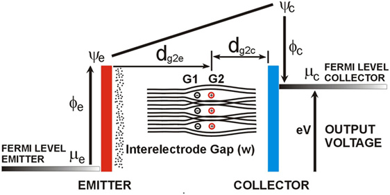
Figure 1. Concept diagram of the dual-grid thermionic energy convertor, grid 2 (G2) is the attractor and grid 1 (G1) is the deflector, the grids work in conjunction to attain electron transport and space charge mitigation with minimal power loss to G2, the device geometry and voltages/signals are important to attain efficient operation.
The experimental setup consisted of a vacuum-processed, dual-grid TEC assembly of Figure 3 using commercially wound grids, a dual laboratory DC voltage power supply to provide negative bias to the deflector grid, a 1 GHz signal generator which provided a range of positive DC to square wave pulse frequencies to the attractor grid, For TEC tests, the collector (anode) was connected through a load resistor to the emitter, output current and voltage were monitored.
The dual-grid TEC assembly was fitted with two indirectly heated thermionic cathodes. The thermionic emitter was composed of a nickel shell with a proprietary barium and strontium oxide-coated cathode running at a temperature of 850–900°C.
The deflector and attractor grids were commercial nickel wire windings of a cylindrical TEC assembly shown in Figure 3 were configured so that the attractor grid was geometrically aligned to the deflector grid. When a short positive voltage pulse is applied to the attractor grid, with the deflector grid held at a small negative bias voltage, the thermionic electrons were constrained to follow a narrow range of trajectories while transiting the two grids and be collected by the anode, this results in a reduced current or power loss to the attractor grid.
This dual-grid TEC configuration offers a simple and effective method to mitigate space charge losses with the potential to improve device efficiency and facilitate pulse mode or AC TEC operation.
Results
In laboratory testing, the focus was on establishing a TEC voltage using a simple static electric field, with the large inter-electrode device geometry and commercial BaO/Sr cathode, this was approximately 0.5 V. The signal applied to the attractor grid (G2 of Figure 1) to attain TEC operation was 1 V, and the approach was to use low-voltage signals to allow TTL drivers in the pulse mode experiments. The power loss to grid 2, with the deflector grid (G1) non-operational, was approximately 300 µW as shown in Figure 2. A small negative voltage applied to the deflector grid (G1 of Figure 1) reduces the current flow or coupling into grid 2 by deflection and electron momentum. Figure 2 shows that the power loss to the attractor grid 2 can be substantially reduced (300–50 µW) while maintaining TEC output voltage/power. A simple theoretical analysis points to the TEC current in this device being closely related to the Child–Langmuir Law or three-halves-power law due to the superposition of the dual-grid electric fields. Optimal performance in DC mode on this device at these low voltages was at a deflector grid voltage of −0.4 V; however, the two grids work in conjunction and other optimal working points are available at higher voltages.
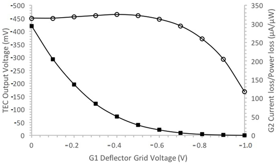
Figure 2. Results of the dual-grid Mk I thermionic energy convertor (TEC), measurement error 2% (open circles) TEC output voltage (mV) (filled squares) grid 2, current loss/power loss (μA/μW)—grid 2 is driven at 1 V therefore power and current losses are numerically equal. TEC output voltage is established with the grid 2 field, and power losses minimized using the grid 1 to inhibit current to grid 2.
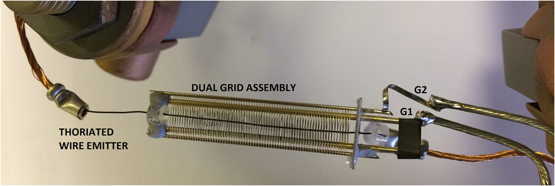
Figure 3. Photograph of the Mk II dual-grid thermionic energy convertor assembly illustrating the cylindrical construction of the commercial grids in a vacuum demountable device, inter-electrode distance approximately 1 cm, thoriated wire emitter, and nickel collector.
Figure 2 provides the electrical performance of the dual-grid device; minimal power is lost to the pulsed grid and an alternating current TEC gives opportunities to transform the output voltage. Note, the deflector grid does not draw power since it is at a negative potential; however, induction loss is a possibility in any device with electron transport. With the device geometry used in this design, no significant induction losses to grid 1 or 2 were evident. Operating grid voltages of this device would also be influenced by the grid and collector metals used in the fabrication due to electrochemical potentials.
Some investigation of TEC pulse mode operation was possible with this test device, at a frequency of 10 kHz at which some enhancement of the TEC output can be attained. These pulse mode experiments demonstrated the time constant of the TEC under test, and this enabled us to obtain a DC output at approximately 250 kHz with the TEC device essentially acting as an inductor. This arrangement can be thought of as an oscillator tuned to the transit time of electrons. Increasing the attractor grid to higher frequencies we could maintain or increase TEC output power while attaining a further 80% reduction in power losses to the grids, this was significant and requires further investigation with the Mk III planar device.
Discussion
The experimental work reported demonstrates the use of a dual electrostatic grid TEC design which offers a solution to space charge and has the potential to enhance conversion efficiency. Electrical fields working in conjunction in this simple approach gives an alternative to close spaced TEC designs where reliability can be a problem. Further work is planned to fully investigate the pulse mode or AC operation to improve TEC power output and efficiency. This work is outside the scope of the current project and is best achieved with an Mk III planar TEC design with increased power output using a commercial dispenser cathode and dual grids with a greater precision on the positional control of the grids relative to the emitter and collector.
Author Contributions
IB and NF contributed equally to the preparation of the manuscript. IB performed the experimental work and data elaboration.
Conflict of Interest Statement
The authors declare that the research was conducted in the absence of any commercial or financial relationships that could be construed as a potential conflict of interest.
Acknowledgments
We thank project team members Mr. Alex Croot, Dr. Hugo Andrade, and Prof. Martin Cryan for fruitful discussions about the multi-grid TEC concept. We also thank Mr. John Rowden for his assistance with the fabrication of dual-grid structures. We also thank Miss. Alice Bickerton for her help preparing the diagram and figure.
Funding
This work was supported by the Engineering and Physical Sciences Research Council under grant no. EP/K030302/1/46623.
References
Hatsopoulos, G. N., and Gyftopoulos, E. P. (1973). Thermionic Energy Conversion, Vol. 1. Cambridge, MA: MIT Press.
Hatsopoulos, G. N., and Kaye, J. (1958). Measured thermal efficiencies of a diode configuration of a thermo electron engine. J. Appl. Phys. 29, 1124–1125. doi: 10.1063/1.1723373
Hernqvist, K. G. (1963). Analysis of the arc mode operation of the cesium vapor thermionic energy converter. Proc. IEEE 51, 748–754. doi:10.1109/PROC.1963.2267
Lee, J.-H., Bargatin, I., Melosh, N. A., and Howe, R. T. (2012). Optimal emitter-collector gap for thermionic energy converters. Appl. Phys. Lett. 100, 173904. doi:10.1063/1.4707379
Meir, S., Stephanos, C., Geballe, T. H., and Mannhart, J. (2013). Highly-efficient thermoelectronic conversion of solar energy and heat into electric power. J. Renew. Sustain. Energy 5, 043127. doi:10.1063/1.4817730
Moyzhes, B. Y., and Geballe, T. H. (2005). The thermionic energy converter as a topping cycle for more efficient heat engines—new triode designs with a longitudinal magnetic field. J. Phys. D Appl. Phys. 38, 782–786. doi:10.1088/0022-3727/38/5/017
Ponomarey-Stepnoi, N. N., Usov, V. A., Nikolaev, Y. V., Yeriemin, S. A., Zhabotinski, Y. Y., Galkin, A. Y., et al. (1995). Conceptual design of the bimodal nuclear power system based on the “Romashka” type reactor with thermionic energy conversion system. AIP Conf. Proc. 324, 871. doi:10.1063/1.47126
Rasor, N. S. (1963). Emission physics of the thermionic converter. Proc. IEEE 51, 733–747. doi:10.1109/PROC.1963.2266
Regan, W., Byrnes, S., Gannett, W., Ergen, O., Vazquez-Mena, O., Wang, F., et al. (2012). Screening-engineered field-effect solar cells. Nano Lett. 12, 4300–4304. doi:10.1021/nl3020022
Schock, A. (1960). Effect of magnetic fields on thermionic power generators. J. Appl. Phys. 31, 1978. doi:10.1063/1.1735483
Keywords: thermionic energy converter, vacuum, electron transport, space charge mitigation, dual electric grid
Citation: Bickerton I and Fox NA (2017) Improving the Efficiency of a Thermionic Energy Converter Using Dual Electric Fields and Electron Beaming. Front. Mech. Eng. 3:14. doi: 10.3389/fmech.2017.00014
Received: 31 July 2017; Accepted: 20 October 2017;
Published: 02 November 2017
Edited by:
David B. Go, University of Notre Dame, United StatesReviewed by:
Liang Chen, Xi’an Jiaotong University, ChinaRobin Wanke, Max Planck Institute for Solid State Research (MPG), Germany
Copyright: © 2017 Bickerton and Fox. This is an open-access article distributed under the terms of the Creative Commons Attribution License (CC BY). The use, distribution or reproduction in other forums is permitted, provided the original author(s) or licensor are credited and that the original publication in this journal is cited, in accordance with accepted academic practice. No use, distribution or reproduction is permitted which does not comply with these terms.
*Correspondence: Neil A. Fox, neil.fox@bristol.ac.uk