Simulating anomalous dispersion in porous media using the unstructured lattice Boltzmann method
 Marek K. Misztal1*
  Anier Hernandez-Garcia1
  Rastin Matin1
  Dirk Müter2
  Diwaker Jha2
  Henning O. Sørensen2 Joachim Mathiesen1
- 1Biocomplexity, Niels Bohr Institute, University of Copenhagen, Copenhagen, Denmark
- 2Department of Chemistry, Nano-Science Center, University of Copenhagen, Copenhagen, Denmark
Flow in porous media is a significant challenge to many computational fluid dynamics methods because of the complex boundaries separating pore fluid and host medium. However, the rapid development of the lattice Boltzmann methods and experimental imaging techniques now allow us to efficiently and robustly simulate flows in the pore space of porous rocks. Here we study the flow and dispersion in the pore space of limestone samples using the unstructured, characteristic based off-lattice Boltzmann method. We use the method to investigate the anomalous dispersion of particles in the pore space. We further show that the complex pore network limits the effectivity by which pollutants in the pore space can be removed by continuous flushing. In the smallest pores, diffusive transport dominates over advective transport and therefore cycles of flushing and no flushing, respectively, might be a more efficient strategy for pollutant removal.
1. Introduction
Recent numerical simulations of flow in porous media in both two and three dimensions have revealed highly non-trivial flow patterns. Particles passively advected by the flow in the pore-space, so-called Lagrangian particles, follow trajectories with periods of almost stagnation punctuated by bursts of fast fluctuating motion [1–3]. In a Berea sandstone sample, it was shown by a three dimensional simulation that this intermittent behavior was equally significant in both longitudinal (the mean flow direction) and transverse directions [3]. The chaotic Lagrangian dynamic emerges despite the fact that the inertia of the fluid is negligible in many natural and industrial settings, i.e., the flow happens at low Reynolds numbers. Nonetheless, the flow might exhibit a complicated spatio-temporal behavior owing to the high heterogeneity of the pore space. The heterogeneity in fact gives rise to anomalous (non-Fickian) transport properties similar to those typically associated to high Reynolds number flow [4]. The anomalous transport has implications for the local dispersion of particles in a porous medium. It can alter the reaction rates of transported reactants or accelerate the small scale dispersion of pollutants.
In addition to the strong intermittent behavior, it has been found in both two and three dimensional simulations that the velocity autocorrelation, as a function of space, is short ranged while as a function of time the longitudinal velocity exhibits long time correlations. In the three dimensions, it was found [3] that the transverse velocity autocorrelation decays faster, though the absolute value is strongly correlated in time, a feature also observed in turbulent flows [5]. These remarkable properties have led to the suggestion that the Lagrangian particle velocities is given by a Markov process in space (at equidistant positions along the Lagrangian trajectories) and not in time [6, 7]. In a Markov process the particle motion can be seen as a correlated continuous time random walk (CTRW). Using a correlated CTRW, several signatures of anomalous transport behavior were accurately reproduced such as the long tails of the first passage time distribution [6], the non-linear scaling of the second centered moment of the particles longitudinal and transverse displacements [3, 6, 8], the probability distribution function of the Lagrangian velocity increments for different time lags among others [1].
Interesting results were also obtained in the study of scalar mixing in two dimensional porous media with different structural disorder [9]. Numerical simulations showed that the scalar concentration forms, at advanced time, a fractal-like structure composed of stripes of high concentration and with high lacunarity. The probability distribution function of the pair separation of advecting particles was fitted to a log-normal distribution and the averaged squared separation was found to grow with time as a power law whose exponent depends on the geometry. For weak and strong heterogeneities of the porous sample the exponents were found to be 1.8 and 2.8, respectively. Remarkably, we can see that the second exponent is very close to the Richardson dispersion law, characteristic of the separation of particles whose distance lie in the inertial range interval in turbulent flows. The authors proposed a stochastic model based on ad hoc arguments to describe the behavior of the pair separation of advecting particles l(t), which reflects the multiplicative nature of the stretching processes and accounts for the observed short range temporal correlations of the Lagrangian stretching rates.
Here we formulate a version of the lattice Boltzmann method on unstructured grids to efficiently simulate flow in complex pore geometries. We use the method to assess the Lagrangian dynamics of flows in the pore space of limestone samples computed by x-ray tomography. In order to faithfully compute the broadly distributed fluid velocities, it is required to represent the pore boundaries with a high resolution. Compared to classical lattice Boltzmann methods on regular grids, the unstructured grids offer a superior resolution and adaptivity [10]. We further analyze the impact of the complex pore geometry on pollutant removal from the pore space.
2. Materials and Methods
2.1. Porous Rock Samples
We have performed our pollutant dispersion studies on two different, natural porous samples, discretized using tetrahedral elements (the properties of the tetrahedral meshes are presented in Table 1).
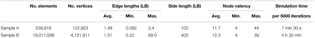
Table 1. Properties of the tetrahedral meshes used in the simulations and the wall-clock time spent per 5000 iterations of the unstructured lattice Boltzmann simulation (Intel® Xeon® 2.6 GHz).
Sample A (Figure 1) is chalk from off-shore drilling in the North Sea region (Hod chalk #15). Sample B (Figure 2) came from an outcrop of bryozoan chalk in Rødvig, Denmark. The digital 3D images were obtained by x-ray nanotomography [11] measured at beamline ID22 at the European Synchrotron Radiation Facility, France. The reconstructed volume of Sample A had a voxel size of 25 nm and an optical resolution about 150 nm. Details about the data collection and reconstruction can be found in Müter et al. [12]. The reconstructed images were corrected for ring artifacts [13] before segmentation by a dual filtering and Otsu thresholding procedure [14]. For the LBM calculations we used a subvolume of 1003 voxels, which gives a side length of 2.5 microns. Sample B was reconstructed and segmented in the same way as Sample A. The only difference is that it was reconstructed with a voxel size of 50 nm leading to an optical resolution of about 300 nm. The LBM calculations were performed on a subvolume of 4003 voxels (side length of 20 microns). In Sample A, the diameter of the pore throats corresponds to at least 6 voxel sizes, while the typical pore diameter is 30–40 voxels. In Sample B, the smallest pore throats are about 5 voxels, however, the flow is dominated by a large, well connected pore system, where the pore diameter is 50 voxels and above.
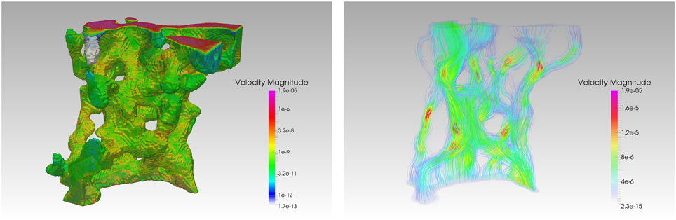
Figure 1. Left: The surface plot of the investigated volume of Sample A, colored according to the surface velocities. The values on the solid boundary are at least three orders of magnitude lower than the values on the outlet (top surface of the mesh). Right: The streamlines of the steady-state velocity field, generated for τ = 0.02, Δρ = 2.5 · 10−6. Both images were generated using ParaView 4.3.1. [32].
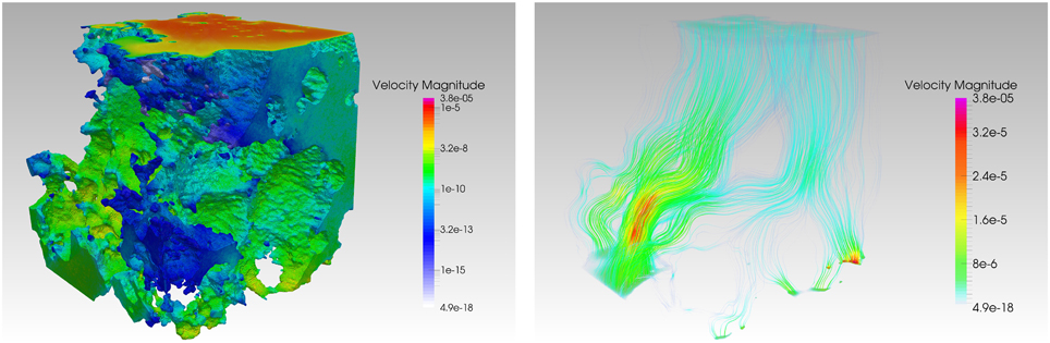
Figure 2. Left: The surface plot of the investigated volume of Sample B, colored according to the surface velocities. The values on the solid boundary are at least three orders of magnitude lower than the values on the outlet (top surface of the mesh). Right: The streamlines of the steady-state velocity field, generated for τ = 0.1, Δρ = 2.5 · 10−6. Both images were generated using ParaView 4.3.1. [32].
In order to construct the tetrahedral meshes, the initial triangular surface meshes were produced using the marching cubes isosurface as implemented in ImageJ [15]. The resolution of those surface meshes is the same as in the corresponding tomographic data (1 voxel accounting for 1-2 triangles). A tetrahedral volume mesh was constructed from the surface mesh using Tetgen [16].
2.2. Unstructured Lattice Boltzmann Method
The appeal of the lattice Boltzmann method to the geophysics research lies in its ability to model and simulate several types of phenomena related to reactive fluid flow in porous rocks: single and multiphase flows [17], unsteady flows [18], flows in complex geometries [19, 20] at a wide range of Reynolds numbers, as well as chemical processes, such as dissolution and precipitation [21]. For our experiments, we have used a variant of the finite element, off-lattice Boltzmann method [22], which uses the characteristic based integration, first proposed by Zienkiewicz and Codina [23]. We chose this method over the finite volume approach [10, 24] due to its improved stability. The characteristic based, off-lattice Boltzmann method has been specifically designed to remove the coupling between the positions of the computational grid's nodes and the discrete set of velocities, while retaining the stability of the standard, regular grid-based approach. The new scheme is derived directly from the spatio-temporal continuous formulation of the lattice Boltzmann equation
where fi(x, t) is the particle velocity distribution along the i-th discrete direction, ci is the associated discrete velocity, and Ωi is the collision operator, accounting for the rate of change of fi due to collision. We have employed the two relaxation time collision (TRT) operator [19, 25], which is a special case of a multi relaxation time collision operator (MRT, [26]), most commonly used in the lattice Boltzmann studies of porous flow due to its improved treatment of the solid boundary conditions in comparison to the standard, single relaxation time Bhatnagar-Gross-Krook (BGK) operator [19].
2.2.1. Integration Along Characteristics
Integrating Equation (1) along the characteristic curves and approximating the right-hand side yields
where n denotes the time step (iteration number), 0 ≤ θ ≤ 1 refers to the choice of the time integration method for the collision operator (0 for fully explicit, 1 for fully implicit, 0.5 for Crank-Nicolson), fni(x) = fi(x, tn), and fn + 1i(x) = fi(x, tn+ δt). In the general case of a MRT collision operator Ωi(f(x, t)) = ∑jAij(feqj − fj) [26] the implicit character of Equation (2) can be removed by introducing new variable
and expressing the collision operator in terms of g [22]
As the collision operator preserves both mass and momentum, the moments of gi equal corresponding moments of fi, ∑igi = ρ, ∑igici = ρu, hence also geqi = feqi. Finally, Equation (2) becomes
where the modified collision matrix reads = (I + δtθA)−1A. By substituting A by ABGK = τ−1I, which corresponds to the single relaxation time BGK collision operator, one readily obtains BGK = (τ + θδt)−1I. The resulting shift in the effective relaxation time = τ + θδt accounts for the unconditional stability of the Crank-Nicolson method and the implicit Euler method, since the condition δt < 2 is always fulfilled as long as θ ≥ and τ > 0. The standard Courant-Friedrichs-Lewy restriction on δt still applies.
2.2.2. Finite Element Scheme
In order to solve Equation (5) numerically on an unstructured grid, one has to be able to express the value of gn+1i at a given point x* in terms of the value of gni (and its derivatives) evaluated one time step earlier, at the same point. In order to enhance stability, this is typically done by the second order Taylor expansion of gni(x* − ciδt) [22, 23]
After applying the same approximation to the equilibrium distribution function, Equation (5) takes the following form
which is now suitable for discretization in space using the Galerkin finite element method. Here, the spatial decomposition using linear, tetrahedral elements has been applied. The modified particle distribution functions are sampled at the nodes (vertices) of the tetrahedral mesh, and interpolated at other points
where is the approximate solution, is the vector storing the values of at all vertices in the mesh, whose positions are v1, v2, …, vNV. Furthermore, ϕ(x)T = [ϕ1(x), ϕ2(x), …, ϕNV(x)], where ϕk(x) is a piecewise-linear shape function (also known as a hat or tent function) associated with the vertex k, i.e., ϕk(vj) = δjk, and ϕk is linear over each tetrahedral element. By applying the Bubnov-Galerkin method, we finally obtain the discrete, weak form of Equation (7)
where matrices M, Ci, Di ∈ ℝNV × NV are defined as
2.2.3. Boundary Conditions
The quality of any lattice Boltzmann simulation hinges on the choice of the boundary conditions used both on the solid and open boundaries. In this work, we have used a recent formulation of the solid boundary conditions for high Reynolds number flows, first proposed by Chikatamarla and Karlin [27]. Similarly to the popular bounce back method, the first step is to determine the subset D of the discrete directions that are corresponding to the “missing” populations (i.e., point away from the solid phase and into the fluid phase). The procedure for finding such subset in an unstructured grid setting is described in detail in Misztal et al. [10]. By setting the target values of the density ρtg and velocity utg at the boundary node, the local populations are recovered using the following rules
where ρ = ∑i∈Dfeqi(ρtg, utg) + ∑i∉Dfi, and ρu = ∑i∈Dcifeqi(ρtg, utg) + ∑i∉Dcifi. In our simulations we assumed no-slip boundary condition on the static, solid walls, corresponding to utg = 0. The value of ρtg can be estimated either by using the bounce back method or, if the former approach fails (depending on the local geometry of the solid boundary), by extrapolating the values of density from the neighboring bulk nodes. We have observed that this choice of the solid boundary condition formulation yields significantly more stable simulations of flows with lower values of the kinetic viscosity and higher Reynolds number, compared to the bounce back method.
The boundary conditions at the inlet and at the outlet can also be implemented using the same procedure. We have chosen to use pressure boundary conditions, specified by the constant pressure values: pin at the inlet, and pout at the outlet; pin > pout. Since p = c2sρ in the lattice Boltzmann method, this is equivalent to setting ρtg = pin/c2s at the inlet and ρtg = pout/c2s at the outlet (like most authors, we use c2s = 1/3). The values of utg at the open boundary nodes can be approximated using the averaged values of the velocity at the neighboring bulk nodes.
3. Results
The unstructured lattice Boltzmann method allows us to robustly compute single phase flow fields in arbitrary, complex channel networks for a wide range of flow parameters. In this section, we apply this method to study the flow in each of the natural porous samples described in Section 2.1. We then use the precomputed flow fields to study pollutant dispersion in the samples.
3.1. Steady-State Flow Computation
Our first goal is to compute the steady state flow in each porous rock sample due to applying a constant pressure difference between the inlet and the outlet planes. The particle distribution functions are initialized with the equilibrium distributions corresponding to ρ = 1, u = 0 in the entire mesh. For a given time step δt, relaxation time τ, and constant inlet and outlet densities ρin = 1 + Δρ and ρout = 1, we run the lattice Boltzmann simulation until the steady state is reached. In order to detect when steady-state has been reached, we compute the inlet flow rate Qin by evaluating the following integral numerically at every time step tn
where the sum on the right-hand side is over each inlet triangle Tk; up, uq, ur are its nodal velocities, nk is the unit-length normal vector to Tk, and Ak is its area. The outlet flow rate Qout is evaluated the same way. The simulation ends when |Qin(tn+1) − Qin(tn)| < ϵ|Qin(tn)| and |Qout(tn+1) − Qout(tn)| < ϵ|Qout(tn)|, where ϵ = 10−5.
Examples of the obtained velocity fields in each of the porous samples are shown in Figures 1, 2. In Figure 3 we present the typical convergence plots for Qin and Qout in our simulations. The initial oscillations are caused by the discontinuous initial conditions, as well as the formulation of the open boundary conditions; setting ρin = 1 + Δρ gives rise to a shock wave, which first travels to the outlet, and gets reflected off the outlet and inlet planes, while its amplitude decays exponentially. Once the pressure wave vanishes, the values of Qin and Qout continue to converge exponentially to the steady state values Q∞in and Q∞out. We expect these values to be equal, however, since the expression (12) is only first-order accurate, we observe a small difference between these two values, which is particularly evident in case of the more coarsely meshed Sample A. We have performed steady-state flow computation for Δρ ranging from 2.5 · 10−7 to 2.5 · 10−3, and relaxation times τ = 0.01 − 0.1, and we have obtained stable results obeying the Darcy's law, which states that under steady-state flow conditions, the flow rate Q through a given cross section is proportional to the pressure drop Δp = c2sΔρ that drives the fluid.
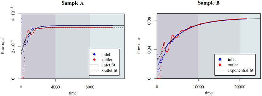
Figure 3. Convergence plot for the steady-state computation in Sample A (on the left, τ = 0.02, Δρ = 10−6) and in Sample B (on the right, τ = 0.1, Δρ = 2.5 · 10−6). The exponential fits are computed in R, using robust nonlinear regression, after weighting out the initial, oscillatory phase (flow rates and time are given in lattice Boltzmann units).
These simulation results shown in Figures 1, 2 correspond to a Reynolds number approximately equal to 0.01. The velocity in the figures is expressed in lattice Boltzmann units uLB. By dimensional analysis we can express the velocity in another arbitrary system of units according to the following transformation
where the lLB and νLB are the system size and kinetic viscosity in lattice Boltzmann units, lSU and νSU are the same quantities expressed in another system of units. If the fluid is water, substituting the real-world parameters into Equation (13) yields the following scaling formulas for the real-world velocities in the SI system of units: uSI = uLB · 6000 in Sample A, and uSI = uLB · 600 in Sample B.
3.2. Dispersion in Porous Samples
Having computed the steady state flow field in each of the porous rock samples, we obtain the Lagrangian trajectories of passive tracers, which satisfy
in the absence of molecular diffusion. The solution of the above equation is fixed by the initial position xk(0). From these Lagrangian trajectories we study the statistics of the separation dkj(t) = xk(t) − xj(t) between two fluid particles, which initially are close to each other. The separation of particles obeys the differential equation
The constraints imposed by the porous heterogeneous structure may cause non-smooth velocity fields due to the intrinsic branching of channel connectivity, leading to broad distribution of velocities and absence of decorrelation in time. For non-smooth velocity fields we might have, for instance, that the velocity difference between two points scales as |u(xk(t)) − u(xj(t))| ∝ |xk(t) − xj(t)|β = dβkj, with β < 1, as in the inertial range in turbulent flows. Multiplying the left and right hand sides terms in Equation (15) by dkj(t) and substitution of the latter scaling lead to
whose solution for finite time gives the behavior
As seen in Figure 4, we find from a flow simulation in Sample A that β ≈ 1/3, which coincides with Richardson dispersion law. Of course, such spatial scaling should not be associated to the classical Richardson-Kolmogorov cascade picture. Instead, the anomalous dispersion originates from the high degree of heterogeneity in Sample A and the broad distributions of pore sizes. This is further confirmed by the simulations performed in Sample B, here we see a particle separation in time, which is consistent with ballistic motion of particles in a more simple geometry. This is due to the fact, that the flow in Sample B is dominated by one large pore and the heterogeneity of the much smaller neighboring pores is only having a negligible impact on the averaging (see Figure 4).
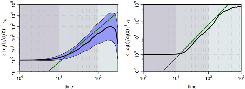
Figure 4. The black line shows the change with time of the average of the squared distance of particles, which initially are closer than 1% of the system size (the linear size). In the left panel, we show data from Sample A. The green dashed line is proportional to t3 and is consistent with the Richardson dispersion law. Despite the limited scaling region, we see an anomalous dispersion, where particles separates faster than in a ballistic regime. The envelope surrounding the black line shows the standard deviation of individual particle pairs. In the right panel, we show similar data for Sample B. The dashed line is here proportional to t2 and is therefore consistent with a ballistic separation of particles.
3.3. Evacuation of Particles through Advection and Diffusion
In our final experiment, we apply the previously obtained steady state velocity field u(x) in a study of pollutant removal from Sample A. In particular, we perform a comparative, qualitative study of particle evacuation rate from the porous sample, using two different flushing strategies: through continuous steady flow and through the use of rectangular pulses of equal width and amplitude, increasing period and decreasing duty cycle (see Figure 5).
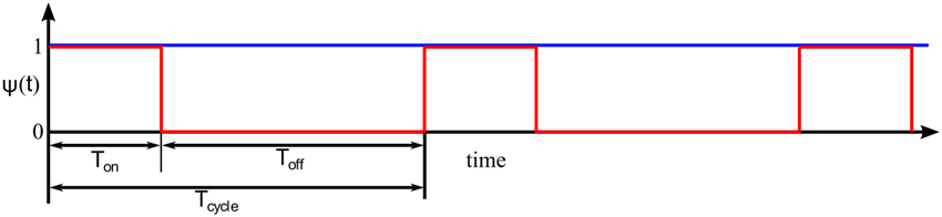
Figure 5. Continuous (blue) and rectangular pulse envelope (red). The pulse width Ton is constant in all our particle evacuation simulations, and we run the simulations with three different pulse separation times Toff. The duty cycle is defined as d = Ton/Tcycle. The pulse separation time Toff is on the order of 10% of the diffusive time, defined as R2/D, where R is the characteristic pore size, and D is the diffusivity.
As the first step of this numerical experiment, we randomly seed a large number of particles N0 (in our experiments N0 = 250,000), uniformly distributed in the pore space of the sample. We assume that the particles are passively advected by the fluid, but also undergo molecular diffusion. The motion of such passive tracers is described by the following Langevin equation
where xk(t) is the position of the kth particle at time t, and u(xk(t), t) = u(xk(t))ψ(t) is the fluid's velocity evaluated at particle's position at time t; ψ(t) is the pulse envelope function. Here we assume that the frequency of the pulses is smaller than the inverse of the characteristic time in which viscous effect are propagated inside the porous sample. The latter can be estimated as R2/ν, where R is on the order of the largest channel width. The final term, , is the random “kick” function, where D is the diffusivity and ξk(t) is a vector-valued Gaussian noise with mean amplitude equal to unity, whose correlation is given by 〈ξk(t) ξk′(t′)〉 = δkk′δ(t − t′). The above equation for passive tracers can be obtained in the limit of vanishing Stokes time from the following system of Langevin equations describing the Brownian motion of inertial particles in a moving fluid [28]
in which τ is the Stokes time. We integrate Equation (18) for each particle using the forward Euler method. Additionally we assume elastic collisions between the particles and the solid wall, and that the particles which cross the outlet plane are removed from the system. Then, we track the number N of particles remaining in the pore space as a function of the total volume of fluid flushed through the system
The results of our experiments for Sample A are presented in Figure 6. The parameters were chosen so that the effective Péclet number Pe ≈ 1600. Evidently, continuous flushing is the least efficient in terms of the amount of resources used (water, energy) in order to remove a given fraction of pollutant from the sample. Increasing the separation between the pressure pulses yields increasingly more efficient use of resources. This is due to the fact that the water flow through the sample quickly decreases the particle concentration in the main channel network, however, some pores are inaccessible to the flow, i.e., u = 0 in such spaces. The only way for the particles to be released from these pores is through diffusion, and, as it is a slower process, increasing the pulse separation increases the time for diffusion to act on. In contrast, as the particle concentration in the main channel network decreases, the efficiency of continuous flushing quickly drops.
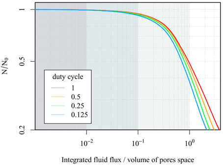
Figure 6. The fraction of the pollutant left inside Sample A as a function of the total volume of water that passed through the sample (given as a fraction of the pore space volume), using continuous flushing (duty cycle d = 1) and increasingly separated, constant width, rectangular pressure pulses.
4. Discussion
4.1. Evaluation of the ULBM
Our choice to use the unstructured lattice Boltzmann method, as opposed to the regular grid based approaches, was dictated by the higher flexibility and accuracy of the unstructured meshes at representing complex solid boundaries. Unlike regular grids, unstructured meshes allow for locating the nodes precisely at the boundary, yielding the boundary approximation error on the order of h2, as opposed to h in case of regular grids, where h is the grid spacing (or local edge length, in case of unstructured meshes). This error can be decreased further, without significantly increasing the problem size, by employing adaptive meshes, i.e., using higher precision (lower h) to resolve fine features, while keeping the mesh coarser in the regions where the boundary is almost flat, or where the flow field is approximately linear. Furthermore, unstructured meshes do not introduce extra memory overhead related to the storage of the solid phase elements, which is particularly beneficial in case of samples with low porosity. Overall, the number of volumetric elements required to represent a porous structure with precision h on the boundary scales like h−2 log h−1, as opposed to h−3 in case of basic regular grids. Certain techniques, such as the immersed boundary method [29] and hierarchical voxel structures [30], allow regular grid based approaches reach the effective storage efficiency similar to that of unstructured meshes. However, they increase the complexity of the fluid simulation method, and the lack of coupling between the nodal positions and the precise location of the solid boundary persists. As a consequence, boundary features finer than the minimum grid spacing cannot be represented correctly and, in the worst case scenario, the topology of the channel network might be ambiguous or inaccurate. In contrast, unstructured grids yield much simpler formulation of the boundary conditions, allow for a faithful representation of arbitrarily fine surface details, and reproduce the channel network topology exactly (although, in our case, the accuracy of the representation is still limited by the resolution of the tomographic data).
The benefits of the ULBM come at a cost of increased number of computations per grid node. At each time step, at a given node, regular grid based LBM requires a single evaluation of the collision term, one assignment (copy) operation and a single addition per each discrete direction. ULBM also requires just a single evaluation of the collision term per node, at every time step, however, the streaming and collision steps require averaging the values of fi and Ωi from all neighboring nodes, yielding 2(v + 1) additions and multiplications per each discrete direction, where v is the valency of the node. In the meshes used in our simulations, the average valency 〈v〉 ≈ 12 (Table 1). Finally, lattice Boltzmann methods compute the full temporal evolution of the flow and, when applied to the problem of finding the steady-state flow with constant pressure boundary condition, it converges asymptotically to the solution. Consequently, in this particular application, it can be outperformed by implicit, finite-element Stokes solvers, which typically require fewer sparse matrix multiplications (due to a lower number of variables, and a higher convergence rate). However, implicit Stokes solvers are unsuitable for simulations of unsteady flows, such as: multiphase flows, turbulent flows, flows influenced by moving solid boundaries or by oscillating pressure differences, all of which do not pose a great difficulty for the LBM. Furthermore, the LBM's convergence rate could be improved by employing more refined open boundary conditions, for example by specifying the velocity profile at the inlet, and using Grad's approximation [31] at the outlet.
5. Concluding Remarks
The complex pore geometry of most porous media is a significant obstacle for efficient numerical simulation of flow. We have here discussed the unstructured lattice Boltzmann method for fluid flow. We have used the method on a couple of rock samples and have in the sample with a more complex geometry observed an anomalous dispersion of Lagrangian particles without any particle diffusion introduced. One sample with a less complex pore space showed no sign of anomalous dispersion. We further showed that in the more complex parts of the pore space, diffusive transport might dominate over advective transport and therefore the evacuation of a pollutant might be, from a resource point of view, more effective if cycles of flushing water through the sample are used. Further simulations however would be needed to establish the most efficient strategy for pollutant removal.
Funding
Provided through the grant Earth Patterns from the Villum Foundation and by the Innovation Fund Denmark and Maersk Oil and Gas A/S through the P3 project. The Danish National Research Council (via Danscatt) provided support for the experimental work. AH acknowledges funding from the European Unions Seventh Framework Programme for research, technological development and demonstration under grant agreement no 316889. DM acknowledges funding from the People Programme (Marie Curie Actions) of the European Unions Seventh Framework Programme FP7/2007-2013/under REA grant no 297921.
Conflict of Interest Statement
The authors declare that the research was conducted in the absence of any commercial or financial relationships that could be construed as a potential conflict of interest.
Acknowledgments
We thank B. Vinter and J. Avery for help with improving the performance of the ULBM implementation, and S. Pedersen, K. N. Dalby and H. Suhonen for help with the experimental work at beamline ID22 at the European Synchrotron (ESRF).
References
1. de Anna P, Le Borgne T, Dentz M, Tartakovsky AM, Bolster D, Davy P. Flow intermittency, dispersion, and correlated continuous time random alks in porous media. Phys Rev Lett. (2013) 110:184502. doi: 10.1103/PhysRevLett.110.184502
2. Lester DR, Metcalfe G, Trefry MG. Is chaotic advection inherent to porous media flow? Phys Rev Lett. (2013) 111:174101. doi: 10.1103/PhysRevLett.111.174101
3. Kang PK, de Anna P, Nunes JP, Bijeljic B, Blunt MJ, Juanes R. Pore-scale intermittent velocity structure underpinning anomalous transport through 3-D porous media. Geophys Res Lett. (2014) 41:6184–90. doi: 10.1002/2014GL061475
4. Benson DA, Wheatcraft SW, Meerschaert MM. Application of a fractional advection-dispersion equation. Water Res Res. (2000) 36:1403–12. doi: 10.1029/2000WR900031
5. Mordant N, Delour J, Léveque E, Arnéodo A, Pinton JF. Long Time correlations in lagrangian dynamics: a key to intermittency in turbulence. Phys Rev Lett. (2002) 89:254502. doi: 10.1103/PhysRevLett.89.254502
6. Le Borgne T, Dentz M, Carrera J. Lagrangian statistical model for transport in highly heterogeneous velocity fields. Phys Rev Lett. (2008) 101:090601. doi: 10.1103/PhysRevLett.101.090601
7. Le Borgne T, Dentz M, Carrera J. Spatial Markov processes for modeling Lagrangian particle dynamics in heterogeneous porous media. Phys Rev E. (2008) 78:026308. doi: 10.1103/PhysRevE.78.026308
8. Lester DR, Metcalfe G, Trefry MG. Anomalous transport and chaotic advection in homogeneous porous media. Phys Rev E. (2014) 90:063012. doi: 10.1103/PhysRevE.90.063012
9. Le Borgne T, Dentz M, Villermaux E. Stretching, coalescence, and mixing in porous media. Phys Rev Lett. (2013) 110:204501. doi: 10.1103/PhysRevLett.110.204501
10. Misztal MK, Hernandez-Garcia A, Matin R, Sørensen HO, Mathiesen J. Detailed analysis of the lattice Boltzmann method on unstructured grids. J Comput Phys. (2015) 297:316–39. doi: 10.1016/j.jcp.2015.05.019
11. Cloetens P, Ludwig W, Baruchel J, Van Dyck D, Van Landuyt J, Guigay J, et al. Holotomography: quantitative phase tomography with micrometer resolution using hard synchrotron radiation x rays. Appl Phys Lett. (1999) 75:2912–4. doi: 10.1063/1.125225
12. Müter D, Sørensen H, Jha D, Harti R, Dalby K, Suhonen H, et al. Resolution dependence of petrophysical parameters derived from X-ray tomography of chalk. Appl Phys Lett. (2014) 105:043108. doi: 10.1063/1.4891965
13. Jha D, Sørensen HO, Dobberschütz S, Feidenhans R, Stipp SLS. Adaptive center determination for effective suppression of ring artifacts in tomography images. Appl Phys Lett. (2014) 105:143107. doi: 10.1063/1.4897441
14. Müter D, Pedersen S, Sørensen HO, Feidenhans'l R, Stipp SLS. Improved segmentation of X-ray tomography data from porous rocks using a dual filtering approach. Comput Geosci. (2012) 49:131–9. doi: 10.1016/j.cageo.2012.06.024
15. Schneider CA, Rasband WS, Eliceiri KW. NIH Image to ImageJ: 25 years of image analysis. Nat Meth. (2012) 9:671–5. doi: 10.1038/nmeth.2089
16. Si H. TetGen, a delaunay-based quality tetrahedral mesh generator. ACM Trans Math Softw. (2015) 41:11:1–11:36. doi: 10.1145/2629697
17. Huang H, Wang L, Lu XY. Evaluation of three lattice Boltzmann models for multiphase flows in porous media. Comput Math Appl. (2011) 61:3606–17. doi: 10.1016/j.camwa.2010.06.034
18. Pazdniakou A, Adler PM. Dynamic permeability of porous media by the lattice Boltzmann method. Adv Water Res. (2013) 62, Pt B:292–302. doi: 10.1016/j.advwatres.2013.06.001
19. Pan C, Luo LS, Miller CT. An evaluation of lattice Boltzmann schemes for porous medium flow simulation. Comput Fluids. (2006) 35:898–909. doi: 10.1016/j.compfluid.2005.03.008
20. Chang C, Liu CH, Lin CA. Boundary conditions for lattice boltzmann simulations with complex geometry flows. Comput Math Appl. (2009) 58:940–9. doi: 10.1016/j.camwa.2009.02.016
21. Kang Q, Zhang D, Chen S. Simulation of dissolution and precipitation in porous media. J Geophys Res. (2003) 108:2505. doi: 10.1029/2003jb002504
22. Bardow A, Karlin IV, Gusev AA. General characteristic-based algorithm for off-lattice Boltzmann simulations. Europhys Lett. (2006) 75:434–40. doi: 10.1209/epl/i2006-10138-1
23. Zienkiewicz OC, Codina R. A general algorithm for compressible and incompressible flow–Part I. the split, characteristic-based scheme. Int J Numer Meth Fluids. (1995) 20:869–85. doi: 10.1002/fld.1650200812
24. Rossi N, Ubertini S, Bella G, Succi S. Unstructured lattice Boltzmann method in three dimensions. Int J Num Methods Fluids. (2005) 49:619–33. doi: 10.1002/fld.1018
25. Talon L, Bauer D, Gland N, Youssef S, Auradou H, Ginzburg I. Assessment of the two relaxation time Lattice-Boltzmann scheme to simulate Stokes flow in porous media. Water Resour Res. (2012) 48:W04526. doi: 10.1029/2011WR011385
26. d'Humieres D, Ginzburg I, Krafczyk M, Lallemand P, Luo LS. Multiple-relaxation-time lattice boltzmann models in three dimensions. Philos Trans Math Phys Eng Sci. (2002) 360:437–51. doi: 10.2307/3066323
27. Chikatamarla SS, Karlin IV. Entropic lattice Boltzmann method for turbulent flow simulations: Boundary conditions. Phys A Statis Mech Appl. (2013) 392:1925–30. doi: 10.1016/j.physa.2012.12.034
28. Cardy J, Falkovich G, Gawedzki K, Nazarenko S, Zaboronski OV. Non-equilibrium Statistical Mechanics and Turbulence. Cambridge: Cambridge University Press (2008). doi: 10.1017/CBO9780511812149
29. Chen DJ, Lin KH, Lin CA. Immersed boundary method based lattice boltzmann method to simulate 2d and 3d complex geometry flows. Int J Modern Phys C. (2007) 18:585–94. doi: 10.1142/S0129183107010826
30. Stiebler M, Tölke J, Krafczyk M. Advection-diffusion lattice Boltzmann scheme for hierarchical grids. Comput Math Appl. (2008) 55:1576–84. doi: 10.1016/j.camwa.2007.08.024
Keywords: lattice Boltzmann method, flow in porous media, dispersion in porous media, unstructured grids, numerical modeling
Citation: Misztal MK, Hernandez-Garcia A, Matin R, Müter D, Jha D, Sørensen HO and Mathiesen J (2015) Simulating anomalous dispersion in porous media using the unstructured lattice Boltzmann method. Front. Phys. 3:50. doi: 10.3389/fphy.2015.00050
Received: 30 April 2015; Accepted: 25 June 2015;
Published: 08 July 2015.
Edited by:
Renaud Toussaint, University of Strasbourg, FranceReviewed by:
Francisco Welington Lima, Universidade Federal do Piauí, BrazilLaurent Talon, Université Paris XI, France
Amélie Neuville, International Research Institute of Stavanger, Norway
Copyright © 2015 Misztal, Hernandez-Garcia, Matin, Müter, Jha, Sørensen and Mathiesen. This is an open-access article distributed under the terms of the Creative Commons Attribution License (CC BY). The use, distribution or reproduction in other forums is permitted, provided the original author(s) or licensor are credited and that the original publication in this journal is cited, in accordance with accepted academic practice. No use, distribution or reproduction is permitted which does not comply with these terms.
*Correspondence: Marek K. Misztal, Niels Bohr Institute, University of Copenhagen, Blegdamsvej 17, Copenhagen DK-2100, Denmark, misztal@nbi.ku.dk