Density Measurements in Low Pressure, Weakly Magnetized, RF Plasmas: Experimental Verification of the Sheath Expansion Effect
 Yunchao Zhang
 Christine Charles
 Roderick W. Boswell
- Space Plasma, Power and Propulsion Laboratory, Research School of Physics and Engineering, Australian National University, Canberra, ACT, Australia
This experimental study shows the validity of Sheridan's method in determining plasma density in low pressure, weakly magnetized, RF plasmas using ion saturation current data measured by a planar Langmuir probe. The ion density derived from Sheridan's method which takes into account the sheath expansion around the negatively biased probe tip, presents a good consistency with the electron density measured by a cylindrical RF-compensated Langmuir probe using the Druyvesteyn theory. The ion density obtained from the simplified method which neglects the sheath expansion effect, overestimates the true density magnitude, e.g., by a factor of 3 to 12 for the present experiment.
1. Introduction
The electrostatic probe known as the Langmuir probe has been extensively used for plasma diagnostics in systems spanning electric propulsion [1, 2] down to semiconductor processing [3, 4] and biomedical applications [5, 6], due to its advantages of simple construction and accurate spatial positioning. A common parameter of interest in the wide range of electro-positive plasma applications is the plasma density n which is equal to the ion density ni and the electron density ne as a result of neutrality in the plasma, i.e., ne = ni = n. For ion density determination, the planar Langmuir probe (LP) is used to measure the ion saturation current Isat at a sufficiently negative biased voltage Vbias, where a high-voltage sheath forms in front of the probe tip repelling the electrons and collecting the ions. A widely used formula relating the ion density and ion saturation current, for low pressure plasmas of interest (typically less than tens of mTorr), is given by Merlino [7] and Chabert [8]:
where the constant coefficient of 0.6 represents the ratio of the ion density at the sheath-presheath interface to that in the bulk region, and assumes an absence of ion-neutral collisions across the presheath. This factor needs to be modified for high pressure plasmas where ion-neutral collisions play an important role in the presheath region [9]. is the geometrical area of the collecting disc of radius rp; e is the electron charge; is the Bohm velocity where Te and mi are the electron temperature (in the unit of volts) and the ion mass, respectively. It should be noted that, in this study the LP-related formulae refer to the one-side tip case and this setting is used by default unless otherwise specified.
Equation (1) simplifies the ion collection process by neglecting the sheath expansion effect [10–12] which states that, the actual ion collection area is effectively enhanced due to the existence of the high-voltage sheath around the probe tip. Additionally, previous studies [13], using finite element calculations and sheath front measurements, have shown that the expanded sheath could act as an electrostatic lens and focus the positive ions to distinct locations on the electrode surface. The sheath dimension is characterized by the Debye length with ϵ0 being the vacuum permittivity. When the plasma density is sufficiently high such that the Debye length is small compared to the tip radius (λD ≪ rp), the sheath expansion effect is negligible and Equation (1) is a valid method to obtain the ion density. However, for plasmas with a relatively low density magnitude and the Debye length being comparable to or larger than the tip radius (λD ≳ rp), the sheath expansion effect should be included and the validity of Equation (1) needs to be checked. The relation between a tip's sheath expansion area As and geometrical area Ap can be described by Sheridan's method [12, 14]:
where ηp = (ϕ−Vbias)/Te is defined as the dimensionless probe bias and ϕ is the plasma potential. The coefficients a and b are given by:
where rp/λD is defined as the dimensionless probe radius. In this case the ion saturation current is given by:
where a constant coefficient of 0.55 is used, which takes into account the curvature of the sheath edge [12]. Hence, for low pressure plasmas with rp/λD ≲ 1 and As/Ap > 1, the ion density obtained from Equation (1) would overestimate the more accurate value obtained from Equation (3).
Previous experiments [9, 14] have verified Sheridan's method (using particle-in-cell (PIC) simulations to obtain algebraic formulae for ion density correction [12]) in direct-current (DC) discharges by comparing the electron density and the corrected ion density measured through their respective saturation current by a single planar LP. Since the plasma breakdown voltage is lower for a radio-frequency (RF) power system compared to a DC system [15], most low pressure laboratory plasmas are sustained using a RF power supply according to Paschen's law. For electron density determination in such plasmas, the electron current part of LP-measured current-voltage (I–V) characteristic is distorted and the electron saturation current method loses validity [16]. The present study verifies the validity of Sheridan's method in determining plasma density in low pressure RF plasmas, by comparing the ion density obtained from Sheridan's method using a planar LP, and the electron density obtained from the Druyvesteyn theory using a cylindrical RF-compensated Langmuir probe (CP) [16, 17].
The Druyvesteyn theory [3, 10, 18] has advantages of being capable of measuring the energy distribution of non-Maxwellian electrons and being independent of the ratio of probe dimension to Debye length. On the other hand, the modeling of ion collection by a cylindrical probe (e.g., [9, 19]) requires the tip radius to be much smaller than the Debye length, which is violated under the present experimental condition. Hence the CP will not be used to obtain the ion density in this study and future PIC simulations, similar to the process reported in Sheridan [12], are need to correct the ion density measured by a cylindrical probe. The Druyvesteyn theory shows that the second derivative of electron current Ie with respect to biased voltage Vbias is proportional to the electron energy probability function (EEPF):
where Ac = πdplp (with dp and lp being the diameter and length of the cylindrical tip, respectively) is the collecting area of the cylindrical tip, and r is the position vector. The end surface of the cylindrical tip, , is neglected in Equation (4) due to Ae ≪ Ac (dp ≪ lp). The second derivative of the electron current can be obtained through two analog differentiators [16, 17], i.e., with respect to time t, the sweeping signal of biased voltage must be a linear function of time (generated by a triangular voltage source) such that . The electron density and electron temperature are derived from the EEPFs using:
It should be noted that for the present experiment, a static magnetic field is used to confine the plasma. When the average Larmor radius of ions is much larger than the radius of the planar LP, and the average Larmor radius of electrons is much larger than the radius of the cylindrical CP, the magnetic effect on the orbital motion of charged particles toward the probe tip can be neglected, i.e., the plasma is weakly magnetized for probes. In this case, Sheridan's method (used for the planar LP) and the Druyvesteyn theory (used for the cylindrical CP) will be valid methods to measure the ion density and electron density, respectively.
2. Experimental Setup
The experiment is carried out in the Chi-Kung reactor shown in Figure 1A which, on the left hand side (z < 0 cm), consists of a cylindrical plasma source terminated with an aluminum earthed plate and on the right hand side (z > 0 cm), a contiguously attached 30-cm long, 32-cm diameter, earthed aluminum diffusion chamber. The plasma source is made of a 31-cm long, 13.7-cm diameter Pyrex glass tube surrounded by a 18-cm long double saddle antenna (its configuration has been detailed in Chi et al. [20]) operating at a constant RF power of 310 Watts at 13.56 MHz, for which a L-type network is used to match the plasma discharge to a RF power supply. A turbo/primary pumping system is used to obtain a base pressure of 3 × 10⁻⁶ Torr in the reactor monitored with an ion gauge. Argon gas is fed to the system through a side wall port of the diffusion chamber yielding a constant low pressure of 0.5 mTorr measured with a Baratron gauge attached to the chamber.
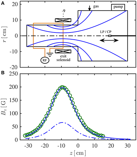
Figure 1. (A) Chi-Kung reactor implemented with a convergent-divergent magnetic field, showing major components and diagnostic probes. The calculated magnetic field lines are plotted as solid curves within the reactor geometry. (B) On-axis magnetic flux density Bz generated with the 9-A high solenoid current, measured using a gaussmeter (open circles) and calculated from the Biot-Savart law (solid line), and calculated results for the 3-A low solenoid current (dash-dotted line).
A solenoid close to the source exit is used to generate a convergent-divergent magnetic field and the field lines calculated from the Biot-Savart law are shown in Figure 1A as solid curves. When a current generated from the DC power supply is transmitted into the solenoid, defined as the “solenoid current", it is divided equally into the two parallel coils due to the double-coil-wound arrangement which has been used to resolve the heating issue caused by a large current flowing through the solenoid. The magnetic flux density on the central axis (Bz = B) for a solenoid current of 9 A is measured by a gaussmeter and the data, represented by open circles in Figure 1B, show a maximum of 200 Gauss at z = −9 cm (location of the magnetic throat) and a symmetric decrease to tens of Gauss in the top region of the plasma source and in the diffusion chamber. Calculated results for the 9-A high solenoid current, represented by the solid line, are consistent with the gaussmeter measurements, and the results calculated for the 3-A low solenoid current are given as the dashed line. Previous experiments [21] have shown that the plasma can be sustained under two magnetic-field-induced modes: a high field mode represented by the solenoid current case of 9 A and a low field mode represented by the solenoid current case of 3 A. For both field modes, the magnetic field strength satisfies that the average Larmor radius of ions (on axis, rci > 7 mm for the high field mode and rci > 21 mm for the low field mode) is much larger than the radius of the planar LP (rp = 0.95 mm), and the average Larmor radius of electrons (on axis, rce > 0.5 mm for the high field mode and rce > 1.5 mm for the low field mode) is much larger than the radius of the cylindrical CP (rp = 0.125 mm). Hence the magnetic effect on the orbital motion of charged particles toward the probe tip can be neglected, and Sheridan's method and the Druyvesteyn theory are valid to interpret the collection process of charged particles. It should be noted that a detailed description of charged particle motion onto differently orientated probes in weakly magnetized plasmas is beyond the scope of this study. Here it is simply noted that under the present experimental condition rotation of the probes about their axes changes the measurements by only a few percent, and hence the effect of probe orientation is negligible.
A vacuum slide is mounted on the back plate terminating the diffusion chamber to allow positioning of the probes along both the axial and radial directions without breaking vacuum, except when changing the probe. For the present experiment, probe measurements are only taken along the central axis. Two electrostatic probes are used to obtain the plasma density: a planar LP to measure the ion density ni and a cylindrical CP to measure the electron density ne, with their probe shafts and the reactor walls being grounded to a common earth. The planar LP, similar to the design reported in Lafleur [22], consists of a 1.9-mm diameter nickel disc mounted perpendicularly to the axis of a ceramic tube. The back side of the disc and the hollow behind are covered with ceramic adhesive, and only the front side of the disc is facing the plasma source and interacting with the plasmas. The probe tip is biased sufficiently negative such that the electrons are repelled from the disc region and only the ions are collected to give the ion saturation current Isat. The cylindrical CP, similar to the design reported in Takahashi et al. [17], consists of a 6-mm long, 0.25-mm diameter tungsten wire tip (the wire orientation being arranged perpendicularly to the axial direction to maximize the collection area), a series of RF chokes resonating at 13.56 and 27.12 MHz (housed inside a glass pipette tube) and a reference electrode to suppress the signal distortion caused by sheath rectification in front of the probe tip in RF plasmas [16, 17, 23]. By using this configuration, the CP obtains a reliable measurement of the electron current component Ie in the I–V characteristic.
3. Results and Discussions
In order to check the reliability of ion density measurements in RF plasmas using Sheridan's method, the on-axis ion density ni at z = −9 cm (location of the magnetic throat) is given at different biased voltages Vbias for each magnetic mode, calculated from the simplified method using Equation (1) and from Sheridan's method using Equations (2) and (3). For the high field mode (Figure 2A), the ion density obtained from the simplified method (solid circles) decreases by about 30% as the biased voltage increases from −95 V to −30 V, due to the uncorrected sheath expansion effect, while the corrected ion density obtained from Sheridan's method (open circles) keeps constant. The low field mode (Figure 2B) exhibits a similar result to the high field mode, showing that Sheridan's method is capable of correcting the sheath expansion effect around a planar LP in low pressure, weakly magnetized, RF plasmas.
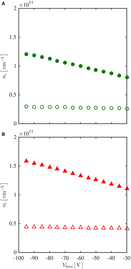
Figure 2. Correlation data between ion density ni and biased voltage of LP Vbias at z = −9 cm, r = 0 cm, for (A) high field mode and (B) low field mode, using Sheridan's method [Equation (2) and (3), open markers], and using the simplified method (Equation (1), solid markers).
The dimensionless probe bias ηp and the electron temperature Te (which is used to calculate the Bohm velocity) are parameters of Equation (3) and their on-axis profiles obtained from the CP, are plotted on Figure 3. The probe bias (Figure 3A) is about 15 and ranges between 14 and 18 for both the high field mode (open circles, generated with the 9-A solenoid current) and low field mode (open triangles, generated with the 3-A solenoid current). For the high field mode, the electron temperature (represented by open circles in Figure 3B) has a maximum value of about 9 V at the magnetic throat at z = −9 cm and deceases to about 8 V toward the end of the source exit and about 7 V at z~10 cm into the diffusion chamber. For the low field mode, the electron temperature (represented by open triangles in Figure 3B) exhibits a top region of about 9.5 V close to the middle of the plasma source and decreases to about 8 V located 10 cm into the diffusion chamber. Substituting these data and the LP-measured ion saturation current Isat biased at Vbias = −95 V into Equations (2) and (3) yields the on-axis ion density profile shown in Figure 4. The high field mode (represented by open circles in Figure 4A) shows a peak value of about 3 × 1010 cm−3 at the magnetic throat, similar to its electron temperature profile of Figure 3B; the low field mode (represented by open triangles in Figure 4B) presents a maximum value of about 6 × 1010 cm−3 near z = −15 cm.
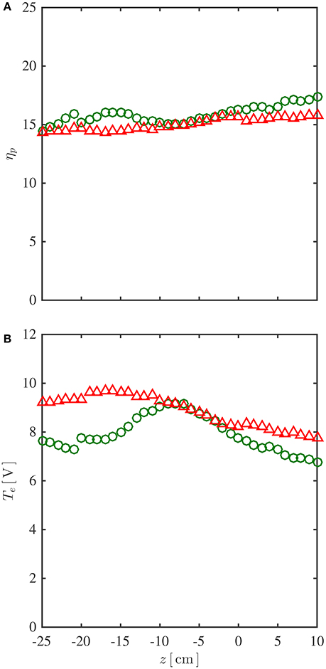
Figure 3. On-axis profiles of (A) dimensionless probe bias ηp and (B) electron temperature Te obtained from the RF-compensated Langmuir probe (CP), for high field mode (open circles) and low field mode (open triangles).
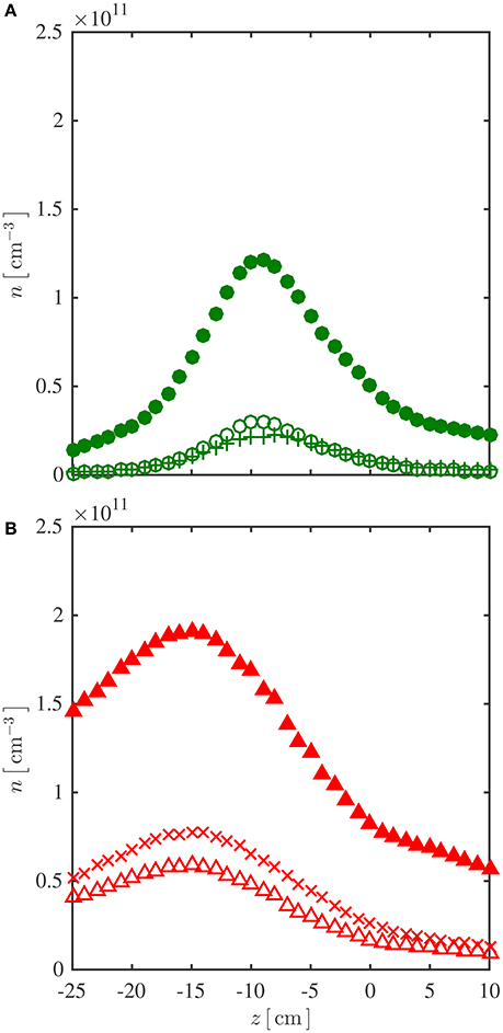
Figure 4. (A) High field mode, on-axis profiles of LP-measured ion density ni obtained from Sheridan's method [Equations (2) and (3), open circles], and from the simplified method [Equation (1), solid circles], and CP-measured electron density ne from the Druyvesteyn theory [Equation (5), pluses]. (B) Low field mode, on-axis profiles of ion density obtained from Sheridan's method (open triangles) and from the simplified method (solid triangles), and electron density from the Druyvesteyn theory (crosses).
The ion density profile calculated from the simplified method, using Equation (1) which neglects the sheath expansion effect, is given as solid markers in Figure 4. The data is about 4 to 12 times that obtained from Sheridan's method for the high field mode (Figure 4A) and about 3 to 6 times for the low field mode (Figure 4B). The high field mode's electron density profile, obtained from the CP using Equation (5) and represented by pluses in Figure 4A, is in close agreement with the ion density derived from Sheridan's method (open circles) and clearly does not match the data from the simplified method (solid circles). Similarly, the low field mode's electron density profile, represented by crosses in Figure 4B, is consistent with the ion density derived from Sheridan's method (open triangles) and drastically lower than that derived using the simplified method (solid triangles). Additionally, the Debye length λD derived from the density data on Figure 4, exhibits a value of about 0.15 mm in the high density region for both field modes, similar to the radius of the CP (rp = 0.125 mm). Since traditional theories on ion collection by a cylindrical probe [3, 9] require the tip radius to be much smaller than the Debye length, the CP will not be used to measure the ion density in the present experimental setup and the related mechanism for ion density correction is beyond the scope of this study.
In summary, these results clearly show the validity of Sheridan's method in low pressure, weakly magnetized, RF plasmas, stipulating that sheath expansion around the probe tip is an important factor in interpreting LP-measured ion density in such plasmas. Neglect of the sheath expansion effect could result in an unreasonable overestimate of the plasma density values. The ion density results obtained from the LP (using Sheridan's method) are in close agreement with the electron density results obtained from the CP (using the Druyvesteyn theory), which shows that the two probes present good consistency for plasma density measurements.
Author Contributions
CC and RB devised the project and designed the basic structure of the research. They both supervised YZ, their Ph.D student.
Funding
This research was partially funded by the Australian Space Research Program (APT project) and the Australian Research Council Discovery Project (DP140100571).
Conflict of Interest Statement
The authors declare that the research was conducted in the absence of any commercial or financial relationships that could be construed as a potential conflict of interest.
References
1. Goebel DM, Katz I. Fundamentals of Electric Propulsion: Ion and Hall Thrusters. JPL Space Science and Technology Series. New York, NY: John Wiley & Sons (2008).
2. Charles C. Plasmas for spacecraft propulsion. J Phys D Appl Phys. (2009) 42:163001. doi: 10.1088/0022-3727/42/16/163001
3. Lieberman MA, Lichtenberg AJ. Principles of Plasma Discharges and Materials Processing. 2nd Edn., New York: John Wiley & Sons (2005).
4. Donnelly VM, Kornblit A. Plasma etching: Yesterday, today, and tomorrow. J Vac Sci Technol A. (2013) 31:050825. doi: 10.1116/1.4819316
5. Fridman G, Friedman G, Gutsol A, Shekter AB, Vasilets VN, Fridman A. Applied plasma medicine. Plasma Process Polym. (2008) 5:503. doi: 10.1002/ppap.200700154
6. Kong MG, Kroesen G, Morfill G, Nosenko T, Shimizu T, van Dijk J, et al. Plasma medicine: an introductory review. New J Phys. (2009) 11:115012. doi: 10.1088/1367-2630/11/11/115012
7. Merlino RL. Understanding Langmuir probe current-voltage characteristics. Am J Phys. (2007) 75:1078. doi: 10.1119/1.2772282
8. Chabert P, Braithwaite N. Physics of Radio-Frequency Plasmas. Cambridge: Cambridge University Press (2011).
9. Robertson S. Sheaths in laboratory and space plasmas. Plasma Phys Control Fusion. (2013) 55:093001. doi: 10.1088/0741-3335/55/9/093001
10. Hershkowitz N. How Langmuir probes work. In: Auciello O, Flamm DL, editors. Plasma Diagnostics. Vol. 1 of Plasma-Materials Interactions. San Diego, CA: Academic Press Inc. (1989). p. 113.
11. Johnson JD, Holmes AJT. Edge effect correction for small planar Langmuir probes. Rev Sci Instrum. (1990) 61:2628. doi: 10.1063/1.1141849
12. Sheridan TE. How big is a small Langmuir probe? Phys Plasmas. (2000) 7:3084. doi: 10.1063/1.874162
13. Stamate E, Sugai H. Discrete focusing effect of positive ions by a plasma-sheath lens. Phys Rev E. (2005) 72:036407. doi: 10.1103/PhysRevE.72.036407
14. Lee D, Hershkowitz N. Ion collection by planar Langmuir probes: Sheridan's model and its verification. Phys Plasmas. (2007) 14:033507. doi: 10.1063/1.2715557
15. Smith HB, Charles C, Boswell RW. Breakdown behavior in radio-frequency argon discharges. Phys Plasmas. (2003) 10:875. doi: 10.1063/1.1531615
16. Godyak VA, Piejak RB, Alexandrovich BM. Measurement of electron energy distribution in low-pressure RF discharges. Plasma Sources Sci Technol. (1992) 1:36. doi: 10.1088/0963-0252/1/1/006
17. Takahashi K, Charles C, Boswell RW, Kaneko T, Hatakeyama R. Measurement of the energy distribution of trapped and free electrons in a current-free double layer. Phys Plasmas. (2007) 14:114503. doi: 10.1063/1.2803763
18. Godyak VA, Piejak RB, Alexandrovich BM. Probe diagnostics of non Maxwellian plasmas. J Appl Phys. (1993) 73:3657. doi: 10.1063/1.352924
19. Stamate E, Ohe K. Probe diagnostics of electronegative plasmas with bi-Maxwellian electrons. J Appl Phys. (2001) 89:2058. doi: 10.1063/1.1337590
20. Chi KK, Sheridan TE, Boswell RW. Resonant cavity modes of a bounded helicon discharge. Plasma Sources Sci Technol. (1999) 8:421. doi: 10.1088/0963-0252/8/3/312
21. Zhang Y, Charles C, Boswell R. Effect of radial plasma transport at the magnetic throat on axial ion beam formation. Phys Plasmas. (2016) 23:083515. doi: 10.1063/1.4960828
22. Lafleur T. Helicon Wave Propagation in Low Diverging Magnetic Fields. Canberra, ACT: The Australian National University (2011).
Keywords: low pressure RF plasma, plasma density, Langmuir probe, sheath expansion, Sheridan's method, Druyvesteyn theory
Citation: Zhang Y, Charles C and Boswell RW (2017) Density Measurements in Low Pressure, Weakly Magnetized, RF Plasmas: Experimental Verification of the Sheath Expansion Effect. Front. Phys. 5:27. doi: 10.3389/fphy.2017.00027
Received: 29 October 2016; Accepted: 27 June 2017;
Published: 11 July 2017.
Edited by:
Agnes Granier, Centre National de la Recherche Scientifique (CNRS), FranceReviewed by:
Eugen Stamate, Technical University of Denmark, DenmarkDan M. Goebel, Jet Propulsion Lab (NASA), United States
Copyright © 2017 Zhang, Charles and Boswell. This is an open-access article distributed under the terms of the Creative Commons Attribution License (CC BY). The use, distribution or reproduction in other forums is permitted, provided the original author(s) or licensor are credited and that the original publication in this journal is cited, in accordance with accepted academic practice. No use, distribution or reproduction is permitted which does not comply with these terms.
*Correspondence: Christine Charles, christine.charles@anu.edu.au