Vacuum Testing of a Miniaturized Switch Mode Amplifier Powering an Electrothermal Plasma Micro-Thruster
 Christine Charles
 Wei Liang2
  Juan Rivas-Davila
 Roderick W. Boswell
- 1Space Plasma, Power and Propulsion Laboratory, Research School of Physics and Engineering, Australian National University, Canberra, ACT, Australia
- 2Department of Electrical Engineering, Stanford University, Stanford, CA, United States
A structurally supportive miniaturized low-weight (≤150 g) radiofrequency switch mode amplifier developed to power the small diameter Pocket Rocket electrothermal plasma micro-thruster called MiniPR is tested in vacuum conditions representative of space to demonstrate its suitability for use on nano-satellites such as “CubeSats.” Argon plasma characterization is carried out by measuring the optical emission signal seen through the plenum window vs. frequency (12.8–13.8 MHz) and the plenum cavity pressure increase (indicative of thrust generation from volumetric gas heating in the plasma cavity) vs. power (1–15 Watts) with the amplifier operating at atmospheric pressure and a constant flow rate of 20 sccm. Vacuum testing is subsequently performed by measuring the operational frequency range of the amplifier as a function of gas flow rate. The switch mode amplifier design is finely tuned to the input impedance of the thruster (~16 pF) to provide a power efficiency of 88% at the resonant frequency and a direct feed to a low-loss (~10 %) impedance matching network. This system provides successful plasma coupling at 1.54 Watts for all investigated flow rates (10–130 sccm) for cryogenic pumping speeds of the order of 6,000 l.s−1 and a vacuum pressure of the order of ~2 × 10⁻⁵ Torr during operation. Interestingly, the frequency bandwidth for which a plasma can be coupled increases from 0.04 to 0.4 MHz when the gas flow rate is increased, probably as a result of changes in the plasma impedance.
1. Introduction
The global space industry and related research and development is being disrupted by many factors including the emergence of nano-satellites, such as the small standardized “CubeSats” (based on the 10 cm square unit or “1U”). The “Cubesat” platform aims specifically at reducing the risk and cost associated with researchers space missions and most essential components such as on-board computer, battery, communications and attitude control boards are now commercialized. Space inherently engages with a multitude of disciplines with plasma physics often playing an important role, whether directly (electric propulsion [1]) or indirectly (plasma processing of components and sensors used in the space sector [2]). There are a variety of concepts currently under development to provide propulsion for nano-satellites with some of the technology already under testing in orbit (resisto-jets, ion spray thruster, low power arcjet, hollow cathode thruster, pulsed plasma thruster [3–7]). A good example is the development by a university group of the micro cathodic arc jet with a recent satellite detumbling demonstration in orbit [3, 7]. The result of having on-board propulsion rather than only attitude determination control systems (reaction wheels, magnetorquers) would be satellites that survive longer, have a wider envelope of performance, and which can produce research data and commercial returns of greater quality and quantity, especially if formation flying and orbit maneuvers could be routinely achieved.
One candidate is the instant “on” Pocket Rocket electrothermal radiofrequency (rf) plasma thruster [8–10]. Neutral gas heating in Pocket Rocket mostly results from ion-neutral collisions in the bulk plasma (charge-exchange and elastic) and from heating at the plasma cavity radial walls [11]. While propellant heating and thrust production has now been demonstrated [12] and complemented by computational studies (computer fluid dynamics [13] and particle in cell [14] codes) following earlier analytical studies [15], Pocket Rocket's viability for space use will only be achieved by refinements to the radiofrequency [16] and gas [17] delivery systems to improve overall efficiency and footprint. Optimum operation and viability in space would require achieving pulsed plasma operation combined with pulsed gas operation.
A challenge inherent to most plasma systems used for space propulsion is plasma ignition as well as plasma stability or repeatability. Ignition follows the “U” shaped Paschen curve of the breakdown voltage vs. the pD (pressure–distance) factor with larger breakdown voltages required for dc plasmas compared to rf plasmas [18]. Typical rail voltage on a CubeSat is 3 or 5 Volts and plasma breakdown voltages a few hundred Volts for small devices (~ mm in size). While thrust control and thrust efficiency are essential parameters of interest, space qualification of any plasma system includes additional test on electromagnetic interference (to prevent possible damage to other electronic components of the spacecraft) or particulate contamination (i.e., of the solar panels). Hence detailed assessment of the power sub-system is critical early in the development phase of the discharge production. In laboratory plasmas, optimum plasma tuning is usually obtained by using an impedance matching network with variable capacitors. This cumbersome method can be replaced by a frequency variable network using small fixed ceramic capacitors which is best suited for space applications [19] due to its small weight and volume footprint.
The present experimental study focuses on the development and testing of a low weight (~150 g), small (10 cm by 10 cm by 1 cm), robust and efficient dc (direct current) to rf power supply for the 13 MHz Pocket Rocket electrothermal radiofrequency thruster over a power range of 1–15 Watts (obtained by a variation in the duty cycle of the pulsed operation) with argon as propellant. The power supply consists of a switch mode amplifier [20, 21] and impedance matching network for optimum plasma ignition, tuning and control. MiniPR operation is facilitated by having plasma ignition directly achieved at the resonant frequency and a linear increase of pressure variation (i.e., plasma volumetric heating) with input power. The present study is a critical step toward space-based experiments and the switch mode amplifier concept is scalable to much higher powers (a few kWatts) making the present configuration an essential proof of concept toward space use for any type of radiofrequency powered thruster (i.e., Helicon Plasma Thruster or radiofrequency gridded thrusters such as the Dual Stage Four Grid thruster). This technology can also be applied to the emerging field of plasma medicine which often makes use of low power cylindrical rf plasma jets [22], where portability, low footprint and simplified tuning procedures are desirable.
2. Experimental Set Up
Two experimental configurations are used to test the radiofrequency plasma micro-thruster operating with the miniaturized switch mode amplifier, a first configuration where both the amplifier and thruster are outside vacuum (as would be the case for most laboratory plasma experiments using a commercial radiofrequency generator) and a second configuration more representative of the conditions of space where both the amplifier and thruster are immersed in vacuum. Two separate vacuum chambers are respectively used for these “atmospheric pressure” and “vacuum” tests.
2.1. Atmospheric Pressure Test Configuration
The first experimental configuration consists of a previously described small diameter Pocket Rocket radiofrequency (rf at ~13.56 MHz) plasma thruster called MiniPR attached to the 1 meter-diameter 2 meters-long IRUKANDJI vacuum chamber equipped with a primary/turbo-molecular pumping system (Figure 1A). The IRUKANDJI base pressure is measured to be about 1.3 × 10⁻⁶ Torr using an ion gauge and a baratron gauge located half a meter downstream of the thruster. A cartoon of MiniPR is shown in Figure 1A and is fully described in Charles et al. [16, 23]: briefly, it comprises an 18 mm-long 1.5 mm inner diameter ceramic tube forming the plasma cavity and surrounded by a central annular 5 mm wide rf copper electrode and two grounded 3 mm-wide aluminum electrodes (forming the grounded 8.5 cm diameter aluminum housing), each separated by two macor rings (not shown on Figure 1 for clarity), one 3 mm-wide on the gas inlet side and the other 4 mm wide on the plasma exhaust side. A 40 mm-diameter 16 mm-long aluminum cavity which acts as gas plenum is fitted with a gas inlet, a viewing window and a 10 Torr Baratron gauge to measure the pressure increase when the plasma is turned on, a result of gas heating in this electro-thermal thruster [24].
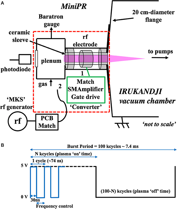
Figure 1. (A) Schematic of the MiniPR electrothermal radiofrequency plasma thruster body mounted onto the IRUKANDJI vacuum chamber flange with the two radiofrequency power systems external to vacuum and connected to the rf electrode: system (1) is the Converter switch mode amplifier (SMAmplifier) prototype with impedance matching network (Match) integrated on a PCB and system (2) is a variable frequency commercial MKS rf generator feeding a custom-made impedance matching network (PCB Match); (B) Signal applied to the gate drive board (Gate drive) feeding the switch mode amplifier MOSFET. The dotted red line square includes the parts (thruster and Converter) subsequently tested under WOMBAT vacuum (Figures 2, 3).
The rf electrode can be powered using either system (1) or system (2) shown on Figure 1A: system (1) consists of a newly developed switch mode amplifier (“SMAmplifier” on Figure 1A) feeding a low-loss solid-state impedance matching system (“Match” on Figure 1A) both mounted and integrated on a “CubeSat” nano-satellite formatted (10 cm by 10 cm by 1 cm) Printed Circuit Board (PCB) called “Converter.” The switch mode amplifier concept has been described elsewhere [20, 25, 26]: briefly it converts dc into rf by switching the gate signal (“Gate drive” on Figure 1A) of a Metal-Oxide-Semiconductor Field Effect Transistor (MOSFET) as in a Class E amplifier but has the ability to provide high efficiency, small footprint and reduced weight, key requirements for space use. System (2) is the reference laboratory radiofrequency set-up consisting of a custom-made miniaturized variable frequency solid-state matching network fed by a commercial (30–1,500 W MKS Spectrum) frequency adjustable (13.28–13.83 MHz) radiofrequency generator [16]. This impedance matching network was previously designed and implemented with a solenoid shape inductor [12, 16] with 12 loops. The solenoid inductor has magnetic field extending way beyond its physical volume, thus can induce high losses when placed near metal object as well as have electromagnetic interference with other components nearby: the power into MiniPR for system (2) is PMiniPR = γmatchloss (2)Pmks ~ 0.5Pmks.
However, this loss is minimized in the present Converter design by a two step approach. First, the matching inductor is implemented in a toroidal shape rather than solenoid, which contains the majority of its magnetic field within the torus. Normal toroidal shape inductors still have small portions of magnetic field outside the torus caused by a “one turn loop” of current along the circumference of the toroid from the input to the output terminal. To cancel the magnetic field due to the circumferential current, secondly, the matching inductor is also split equally into two toroidal inductors with same dimensions and turns but opposite current flowing directions [25, 26]. Vertically stacking the two halves cancels the axial direction magnetic field. Therefore, the matching inductor in the Converter has much lower stray magnetic fields and can be shielded with a copper layer without inducing high loss. The Converter PCB design yields a γmatchloss (1) of 0.9 so that the power into MiniPR for system (1) is PMiniPR ~ 0.9Pconv where Pconv is the Converter power output. All the inductors in this power supply prototype are made without magnetic cores, essentially air core, therefore their magnetic properties remain linear under high external magnetic fields conditions (no saturation) and high temperature (no Curie temperature limit). Moreover, all these air core inductors are printed using copper traces and vias within the PCB and the power supply results in a planar structure made of PCB conducive to side panel or structural frame of “CubeSat.” Further improvement such as using advanced PCB technologies (e.g., metal core, ceramic substrate, etc) can provide excellent mechanical strength as well as thermal dissipation capability for satellite applications. The main aim of this study is to characterize plasma coupling (ignition, continuous and pulsed operations) by the Converter specifically designed for operation with MiniPR over a power range of 1–14 Watts with a nominal power of typically 1.5 Watts, for gas flow rates in the 10–130 sccm range.
Argon propellant gas is introduced via the plenum, flows along the alumina tube and expands into vacuum but both the MiniPR structure and Converter are outside vacuum, i.e., at atmospheric pressure (Figure 1A). This first configuration allows basic plasma characterization via the plenum and signals monitoring on the PCB using a 20:1 voltage probe (Keysight N2875A) and a 4 channel oscilloscope (SIGLENT SDS2204X 300 MHz): the main plasma diagnostics are the plenum pressure and total light intensity emitted by the plasma measured using a silicon photodiode (RS 303-674 DU) pointing at the plenum window. The main switch mode amplifier controls are operational frequency and power by the use of a gate drive signal shown on Figure 1B. The switch mode amplifier described in detail in Liang et al. [25] has a ϕ2 topology and the present set-up makes use of a two channel power supply (for the Converter and gate circuits, respectively) and a pulse generator (for the efficient zero voltage switching operation of the converter MOSFET transistor's gate): the Converter signal is voltage limited to Vconv = 20 V and draws a current Iconv. The gate signal is voltage limited to Vgate = 14 V and draws a current Igate. A TTi CPX400A power supply is used to provide these voltages and measure Iconv and Igate. It is the switching of the gate using a pulse generator (SIGLENT SDG5162) between 0 and 5 V which effectively creates the radiofrequency signal shown in Figure 1B: a constant pulse width of 30 ns yielding a ~30% duty cycle of one individual period (about 74 ns) is applied onto the gate voltage (changing it only effects the operation efficiency of the Converter). The power control is obtained by adjusting the number of kcycles from 10 to 90 with the Converter bursting on and off at a period of 7.4 ms (about 100 kcycles), so that the average power is times the full power (CW mode). The full power refers to the power associated with the state that the Converter runs continuously with zero time off, which corresponds to the maximum 100 kcycles (defined as CW mode). At its optimum frequency, the prototype is designed to provide a high Q factor and a maximum peak to peak voltage of about 600 V at the MiniPR electrode, ensuring plasma ignition. Red insulating varnish (Model 10-9002-A from GC electronics) is applied to insulate the high voltage parts on the PCB surface. The total average dc input power into the PCB can be directly calculated from the measurements of Iconv and Igate:
The Converter has a measured efficiency of about 88%. Since the estimated matching network efficiency γmatchloss (1) is 90%, the Converter input to MiniPR has an estimated efficiency of 80% (PMiniPR ~ 0.8IconvVconv with Iconv and Vconv the Converter current and voltage, respectively). Although the Converter and gate circuits can be as light as 5–10 g using advanced 3D printing technology [27], this structurally supportive PCB design weighs 150 g intended for use as side panels or structural frames of “CubeSats.” Here the additional power IgateVgate needed to drive the gate is 17% of the total power < Pdcboard >, i.e., for CW mode PMiniPR = 13.44 W and Pgate = 2.8 W.
2.2. Vacuum Test Configuration
Vacuum testing is carried out in the 1 meter-diameter 2 meters-long WOMBAT vacuum chamber [12] recently upgraded with a new vacuum pumping system (scroll, turbomolecular and cryogenic pumps) and a suite of access and viewing ports (Figure 2). In this second configuration both MiniPR and the Converter are inserted in WOMBAT vacuum so as to provide three unobstructed views of the Converter, the plasma via MiniPR plenum window and the plasma exhaust plume, respectively. A gas feedthrough and a multi-coaxial feedthrough are used with the pulse generator and two channel power supply placed outside vacuum. The complete gas line consists of a flow controller placed outside the vacuum system, the gas line feed-through mounted on WOMBAT and a 1.5 m long 3 mm inner diameter plastic tube for direct gas injection into the plenum cavity. The WOMBAT base pressure measured using an ion gauge and a baratron gauge located 2 m downstream of the thruster is about 2 × 10⁻⁶ Torr under turbo-molecular pumping and 2 × 10⁻⁷ Torr under cryogenic pumping, respectively. The purpose of this vacuum testing is to investigate the presence or not of potentially destructive parasitic discharges on the PCB, to study the frequency range over which the plasma can be coupled at various flow rates and to qualitatively assess the reliability of the Converter components. Figure 3 shows a photo of plasma operation with both the thruster and PCB Converter immersed in vacuum.
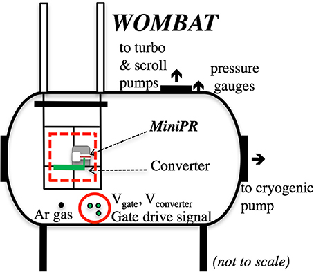
Figure 2. Schematic of the WOMBAT vacuum chamber showing the MiniPR thruster and Converter assembly (dotted red line square shown in Figure 1A).
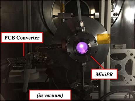
Figure 3. Plasma testing in WOMBAT of the MiniPR thruster powered by the Converter PCB, both in vacuum.
3. Results and Discussion
Experimental characterization of the miniaturized switch mode amplifier (with integrated impedance matching network) powering the MiniPR plasma micro-thruster needs to demonstrate that both continuous and pulsed plasma operation can be achieved using variable frequency tuning, that changes in the gas flow rate and duty cycle in pulsed operation yield thrust control and finally that plasma ignition and optimum power efficiency (i.e., as provided by the Converter design) can be achieved in conditions representative of space (i.e., in vacuum).
3.1. Frequency Tuning
Basic characterization of the discharge vs. Converter frequency is carried out using optical emission spectroscopy and the IRUKANDJI atmospheric pressure test configuration of Figure 1: the voltage measured by a photodiode placed against the plenum window (Figure 1A) and connected to a multimeter is shown in Figure 4 as a function of Converter frequency (constant pulse width of 30 ns as shown in Figure 1B) for 19 sccm of argon flow giving a “plasma off” pressure of about 3.5 Torr and for full power, i.e., continuous CW mode. Maximum plasma emission intensity is observed near the frequency for which the Converter has been specifically designed (~13.17 MHz giving maximum Converter current and power output of PMiniPR ~ 13.44 W). The gate current is 0.2 A during measurement in CW mode yielding a gate power of 2.8 W. The plasma was kept “on” between measurements, in CW mode for the open red symbol data sets and in pulsed mode at 20 kcycles for the filled black symbol data sets of Figure 4. Although the plasma can be maintained over a broad frequency range (± 0.5 MHz) extending the results previously reported for system (2) [16], there are two limitations to consider: for pulsed conditions (less than 100 kcycles and lower average dc power) the frequency range is reduced (i.e., ± 0.2 MHz at 20 kcycles corresponding to PMiniPR ~ 3 W). Since the Converter is non-linear, variation in frequency will affect the rf electrode voltage and plasma breakdown [18]; this is illustrated by measuring the time necessary for plasma ignition vs. frequency shown in Figure 6 for 20 kcycles. The usable range of frequency operation is considerably reduced as expected due to the fine tuning and design of the Converter to the impedance of MiniPR (~16 pF). The resonance frequency for this Converter design is 13.16–13.17 MHz which provides plasma ignition for powers down to 1–2 Watts. This result shows significant operational, efficiency and footprint improvement compared results previously reported for system (2) [16].
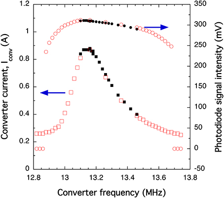
Figure 4. Converter current Iconv (open red squares and filled black squares) and photodiode voltage (open red circles and solid black dots) vs. operating frequency for the IRUKANDJI atmospheric pressure test configuration of Figure 1; gas flow rate is 19 sccm with CW operation at PMiniPR ~ 14 W; the plasma is kept “on” between measurements, in CW mode for the open red symbol data sets and in pulsed mode at 20 kcycles for the filled black symbol data sets; the gate current is 0.2 A during CW measurement.
The results in Figure 4 show that a frequency decrease from 13.17 to 12.9 MHz is accompanied by a Converter current decrease of a factor of 3.2 and a photodiode signal decrease by only 20%, suggesting that once the plasma is “on,” operating at 12.9 MHz may be more efficient. This is likely the result of the interrelation between the “dc to rf inverter” part and the “impedance matching” part of the Converter [25–27]. For efficient operation of the combination, two conditions need to be met: firstly the resonance of the matching network impedance together with MiniPR plasma impedance has to be close to the frequency the inverter is designed for; secondly, the impedance presented to the inverter (the transformed impedance from the MiniPR plasma by the matching circuit) has to be close to what the inverter is designed for. Because it is a high Q matching network, any variations of the plasma impedance can lead to a change of transformed impedance seen by the inverter and efficiency.
3.2. Radiofrequency Power Control
MiniPR is designed to ultimately operate with pulsed plasmas (pulsed rf power and pulsed gas) to benefit from its instant time-on capability and propellant heating in the plasma volume (rather than at the wall via a resisto-jet effect resulting from ion bombardment) [11]. A quick diagnostic of propellant heating in the form of plenum pressure increase during the first 10 s of the discharge is performed for both systems (1) and (2), with the results shown in Figure 6 for 20 sccm argon flow. For system (1), the power adjustment is obtained by changing the number of kcycles from 10 to 90 % (solid circles on Figure 6). For system (2) pulsing operation of the MKS generator is used with a period of 7.4 ms (as for the Converter) and varying duty cycle (open red squares on Figure 6). The pressure increase is similar for both systems and quasi-linear with rf power power into MiniPR, as would be expected from a gamma power coupling mode into the discharge and the previously measured linear increase in plasma density with rf power [8]. The results also confirm reliable operation of the Converter over its designed power and frequency operational power range in both CW and pulsed modes.
3.3. Vacuum Testing
For the vacuum testing (photo of Figure 3) a pulsed condition corresponding to 40 kcycles (~3 ms plasma “on” time and 4.4 ms plasma “off” time) is selected and two pumping modes are used: turbo-molecular pumping achieving a base pressure of 3 × 10⁻⁶ Torr and cryogenic pumping yielding a base pressure of 3 × 10⁻⁷ Torr. For each gas flow rate ranging from 10 to 130 sccm (2.2–10.8 Torr in the plenum cavity with plasma “off”), a frequency sweep from low to high Converter frequencies is carried out to investigate plasma ignition, resonant frequency and plasma extinction as was performed on Figure 5. The results are shown on Figure 7. The most important result is the absence of any parasitic discharge seen (visual test only) on the Converter board during vacuum testing (Figure 4). Previous experiments with antennas and/or matching networks (with high voltages due to the resonant nature of the impedance matching circuit) inside vacuum during testing of rf thrusters have reported significant power loss only successfully mitigated by the use of bulky and impractical “insulating” solutions [28]. Here the Converter/plasma was turned on and off over 100 times for various gas flow rates and frequency without ever generating a discharge on the board suggesting good performance of the insulating insulating varnish.
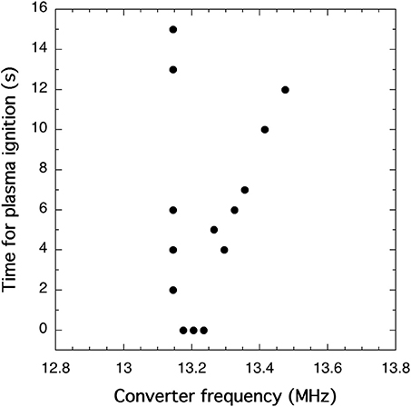
Figure 5. Time for the plasma to ignite vs. operating frequency for the IRUKANDJI atmospheric pressure test configuration of Figure 1; gas flow rate is 20 sccm and pulsed operation is at 20 kcycles yielding a constant gate current of 0.05 A. Due to the non-linearity of the Converter the power decreases from PMiniPR = 2.88 W at 13.17 MHz to 1.6 W at 13.475 MHz.
Typically for a gas flow rate of 30 sccm, the two pumping configurations of Figure 7 gives a WOMBAT chamber pressure of 2.8 × 10⁻⁴ Torr and 6.7 × 10⁻⁵, respectively, yielding effective pumping speeds of 1,250 l.s−1 and 6,000 l.s−1. For both pumping conditions, the collision mean free paths are orders of magnitude longer than the typical dimensions of the thruster where ionizing collisions take place (choked flow regime [29]) and the plasma ON/OFF frequencies are essentially independent of the pumping equipment. The Converter frequency can be affected by the argon mass flow rate injected through a small channel where it is ionized. Testing under two pumping conditions was carried out since the present Converter design includes low-cost components not specifically rated for operation in vacuum. For space use it is desirable to be able to operate the Converter for any flow rate without changing the operational frequency. This was demonstrated by the ability to generate a plasma at a selected “nominal” Converter current of 0.24 A (points in the middle exhibiting no time delay for ignition and defined as the resonant frequency of Figure 4) which correspond to a constant power into the plasma of PMiniPR ~ 0.8 × 0.24 × 20 × 0.4 ~ 1.54 W. In vacuum this frequency is about 13.4 MHz, i.e., about 0.2 MHz higher than the atmospheric testing results of Figure 4 (resonance at 13.17 MHz for CW and 20 kcycles pulsing condition), a topic for further studies. The Converter was turned on and off over 100 times before being brought back to atmospheric pressure and successfully tested again using the configuration of Figure 1. No change in its operation was detected.
Although it is beyond the scope of this study to fully quantify the thrust gain from such a pressure increase of Figure 6, a quick estimate similar to the calculations and computer simulations of Charles and Boswell [8], Fridman et al. [12], and Ho et al. [29] can be made: an argon gas flow of 20 sccm corresponds to 0.595 mg.s−1 or 0.896 × 10¹⁹ argon atoms per second. If these neutrals were being expelled from a nozzle at the sound speed (Mach 1) of (where T is the gas temperature, kB = 1.38 × 10⁻²³ J.K−1 is the Boltzmann constant, γAr = 1.667 is the specific heat capacity for argon and is the atomic mass of argon), the corresponding thrust from the momentum term (neglecting the neutral gas pressure term [12, 29]) would be mN at T ~ 300 K. Recent computer simulations [24] show that approximately one tenth of the power injected into the plasma is converted into gas heating: hence with 10 Watts into MiniPR, 1 Watt or 1 J/s of kinetic energy ϵ is effectively transferred into heating the gas: where Mt is the total argon mass ejected per second yielding for 20 sccm. Considering all three degrees of freedom for argon i.e., 3 × (1/2) then vgz = 610 m.s−1 along the thruster axis, about twice the sound speed (). The thrust gain from the plasma would be Fplasma ~ 0.17 mN yielding a total thrust of Ftotal ~ 0.36 mN. For the “nominal” power of 1.54 W of Figure 7 and a flow of 20 sccm, the total thrust would be 0.22 mN. A direct measurement of thrust values in the 0.1–1 mN range is a challenging task and computer fluid dynamics simulations are likely to be a better scenario for thrust determination with details on heat transfer via ion-neutral collisions and thermalization already reported [24]. The use of computer fluid dynamics modeling will facilitate further optimization of the plasma cavity geometry to maximize the energy transfer into gas heating.
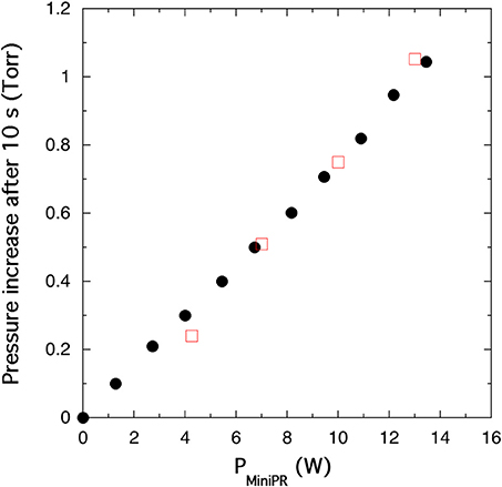
Figure 6. Plenum pressure increase after 10 s of plasma as a function of power delivered to MiniPR using system (1): Converter operating at 13.16 MHz (filled black dots with PMiniPR ~ 0.8IconvVconv) and system (2): MKS rf generator operating at 13.5 MHz (open red squares squares with PMiniPR ~ 0.5Pmks) for the IRUKANDJI atmospheric pressure test configuration of Figure 1; gas flow rate is 20 sccm.
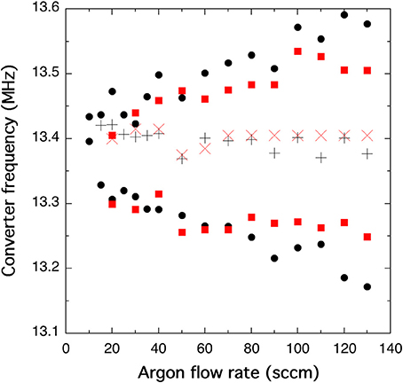
Figure 7. Ignition (lowest values), extinction (highest values) Converter frequencies measured vs. argon gas flow rate under turbo-molecular pumping (solid black dots) and cryogenic pumping (solid red squares) using the WOMBAT vacuum test configuration of Figure 2 and pulsed operation at 40 kcycles. “Nominal” frequency yielding immediate plasma striking at a constant PMiniPR value of 1.54 W for the turbo-molecular pumping case (black crosses) and cryogenic pumping case (red crosses); for the 30 sccm case the measured effective pumping speed is 1,250 and 6,000 l.s−1 for the turbo-molecular and cryogenic pumping cases, respectively; for each flow rate the sweep is performed from low to high frequency.
4. Conclusions
Gas flow heating using radio frequency plasmas offers the possibility of depositing power in the center of the flow rather than on the outside over much shorter timescales than those corresponding to electro-thermal systems limited to actively heated walls. The present study is a proof of concept of switch mode amplifier technology to power the electrothermal capacitively coupled radiofrequency Pocket Rocket thruster. The Converter power system is specifically designed to match the impedance of the plasma and obtain maximum efficiency at a designed resonant frequency. Testing showed a slight shift in that frequency between the atmospheric and vacuum testing configurations, but this shift is well within the operational envelop of the Converter. Changes in the gas flow rate or duty cycle in pulsed operation yield thrust control. Refinements to the rf and gas delivery systems are expected to improve the overall footprint and weight of the system, while maintaining low cost. Future work will aim at complete integration within a 1 “CubeSat” Unit and prediction of thrust output for various thruster geometries using computer fluid dynamics modeling.
5. Author Contributions
The thruster power supply concept was discussed by all authors. The converter prototype was designed and manufactured by Stanford University and tested as described in the manuscript at the Australian National University. All authors contributed to the data analysis and to the manuscript.
Conflict of Interest Statement
The authors declare that the research was conducted in the absence of any commercial or financial relationships that could be construed as a potential conflict of interest.
Acknowledgments
This research was partially funded by the Australian Space Research Program (WOMBAT upgrade as part of the Australian Plasma Thruster (APT) project), the Australian Research Council Discovery Project (Pocket Rocket thruster research as part of the DP140100571 project) and Lockheed Martin US (Pocket Rocket thruster Research and Development contract). The authors would like to thank the Research School of Physics and Engineering for the purchase of the AWG Siglent generator, four channel Siglent oscilloscope and rf accessories. The authors would like to thank Frontiers for financial assistance with the open access editorial fees.
References
2. Lieberman MA, Lichtenberg AJ. Principles of Plasma Discharges and Materials Processing. New York, NY: Wiley-Interscience (1994).
3. Keidar M, Zhuang T, Shashurin A, Teel G, Chiu D, Lukas J, et al. Electric propulsion for small satellites. Plasma Phys. Control Fusion (2015) 57:014005. doi: 10.1088/0741-3335/57/1/014005
4. Mazzoufre S. Electric propulsion for satellites and spacecraft: established technologies and novel approaches. Plasma Sources Sci. Technol. (2016) 25:033002. doi: 10.1088/0963-0252/25/3/033002
5. Ahedo E. Plasmas for space propulsion. Plasma Phys. Control Fusion (2011) 53:124037. doi: 10.1088/0741-3335/53/12/124037
6. Charles C. Plasmas for spacecraft propulsion. J. Phys. D. Appl. Phys. (2009) 42:163001. doi: 10.1088/0022-3727/42/16/163001
7. Lukas J, Teel G, Kolbeck J, Keidar M. High thrust-to-power ratio micro-cathode arc thruster. AIP Adv. (2016) 6:025311. doi: 10.1063/1.4942111
8. Charles C, Boswell R. Measurement and modeling of a radiofrequency micro-thruster. Plasma Sources Sci. Technol. (2012) 21:022002. doi: 10.1088/0963-0252/21/2/022002
9. Boswell RW. Plasma Micro-thruster. International Patent WO 2012151639 A1. Madison, CT: IFI CLAIMS Patent Services (2012).
10. Greig A, Charles C, Hawkins R, Boswell R. Direct measurement of neutral gas heating in a radio-frequency electrothermal plasma micro-thruster. Appl. Phys. Lett. (2013) 103:074101. doi: 10.1063/1.4818657
11. Greig A, Charles C, Paulin N, Boswell R. Volume and surface propellant heating in an electrothermal radio-frequency plasma micro-thruster. Appl. Phys. Lett. (2014) 105:054102. doi: 10.1063/1.4892656
12. Charles C, Boswell RW, Bish A, Khayms V, Scholz EF. Direct measurement of axial momentum imparted by an electrothermal radiofrequency plasma micro-thruster. Front. Phys. (2016) 4:19. doi: 10.3389/fphy.2016.00019
13. Greig A, Charles C, Boswell R. Simulation of main plasma parameters of a cylindrical asymmetric capacitively coupled plasma micro-thruster using computational fluid dynamics. Front. Phys. (2015) 2:80. doi: 10.3389/fphy.2014.00080
14. Charles C, Hawkins R, Boswell R. Particle in cell simulation of a radiofrequency plasma jet expanding in vacuum. Appl. Phys. Lett. (2015) 106:093502. doi: 10.1063/1.4914109
15. Fruchtman A. Energizing and depletion of neutrals by a collisional plasma. Plasma Sources Sci. Technol. (2008) 17:024016. doi: 10.1088/0963-0252/17/2/024016
16. Charles C, Boswell RW, Bish A. Low-weight fixed ceramic capacitor impedance matching system for an electrothermal plasma microthruster. J Propul. Power (2014) 30:1117. doi: 10.2514/1.B35119
17. Pascale A. Design and Construction of a Propellant Sub-System for SP3s CubeSat Plasma Thruster. Honours Thesis, The Australian National University (2016).
18. Charles C, Boswell RW, Takahashi K. Investigation of radiofrequency plasma sources for space travel. Plasma Phys. Control Fusion (2012) 54:124021. doi: 10.1088/0741-3335/54/12/124021
19. Charles C, Boswell RW, Bish A. Variable frequency matching to a radiofrequency source immersed in vacuum. J. Phys. D. Appl. Phys. (2013) 46:365203. doi: 10.1088/0022-3727/46/36/365203
20. Rivas JM, Han Y, Leitermann O, Sagneri AD, Perreault DJ. A high-frequency resonant inverter topology with low-voltage stress. IEEE Trans. Power Electr. (2008) 23:1759. doi: 10.1109/TPEL.2008.924616
21. Rivas J. Radio Frequency dc-dc Power Conversion. Ph.D. thesis, The Massachusetts Institute of Technology (2006).
22. Fridman G, Friedman G, Gutsol A, Shekhter AB, Vasilets VN, Fridman A. Applied plasma medicine. Plasma Process Polym. (2008) 5:503. doi: 10.1002/ppap.200700154
23. Charles C, Bish A, Boswell RW, Dedrick J, Greig A, Hawkins R, et al. A short review of experimental and computational diagnostics for radiofrequency plasma micro-thrusters. Plasma Chem. Plasma Process (2016) 36:29–44. doi: 10.1007/s11090-015-9654-5
24. Ho TS, Charles C, Boswell RW. Neutral gas heating and ion transport in a constricted plasma flow. Phys. Plasmas (2017) 24:084501. doi: 10.1063/1.4996014
25. Liang W, Raymond L, Rivas Davila J, Charles C, Boswell R. Structurally supportive RF power inverter for a CubeSat electrothermal plasma micro-thruster with PCB inductors. In: Proceedings of the 32nd Annual IEEE Applied Power Electronics Conference and Exposition, March 26-30 (2017) (Tampa, FL).
26. Liang W, Raymond L, Rivas Davila J, Boswell R, Charles C. Structurally Supportive RF Power Inverter for a CubeSat Electrothermal Plasma Micro-thruster with PCB Inductors. Provisional Patent Application Number 62/475599 (2017).
27. Liang W, Raymond L, Praglin M, Biggs D, Righetti F, Cappelli M, et al. Low-mass RF power inverter for cubeSat applications using 3-D printed inductors. IEEE J. Emerg Select Top Power Electron. (2017) 5:880. doi: 10.1109/JESTPE.2016.2644644
28. Takahashi K. Radiofrequency antenna for suppression of parasitic discharges in a helicon plasma thruster experiment. Rev. Sci. Instrum. (2012) 83:083508. doi: 10.1063/1.4748271
Keywords: thrusters, amplifiers, electronic, radiofrequency plasmas, switch mode amplifier, nano-satellite, CubeSats
Citation: Charles C, Liang W, Raymond L, Rivas-Davila J and Boswell RW (2017) Vacuum Testing of a Miniaturized Switch Mode Amplifier Powering an Electrothermal Plasma Micro-Thruster. Front. Phys. 5:36. doi: 10.3389/fphy.2017.00036
Received: 18 May 2017; Accepted: 14 August 2017;
Published: 29 August 2017.
Edited by:
Ashild Fredriksen, University of Tromsø, NorwayReviewed by:
Eugen Stamate, Technical University of Denmark, DenmarkLuis Conde, Escuela Tecnica Superior de Ingenieria Aeronautica y del Espacio (ETSIAE), Spain
Copyright © 2017 Charles, Liang, Raymond, Rivas-Davila and Boswell. This is an open-access article distributed under the terms of the Creative Commons Attribution License (CC BY). The use, distribution or reproduction in other forums is permitted, provided the original author(s) or licensor are credited and that the original publication in this journal is cited, in accordance with accepted academic practice. No use, distribution or reproduction is permitted which does not comply with these terms.
*Correspondence: Christine Charles, christine.charles@anu.edu.au