Safety of Simultaneous Scalp or Intracranial EEG during MRI: A Review
 Hassan B. Hawsawi
 David W. Carmichael
 Louis Lemieux
- 1Department of Clinical and Experimental Epilepsy, UCL Institute of Neurology, London, United Kingdom
- 2MRI Unit, Epilepsy Society, Chalfont St. Peter, United Kingdom
- 3Department of Medical Imaging, King Abdullah Medical City (KAMC), Makkah, Saudi Arabia
- 4Developmental Imaging and Biophysics Section, UCL Institute of Child Health, London, United Kingdom
Understanding the brain and its activity is one of the great challenges of modern science. Normal brain activity (cognitive processes, etc.) has been extensively studied using electroencephalography (EEG) since the 1930's, in the form of spontaneous fluctuations in rhythms, and patterns, and in a more experimentally-driven approach in the form of event-related potentials (ERPs) allowing us to relate scalp voltage waveforms to brain states and behavior. The use of EEG recorded during functional magnetic resonance imaging (EEG-fMRI) is a more recent development that has become an important tool in clinical neuroscience, for example for the study of epileptic activity. The purpose of this review is to explore the magnetic resonance imaging safety aspects specifically associated with the use of scalp EEG and other brain-implanted electrodes such as intracranial EEG electrodes when they are subjected to the MRI environment. We provide a theoretical overview of the mechanisms at play specifically associated with the presence of EEG equipment connected to the subject in the MR environment, and of the resulting health hazards. This is followed by a survey of the literature on the safety of scalp or invasive EEG-fMRI data acquisitions across field strengths, with emphasis on the practical implications for the safe application of the techniques; in particular, we attempt to summarize the findings in terms of acquisition protocols when possible.
Introduction
Electroencephalography (EEG) is a technique to record the brain's electrical activity. Since its introduction by Berger in 1929 and replication by Adrian in 1934 [1], this technique has evolved from recording electrophysiological of the brain activities to clinical use including identification of epileptic seizures, non-epileptic seizures, migraine and movement disorders based on the spontaneous changes in the rhythms and shapes of the event-related potentials (ERPs). The activity of neurons, and to a lesser extent glial cells, produces electrical and magnetic fields [2]. In epilepsy, recording patients having a seizure using scalp EEG is a clinical tool of the utmost importance especially when used in conjunction with video recording to better identify the seizure onset. Two types of EEG are available: scalp EEG, the non-invasive tool capable of recording brain activity, mostly originating in the superficial neocortex, and intracranial EEG (icEEG), an invasive technique requiring surgery with exquisite sensitivity, although more restricted to the immediate vicinity of the implanted electrodes [2–4]. According to Tao et al. [5], recognizable activity recorded on scalp EEG must originate from at least 10 cm2 of cortical area. However, volume conduction and the attenuating effect of the skull make it difficult to relate these signals to their specific origin, forcing the investigator to make assumptions on the nature of the generator, combined with models of the associated fields: this is the inverse problem of EEG (MEG) [2]. IcEEG is capable of detecting activities generated in the mesial cortex during a seizure [6, 7]. In addition, icEEG has the ability to detect weaker brain activity that sometimes cannot be identified in scalp EEG and MEG and it can only detect activity occurring within a set of small brain regions defined by patient clinical needs [2, 3].
Functional brain imaging can help to localize regions responsible for epileptic discharges; this includes positron emission tomography (PET), single photon emission computed tomography (SPECT) and functional magnetic resonance imaging (fMRI). FMRI reveals changes in the blood oxygenation level [8] by measuring the local hemodynamic variations through detecting the changes in the blood oxygen level dependent (BOLD) signals that can be seen clearly during brain activities [9]. FMRI can be used to identify regions involved in the generation of epileptic discharges, particularly when combined with EEG: Simultaneous scalp EEG-fMRI [10, 11] or icEEG-fMRI [12–17]. However, as with all simultaneous multimodal data acquisitions methodologies, data quality can be compromised due to interactions between the two systems, and the subject [18].
The potential benefits of simultaneous scalp EEG-fMRI or icEEG-fMRI are plentiful. However, there are several risks associated with the three types of magnetic fields used by MRI: the static magnetic field (B0), time-varying magnetic gradient field and radiofrequency (RF) magnetic field (B1). The greatest risk is generally heating which is related to RF electromagnetic field-induced currents that cause increased power deposition in the tissue in the vicinity of metallic EEG or icEEG electrodes when applying concurrent fMRI [19]. In addition heating can also occur as a result of the induced currents by the switching magnetic fields [20]. These problems can cause tissue burns in the locations adjacent to the metallic electrodes [20, 21].
The main objective of this review is to provide a survey of the current knowledge regarding the safety of placing EEG electrodes in contact with or within human subjects, within the MRI scanner; although our primary interest is in the use of non-invasive (scalp) and invasive EEG electrodes, we consider studies of other brain implants such as electrodes for deep brain stimulation (DBS), to the extent that studies involving those are directly relevant to the topic of this review. Specifically, depth intra-cranial EEG electrodes are very similar to DBS electrodes, geometrically and in their composition, and therefore we believe that any published work on the safety implications of placing DBS electrodes in the MRI environment must be included in this review.
The article is structured as follows: first, we briefly review the health hazards that are associated with the technique of simultaneous scalp EEG-fMRI and icEEG-fMRI after which we discuss the main theoretical aspects of EEG equipment when subjected to MRI. Second, we list the factors that can affect the increase of the heating of the scalp EEG and implanted electrodes inside the MRI that are subjects of previous and current research studies. Finally, we follow that by reviewing the appropriate acquisition protocol.
Health Hazards Related to Current Flow in, and in the Presence of Conductive Electrodes in Contact with or within, Human Tissue: A Brief Survey of Observations
Observations from the use of diathermy show that electrical currents of the order of 1 A or greater may cause skin burns around metallic electrodes; similar effects have been observed in the vicinity of electrodes in contact with tissue placed in the MR environment [22–25]. Ulcers can be caused due to electrolysis from direct currents (DC) [20, 26]. Electro-motive forces and thermal skin damage are caused at the electric field of 3,500 V/m [25, 27]. Electric shock or stimulation under the frequency of 100 KHz and tissue heating in the frequencies higher than 100 KHz occur as a result of current flow to the body in contact with a metallic objects [20, 28–31]. Human subjects reported mild neural stimulation when exposed to gradient field changes of 61 Ts−1 [32]. Other health effects of the switching gradients in the body include nerve or muscle stimulation [33–35]. Schaefer et al. estimated that nerve simulation might occur during exposure to an electric field of 0.0006 Volts/m or greater assuming the radius of the patient 0.2 m [33]. Prolonged RF induced heating for up to 5°C (over the normal body temperature) would damage the neurons [34, 36] and that depends on the sensitivity of the tissue in the brain [37, 38].
We are not aware of any officially recorded report of significant injury directly linked to EEG recording inside the MR scanner in the scientific literature, European or North American regulatory authority databases or those of equipment manufacturers (Robert Stormer, Brain Products GmbH; personal communication). However, there are reports of ECG electrode-related burns sometimes placed during EEG-fMRI recording sessions [39].
The Sources of Health Hazards in Simultaneous EEG and fMRI: Theoretical Considerations
The sources of health hazards associated with the use of EEG during MRI scanning have been studied since the technique's first published demonstrations of feasibility of recording EEG on 0.3 T MRI systems [40, 41] and then continued as EEG-fMRI was developed on 1.5 T scanners [42–48]. The same general safety considerations apply to EEG-fMRI as for all applications of MR to human subjects. In summary, safety issues might arise not only from the physical forces or from magnetic fields on these foreign objects but also inductive interactions between magnetic fields and the body and other components placed within the field [31]. In addition, capacitive interactions occur between the RF electrical field and the human body close to RF transmit coils in the form of (time varying) charge accumulation [20].
As with the introduction of any device not part of the MR system in the scanner, extra precautions are advised and careful consideration of any potential additional health hazard specifically related to the device should be given: ballistic (projectile) and electrical device safety issues and electromagnetic compatibility; these will not be the subject of this review and the reader should consult standard texts on MR safety and electrical device safety (as applied outside the MR environment), for example, [31, 49, 50]. In the case of EEG recording, we have the introduction of electrically conductive circuits consisting of powered amplifiers electrically connected to the patient via leads and electrodes attached to the patient's body and additional risks can arise from induced currents. Such electrically active components are the subject of electromagnetic compatibility regulations and standards such as produced by the International Electrotechnical Commission (IEC) (www.iec.ch), International Organization for Standardization (ISO) (www.iso.org), the US Federal Communications Commission (FCC) (www.fcc.gov) and the Society of Automotive Engineers (SAE) (www.sae.org). The conductive loops in EEG equipment typically contain high impedance components in the amplifiers and low impedance segments [20].
Let us consider the exposure of conductive to the electromagnetic fields involved in the acquisition of MR images, namely the magnetic (B) and electric (E) fields. Interactions with different types of materials arise when EEG electrodes and leads are introduced in the three types of magnetic fields used in MRI. First, the strong and uniform static magnetic field (B0) interacts with different materials that have specific magnetic properties that include: diamagnetic, paramagnetic and ferromagnetic materials, resulting in mechanical forces (the aforementioned ballistic effects) or torques. Diamagnetic materials are repelled by magnetic field forces as a result of these forces. The paramagnetic or ferromagnetic materials are attracted by the forces of the magnetic fields. Second, RF electromagnetic fields, that are produced by RF coils during the MR sequence, contains two components; one magnetic (B1), and the second non-conservative electric component [20, 51]. For a circularly polarized B1, the electrical component can be expressed as follows:
Where ω0 is the Larmor frequency (63.76 MHz and 127.7 for 1.5 T and 3 T, respectively) and ẑ is the unit vector along the scanner's long (Bo) axis. Third, the gradient magnetic fields that modulate Bz produced by the scanner's gradient coils, for spatial encoding along the 3 orthogonal axes x, y and z [52]:
Therefore, induced currents can arise in circuits comprising of conductive loops (including body tissues) when exposed to a time-varying magnetic field (gradient and RF) or when there are moving loops interacting with a spatially varying static magnetic field (B0) [19, 20]. The ERF field can give rise to time-varying charge accumulation in extended linear conductors. The currents and charges resulting from such interactions increase with the strength and frequency of the applied fields (and/or the rate of motion within the fields) and require careful consideration in theory, and possibly experimentally.
Theory of the Interaction between Closed Circuits (Loops) and the Switching Gradient Field
The interaction between conductive loops and a time-varying magnetic field follows Faraday's law:
Where V is the induced electromotive force, (dS) is the infinitesimal area parameter which is also a factor of the moving surface area (A); B is the magnetic field. Equation (3) can be generalized to show the relationship between the electric and switching magnetic fields; Maxwell-Faraday's equation:
Where ∇ is the curl operator, is the electric field and dB/dT is the rate of the magnetic field. In MRI terms, the maximum change in the magnetic field (dB/dT)max corresponds to the gradient field's (Smax) maximum slew rate at the position (z) relative to the central axis of the gradient coils:
The switching gradient field that is applied in three coordinates x, y, and z, and used to modulate the resonance frequency, is an important element of MR scanning pulse sequences. The switching gradient field can interact with conducting loops causing one main issue for EEG-fMRI: the flow of the currents within the loop of tissues that depends on (dB/dT), the conductivity of the body and the cross-section of the conducting loop [32].
Interaction between the RF Field and Circuits (Loops and Linear Antennas)
At frequencies in the MHz range and above, and in contrast to the gradient fields, the electrical component of the EM field produced by coils becomes a primary element with significant safety implications.
Concerning the magnetic element, B1, the following proportionality relationship applies the induced voltage, V, in a closed circuit:
The exact relationship is a function of the circuit's geometry and location, and B1 distribution [20]. This occurs in loop antennas (inductive coupling).
The electrical part of the RF field can generate charges to flow and accumulate in extended wires (capacitive coupling) [20] according to Equation (1) for the E field for circularly polarized B1. More generally the effect of EEG equipment can be considered as altering the electric field such that its overall power is increased both globally and in localized areas.
Interaction between Moving Closed Circuits (Loops) and Static Magnetic Field (B0)
Moving loops interaction with the static magnetic fields (B0) follows Equation (3) and the electromagnetic field and can be calculated by the following equation:
Where (dS/dt) is the average of the loop area across the static magnetic field.
Magnetic Forces and Torques
Another potential source of health hazard is the presence of magnetic forces and torques on any conductive or magnetic element because of the exposure to the temporary gradient magnetic field within the permanent magnetic fields; these forces are known as Lorentz forces that act on the icEEG implants and causes vibrations and displacement that can be directly dependent on the Bo (in the absence of the permanent magnetic parts) as well as the induced currents and the location from the iso-center of the Bo and inversely on the gradient ramp time [53–56].
In summary, the hazards related to EEG recording inside MRI fields that were listed in International Organization of Standardization [57] are:
• Heating which is induced by RF or gradient fields.
• Vibration as result of gradient switching fields.
• Force and torque due to B0.
• Extrinsic electric potential as a result of lead voltage induced by gradient fields (is not the subject of this review).
• Rectification that is caused by lead voltage induced by RF (is not the subject of this review).
• Malfunction as a result of B0, RF and gradient fields (is not the subject of this review).
Experimental Factors that can Affect the Amount of Heating in the Vicinity of Electrodes in the Application of the EEG-fMRI
In this section, we start by describing the factors that are common to the safety of all MR scanning, and taking into consideration the presence of electrodes, starting with physiological, followed by the scanning process itself and associated MR technology. We then describe factors specifically related to experiments designed to assess the safety of MR scanning in the presence of electrodes.
RF Energy Deposition
Although the type of sequence can be a general guide to RF-induced heating, the details of a MR scanning sequence are crucial in assessing the specific risks associated with its use, in the presence of conductive devices such as EEG electrodes. In the following, we discuss two common practical MR factors closely related to energy deposition: SAR and RF transmit coil type.
Specific absorption rate
The specific absorption rate (SAR) is a measure of the amount of heat generated in a body due to exposure to RF fields through the Joule effect and is the most important parameter to quantify the risks associated with RF exposure during MR scanning [19, 58]. Furthermore, it can be empirically linked to the heating of implants and electrodes [59]. SAR is the relation between tissue exposure to the RF field and the absorbed energy in a certain mass [60, 61]. SAR in units of W/Kg can be related to the electric part of the RF field, as:
Where σ is the material's electrical conductivity in (S/m), ρ is the mass density in the unit (kg/m3) and is the local RF electrical field magnitude. The SAR value can be calculated and expressed in several ways: averaged over a whole body, averaged over whole head and averaged over local or small volume that can be 1 g of tissue or 10 g of tissue or other values. (In this review, we use head-averaged SAR unless indicated otherwise) Under certain conditions, without heat dissipation, SAR can be expressed in-terms of temperature changes as follows [54]:
Where Cp is the heat capacity in unit (4,186 J/C°.Kg for water) and dT/dt is the rate of temperature change.
The international safety guidelines for MRI scanning state that the increase in the temperature of human tissues must not exceed 1°C and that the SAR value should not exceed 10 W/Kg for the local SAR (using local transmit coils) [50, 60]. For the volume transmit coils such as head or body RF coils, whole-body SAR must not exceed 2 W/Kg and the whole-head SAR must not exceed 3.2 W/Kg for the head-average over 6 min [50]. For more information about thermal damage and thresholds, please refer to Sapareto and Dewey [37] and Yarmolenko et al. [38].
Type of RF transmit coil
RF transmit coils vary greatly in geometry, size (anatomical coverage) and excitation mode, depending on the desired application and scanner design, with direct consequences for the E field distribution and power. Therefore the distribution and amount of tissue heating with or without any conductive components placed in or near the RF coil is greatly affected by the coil size and design. For example, SAR values can be decreased by careful transmit coil design [62–68]. Kangarlu and co-workers performed simulations and experiments to study the impact of coil length on localized heating at 8T, showing greater heating for longer coils [69]. In practice, the volume of the coil is an important determinant of the total power required to produce the B1 field needed for a given pulse sequence with increased power requirements being associated with a greater risk of heating. Hence multiple studies have considered the type of coil coverage (head vs. body) in the presence of EEG electrodes and leads [19, 36, 55, 70, 71]. For example, Carmichael et al. [19] in a study at 1.5T in the presence of icEEG (depths or subdural grids and strips) electrodes found that the head transmit-receive coil results in significantly less localized heating compared to the body coil. The authors conclude that body transmit coil should be avoided when icEEG electrodes are present; this finding is in line with that of others, but in contradiction with Boucousis et al. [36]. This could be explained by the different electrode and phantom configuration.
In addition, the use of multi-channel coils (such as an 8-channel system arranged in two rows positioned in the z-orientation) can help to reduce the required RF power and SAR values [64, 72–75]. Multi-transmit coils offer reduced power requirement to produce RF field and thus, a decreased SAR value [63–66, 73–78].
It is important to note that there is a complex relationship between the position of the body and the conductive components of the EEG system in relation to the RF coil and their coupling which is also field strength dependant. Therefore, generalizations are limited to the range of tested circumstances such as a particular spatial arrangement of EEG equipment tested in different RF coils.
Type of MR Sequence
The type and parameters of an MR sequence are crucial factors for temperature elevation because of the obvious link between the amount of RF power deposited in the body, the power applied and heating; this deposited power, the SAR is a fundamental parameter in MR safety [55]. For structural and functional imaging of the brain in epilepsy, sequences typically used include spin echo (SE) and derived sequences such as fast spin echo (FSE) or turbo spin echo (TSE), gradient echo (GE) sequences with or without and inversion pulse for T1 weighted imaging and echo planar imaging (EPI) for functional imaging. SE involves the application of an excitation and refocusing RF pulse (90° and 180°) however it is rarely used due to long imaging times. In FSE or TSE, a series of multiple refocusing RF pulses are applied following the excitation pulse, which is termed the echo train length. A large power is required to produce the RF B1 field for refocusing pulses (that need to approach 180°) and many are applied in a short time period (order 1 per 10 ms) that leads to high RF power levels. This then causes increases in the heating effects because of the coupling between E-field and B-field in the RF band [79]. Gradient echo sequences involve a single RF pulse followed by a gradient reversal [80], and generally have a much lower SAR than SE. In either case, the amount of heating can be controlled by changing parameters such as the flip angle and sequence repetition time (TR). EPI is a time efficient sequence where an entire image is obtained in a series of gradient echoes with differing phase encoding following a single RF pulse. This makes it typically a low RF power sequence. SE-EPI uses the same readout following an excitation and refocusing pulse which increases its SAR.
Multi-band (MB) (also known as simultaneous multi-slice) sequence is a more recent development to speed the image acquisition by the use of excitations of multiple slices simultaneously [81]. This type of technique has recently become widely used in fMRI to allow faster temporal sampling than the single-banded acquisition pulse techniques. The requirements of exciting multiple slices can lead to greater RF power requirements, especially peak power and at high multiband factors. However, there are already a number of approaches to RF pulse design to limit this power requirement (e.g., Norris PINS pulses, transmit sense) [82]. In addition, for faster sampling (shorter TRs), optimal imaging requires smaller flip angles helping to limit power requirements. Nevertheless, these sequences repose the challenge of managing heating risks when higher SAR sequences are used together with EEG recording equipment particularly for high acceleration factors and high field strength MRI scanners [83].
In the context of studies focused on identifying the set of circumstances and image acquisition parameters that allow MRI in the presence of EEG electrodes (or other implants), SE sequences are often used to assess worst-case heating [20, 55, 70], and in comparison with other, less SAR intensive and more practically relevant sequences such as GE EPI used for fMRI. The former approach has the advantage of demonstrating the potential health impact of the wrong scanning protocol being used, for example through operator error, while allowing for risk assessment of lower SAR protocols. It is crucial to note that the calculation of SAR is scanner and software specific therefore to directly compare between pulse sequences across vendors B1rms (root mean squared B1) provides a much more reliable metric independent of factors such as the RF coils used, body position or weight. SAR estimates for any given acquisition are model-based and scanner manufacturer-specific and are not designed to take any foreign body into consideration and therefore, caution is advised when using SAR in relation to the heating of implants [19].
EEG Equipment-Related Factors
Type, number and position of electrodes
The general aim of most experiments on RF-induced electrode heating has been to identify the worst case scenario, which in effect means identifying the location of greatest heating for a given electrode/subject configuration. This approach is typically in accordance with the ASTM guidelines.
The types of EEG electrodes are factors that can theoretically affect the amount of localized heating in the presence of EEG electrodes in contact with human subjects in the MRI environment. EEG electrode types include scalp and icEEG (and for the purpose of this study, DBS electrodes which are extremely similar to depth EEG electrodes). The material used for the clinical and investigative scalp EEG electrode contacts range from Ag/AgCl, Au, plastic to stainless steel, each with greatly varying magnetic and conduction properties. Invasive (icEEG) electrodes are usually made of Pt-iridium (though steel and platinum are also used) and the conductive wires made of nichrome (NiCr). At 4T, Stevens and co-workers reported no significant heating increases in three different types of scalp EEG electrodes: brass, silver, and conductive plastic of about 0.1, 0.0, and 0.1°C, respectively, when they are attached to an oil phantom without connection to the lead wires and EEG devices and without forming a resonant loop [84]. These temperature increases changed to 0.05, 0.04, and 0.06°C for the brass, silver and conductive plastic electrodes, respectively, when they were attached to an agarose phantom indicating the importance of choosing the proper phantom and electrode materials for heating measurements in the high magnetic fields [84]. Phantom composition will be explained in the following sections.
Angelone et al have found that the number of scalp EEG electrodes can affect the amount of heating using finite difference time domain (FDTD) computational simulations. In their simulations, SAR values of 0.59 W/kg without EEG and 0.77 W/kg were estimated in the skin with 124 scalp EEG electrodes at 3T [85]. The same trend was obtained for simulations at 7T where the results showed 0.29 W/kg without scalp EEGs, 0.35 W/kg with 16 electrodes, 0.41 W/kg with 31 electrodes and 0.43 W/kg with 62 electrodes [85]. However, outside the field of MR, a reduction in heating was observed experimentally when placing increased number of electrodes in the presence of GSM900 mobile phone (RF: 890–915 MHz) that depended on the location and angle of the electrode leads with respect to the RF [86]. Importantly the shielding effect of electrodes can result in a reduction in the local SAR [85, 86].
Concerning the distribution of RF-induced heating, Vasios et al studied that with the scalp EEG electrodes according to the 10–20 international systems [87]. They measured heating of 1.09°C and 6.61°C in the CZ paste position and 0.87°C and 0.97°C 5 mm from Fp1 position when placing inkCap (thin nylon grommet contacts and thin polyester film) and the standard (gold/grass) scalp EEG electrodes, respectively [87].
Intracranial electrodes used for invasive monitoring in epilepsy patients are either strips or grids of disks that are designed to reside on the cortical surface (ECoG) or penetrating cylindrical electrodes (depth electrodes). Concerning studies of heating in the presence of icEEG, comparing depth electrodes with grid electrodes, the two electrodes tend to have similar heating [36, 55]. It has been shown that icEEG electrodes implanted coronally with their terminating wires positioned posteriorly to the magnet, showed heating below the standard allowed limits (<1°C); however, these terminating wires showed increased heating when positioned anteriorly to the magnet, and excessive heating can be seen in the parasagittal implant locations at 1.5T [70]. Therefore, it is recommended to apply EPI sequences in an orthogonal approach (perpendicular to the Z-axis of the magnet) [70]. The addition of multiple and different electrodes have been studied by Carmichael and Boucousis but the total electrode number itself has not been identified as a critical factor determining heating.
Connection cables (leads) and their configuration
The conductive termination of wires can play a significant role in the amount of localized heating in the vicinity of EEG electrodes. For instance, Carmichael et al. have tested the effect of the position of the terminal cables on heating and found that when these cables were positioned in the z-axis to the magnet, they produced high temperature of about 6°C and about 2.6°C when the cables are placed close to the body toward the feet (inside the bore) [55]. Heating can elevate above the permitted limits when the wires are shorted and placed in close proximity (effectively creating a short-circuit) [19, 36, 70].
It is well established that the length of electrode leads and cables plays a vital role in determining the amount of heating due to the possibility of resonant antenna effects, as a function of the relationship between effective length and the Larmor frequency (and therefore static field strength). This effect was investigated at 1.5T by Yeung et al. who determined that wires of a length of less than 0.6 m and around 2.6–3 m result in reduced heating [88]. Assecondi et al. also tested this phenomenon at 4T, observing a difference of 1.5°C temperature increase between two cable lengths [89].
Static Field Strength (B0)
As noted above, scanner static magnetic field strength is an important factor for localized heating in itself, because the frequency of the RF is linearly related to field strength thus the power required for a given B1 amplitude is also increased and correspondingly the same pulse sequence results in higher SAR at higher field strengths. However, the higher SAR may not always result in greater heating for a given EEG system because the coupling between any conductive structure and the RF coil will depend on their respective resonant lengths. One research study that compared the heating effect on icEEG inside 1.5T and 3T MRI scanners was performed by Carmichael et al. [19] where they studied the effect of heating in three MR systems (1.5T GE, 3T GE Signa Excite and 3T Siemens TIM Trio) and found that in general the 3T MRI systems produces higher temperature elevation above the limits than 1.5T in the vicinity of metallic electrodes specifically when using structural sequences. The temperature increase also can be high even when the head transmit coil is used [55]. Another study showed that it may be possible to use the body transmit and head receive coil configuration in 3T and low SAR EPI sequences but the structural sequences such as FSE should be avoided because they produce heating above the standard limits [36].
Mullinger, Neuner and Jorge reported that using EEG cap connected with MR compatible EEG amplifier at ultrahigh field MRI scanners (7T and 9.4T) can be performed with acceptable risk under specific conditions [90–93].
Gradient Fields
The switching magnetic gradient fields can also affect the heating in the presence of metallic implants made of conducting materials [79]. The heating from the gradient switching fields can be determined by Faraday's law where the magnetic flux change produced by the scanner induces electrical eddy currents in conductive implants which is then converted to thermal energy. The magnitude of the flux change is strongly dependant on the position relative to the magnet's iso-center [20, 79]; however this effect is minimal for EEG electrodes [20, 55].
Perfusion Process in the Human Body
Blood perfusion plays a vital role in temperature regulation and therefore is a consideration in devising safety tests, at least theoretically. Blood flow carries about 50–80% of the heat in or out the body tissues [94, 95]. There are many biophysical models that have been formulated to study temperature change or regulation by perfusion. It is noteworthy that some body parts are not normally perfused such as the eye [96]. Nonetheless, everything else being equal, perfusion should result in reduced heating compared to that observed in tests performed on (passive) phantoms and can therefore be cited as a mitigating effect although difficult to quantify or validate precisely due to the possible presence of other temperature regulating processes such as conduction, convection, radiation, metabolism and evaporation [97].
Survey of the Experimental Literature on the Safety of Scalp EEG-fMRI and icEEG-fMRI
The main health-related effect that can be caused by the RF fields when scalp or intracranial EEG are within the MRI scanner during image acquisition are thermal as consequence of tissue absorption of RF energy that can be locally increased by the presence of the EEG system.
Summaries of the experimental research articles relevant to the topic can be found in Tables 1, 2. In the following, we describe some of the highlights and discuss important experimental factors for consideration when conceiving such experiments. One of the first safety studies using EEG within MRI was performed by Zhang et al. [98], where they studied the heating effect, resonant frequency and the RF power loss when placing nickel-chromium intracranial depth electrodes inside 1.5T MRI scanner. Zhang et al. found that the resonant frequency was 100 MHz and the RF power loss was −2 dB when the electrode was in air, the resonant frequency decreased to 37 MHz and the RF power loss became −19 dB when the electrode was placed inside saline solution. The RF power loss became −3 dB at the frequency of 64 MHz (1.5T), and the heating increased to 0.07°C which was measured after each SE sequence [98]. The ASTM standard specifies the use of gel phantoms since saline can lead to significantly underestimated temperature increases due to the greater heat dissipation due to convection, which may partly explain the results of Zhang et al. [98]. We also note that the temperature measurements were performed after a delay following the scanning. Lemieux et al. also performed one of the early measurements of heating effect inside 1.5T MRI scanner examining the main factors of heat induction. It was performed by designing a loop from the wires of 15 EEG electrodes fitted with current limiting resistors in a square box shape surrounding a spherical head phantom in order to assess the effect of heating and suggest the appropriate resistor which was found to be around 5.6 k ohm for the maximum allowed specific air ratio (SAR) and 13 k ohm for the minimum heating of the fitted non-ferrous carbon resistors to achieve maximum heating of less than 1°C in the resistors for the non-loop and in the electrode [20]. While current-limiting resistors have been used to reduce the heating from the currents that are induced by the gradient and RF field, some authors have found their effectiveness in limiting the heating associated with capacitive coupling (at 7T) to be doubtful [60]. Other authors such as Bonmassar and colleagues investigated the effect of MR induced heating by the addition of junction field effect transistor (JFET) in a circuit connected to the scalp EEG has been determined to produce isolated currents with less noise when it is in OFF mode [71]. The safety profile of scalp EEG have been further characterized using similar protocols and a range of different MRI protocols and clinical setups [84, 87, 89, 90, 99–102]. The summaries of the safety studies of scalp EEG in MRI are listed in Table 1.
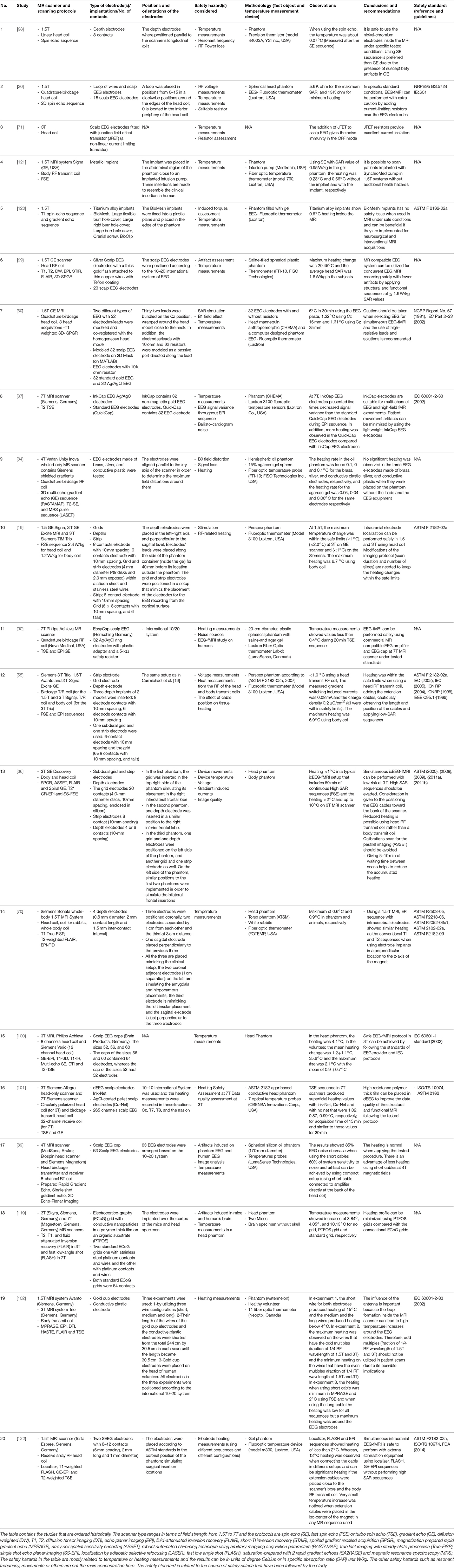
Table 1. Summaries of the experimental research of scalp or external EEG-fMRI and implanted EEG-fMRI.
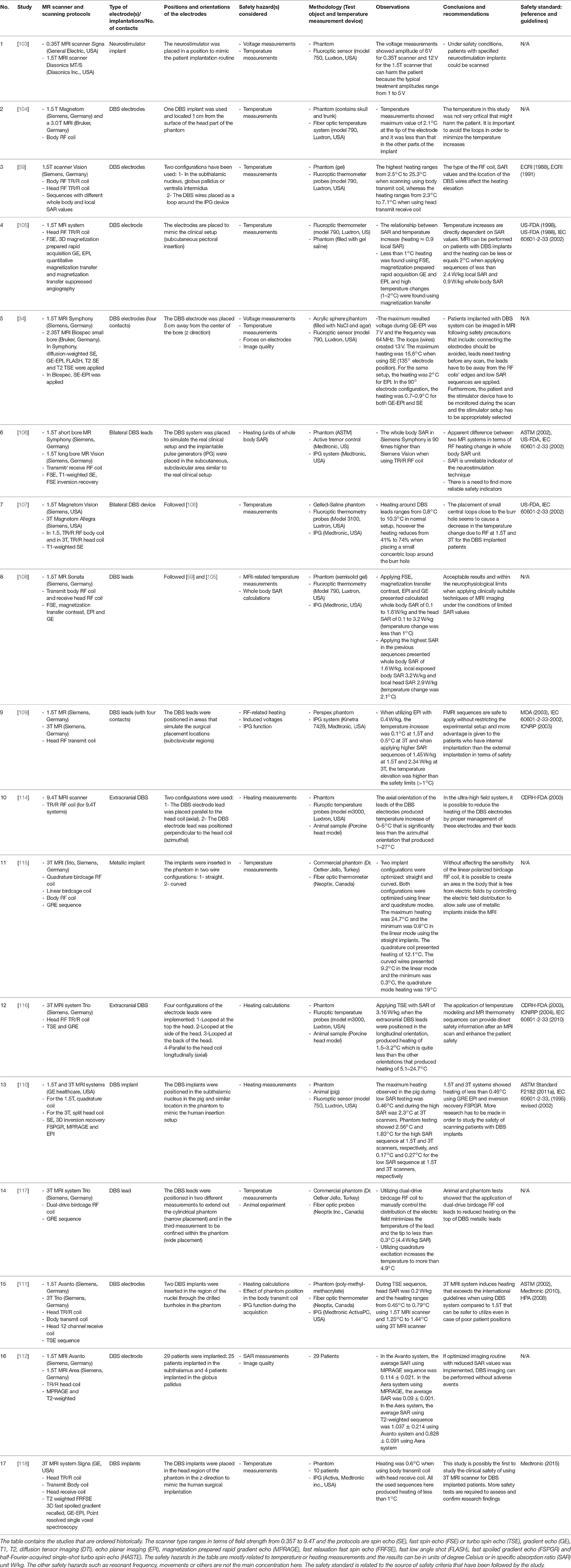
Table 2. Summaries of the experimental research of DBS external electrodes and internal implants using MRI and fMRI sequences.
In a similar vein, different groups have tested the MRI interactions with DBS devices. These typically consist of a pulse generator (housed in a metallic box), electrodes and connection wires. Overall at 0.35T [103] and 1.5T it has been found that risks can be managed under specific configurations (low SAR sequences and often a head transmit-receive coil) and the production of heating is less when DBS equipment are fully implanted [34, 59, 104–113]. In 3T MRI fields and higher [34, 59, 107, 109–111, 114–118], similar results in terms of heating have been obtained but more caution is required when dealing with DBS implants and wires as well as pulse sequences in general require greater SAR. The summaries of the safety studies of DBS external electrodes and implants in MRI are listed in Table 2.
A study by Carmichael et al focused on the safety of MRI in patients with icEEG electrodes used for epilepsy monitoring and presurgical evaluation. In this study, the mechanical forces on electrodes (types and positions), tissue heating and tissue stimulation were tested [19]. In addition, a study was performed to evaluate the safety of recording icEEG during fMRI where terminating cables positions and the use of different types of MRI scanners and RF coils were explored both on 1.5T MR scanners [55] and with the use of 3T MRI systems [19, 36, 55, 119]. In addition, studies by Shellock et al. [120], Nyenhuis et al. [121], and Bhattacharyya [122] were performed to assess the heating of metallic implants. Summaries of the safety research of icEEG and metallic implants in MRI are listed in Table 1.
Other groups [85, 93, 123, 124] have performed temperature and safety assessments when utilizing simultaneous EEG-fMRI and DBS techniques using finite difference time domain (FDTD) computing approaches. Yeung et al. performed heating assessments on conducting wires using the simulations of method of moments (MoM) [88]. Another technique known as finite element method (FEM) was used to study the heating effect on DBS electrodes and leads [125–128]. The summaries of the safety studies using computer simulation techniques when placing EEG, implants and DBS electrodes in MRI are found in Table 3. In principle, computer simulations offer the possibility of speeding up safety research by allowing the consideration of a variety of experimental scenarios (electrode configuration, subject, scanner design, sequence, etc.) the testing of which could be time consuming [85, 125]. However, this benefit is reliant on two considerations: computational speed and, most crucially, computational model accuracy. Therefore, computational simulations can be effective once the model has been subjected to exhaustive experimental validation.
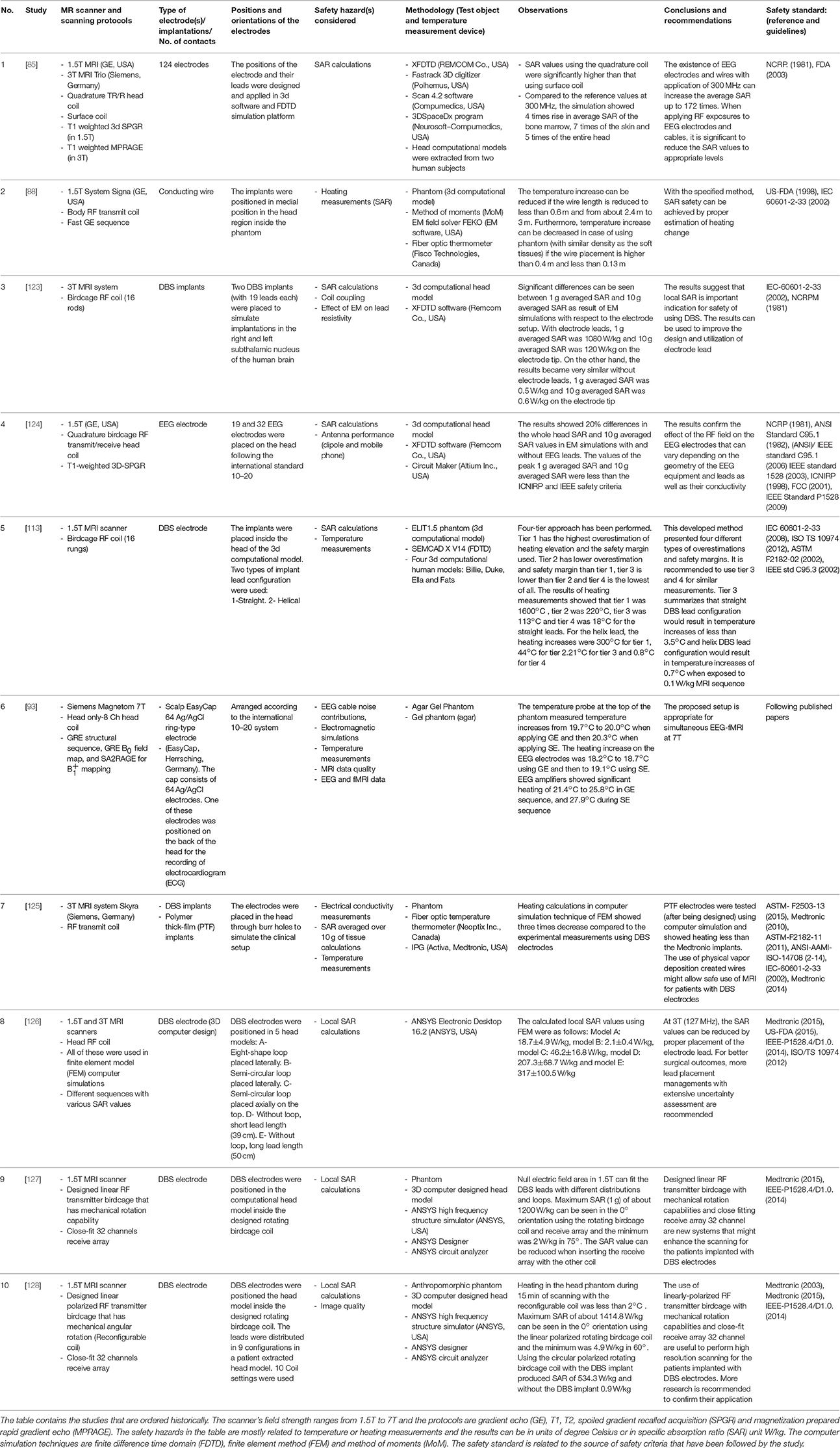
Table 3. Summaries of the researches that utilized computer simulation platforms for studying the use of EEG and DBS electrodes inside the MRI.
Animal testing in vivo was performed by Ciumas et al. [70], Gorny et al. [110], Shrivastava et al. [114], Eryaman et al. [115], Shrivastava et al. [116], Eryaman et al. [117] and showed agreement with water-gel phantom experiments. The summaries of the safety researches of EEG and implants in MRI using animal samples are included in Table 1.
In the following we describe the experimental conditions in more depth.
Phantom Composition and Geometry
ASTM has set the guidelines regarding the characteristics of phantom material for heating measurements which should have water mixed with sodium chloride and polyacrylic acid (PAA) or other materials such as hydroxyethylcellulose mixed with sodium chloride and water containing a conductivity of 0.47 ± 10% S/m at temperature range from 20 to 25°C, specific heat of 4150 J/(kg K) at 21°C, diffusivity of approximately 1.3 × 10⁻⁷ m2/s and heat capacity of about 4,150 J/kg°C in order to simulate the human thermal properties of the tissues [49]. The phantom contents and its effect on heating in the application of EEG-fMRI has been addressed by Shellock research group where they filled a rectangular plastic phantom with a semi-solid gel containing hydroxyetheyl-cellulose (HEC) and mixed with 91% of water and 0.12% of NaCl that simulates a conductivity of 0.8 S/m [120]. Other research has been performed by Mullinger et al. [91] that included mixing a heated solution of 4% Agar and 0.5% of NaCl. Boucousis et al. have used a spherical phantom filled with 45 g of semi-solid agar gel, 1500 ml of distilled water and 6.75 g NaCl, which all mixed together in the sphere and surrounded by 0.9% NaCl solution in a small area isolated from the agar solution which is also surrounded by acrylic material from the outside to produce an electrical conductivity of 0.7 S/m and simulate the electrical conductivity of the gray matter [36]. The difference in phantom materials between studies is a potential source of error for temperature measurements that are carried out inside the MRI environment. The effect of the gelling-agent PAA, which controls the viscosity of the phantom material, with the heating increase was well characterized by Park and co-workers, finding that the more viscous the phantom material the more the localized heating which might be closer to “worst case” tissues with low perfusion in the human body [129].
Location of the Temperature Probes
The location of the temperature-measuring devices relative to the EEG electrodes is another factor that affects the accuracy of temperature measurements. According to the ATSM safety standard, the temperature probes should be placed in the area which is suspected to experience the greatest heating, the temperature probe should have spatial resolution of less than 1 mm for the performance of heating calculations in all orientations [49]. Park and co-workers demonstrated the effect of taking temperature measurements on the tip of a DBS electrode, 5 mm lateral to the electrode and 5 mm above the electrode and determined different results in each setup [129]. Mattei et al. determined that there were underestimations of the measurements using Luxtron temperature probes of about 11 and 70% of the heating and SAR values, respectively at 1.5T when positioning the tip of the Luxtron temperature probe to the side of the contact and when positioning the tip of the Luxtron temperature probe to the tip of the contact [130]. The measurement of temperature and SAR values can be improved (less underestimation) by placing the active area of these particular probes (not the tip) in contact with the tip of the contact [130]. Therefore in general, care must be taken to consider the implant and probe geometry and sensitivity to ensure accurate temperature measurements are obtained.
General Conclusions in View of Minimizing the Additional Health Risks Associated with Simultaneous EEG-fMRI
It must be emphasized that the safety of EEG recording in the MR environment (or conversely, MR scanning with EEG recording equipment) should always be treated as a non-standard procedure requiring extra care, and potentially require a site-specific risk assessment, even for non-invasive (scalp EEG) and MR Conditional labeled equipment, irrespective of field strength. Once implemented, it is strongly advised to monitor the subjects throughout the procedure. These considerations are more critical for the case of MR scanning in the presence of invasive, intracranial EEG electrodes, due to the greater risk of serious injury. MRI with invasive electrodes remains a relatively rare occurrence concentrated in specialized centers with only a few relevant publications dedicated to the study of the safety aspects. Although post-icEEG (and DBS) electrode implantation MR scanning (for electrode localization validation) is an established procedure in some clinical settings, to our knowledge this is usually performed under local safety rules and supervision. As things stand it seems unlikely that the icEEG-fMRI technique with electrodes attached to recording amplifiers will become standard clinical practice in the short to medium term and will not benefit from fully tested, commercially available turn-key solutions. Therefore site- (and scanner-) specific safety investigations are warranted for all applications of MR in the presence of implanted electrodes. For field strengths above 3T, this recommendation is even stronger and also applies to scalp EEG electrodes.
Nonetheless, it is possible to extract a summary of conclusions that may guide investigators wanting to implement EEG-fMRI. Firstly, follow the instructions provided by the providers/manufacturers of the (so-called) “MR-compatible” EEG equipment (from electrode, electrode cap, etc. to amplifier/digitiser/signal transmitter) carefully; this advice usually comes in the form of a User's Manual and MR Conditional Statement and may cover the details of the application of the electrodes, EEG equipment handling and positioning, MR scanner field strength, type of MR sequence, etc. In the specific case of icEEG-fMRI, no “MR-compatible” EEG equipment solution is available on the commercial market (as of July 2017) and therefore the type of guidance described above (for scalp EEG) does not exist. Secondly, we can provide the following general guidance, for the implementation of simultaneous EEG-fMRI in every local setting:
• High-SAR MR sequences (such as FSE) should always be avoided [36, 55].
• Excessive heating is more likely to occur when using body transmit RF coils than localized (e.g., head) transmit coils [14, 19, 55].
• Noxious effects are usually reduced by placing all leads and cables along the scanner's central axis [36, 55].
At this time, given the huge variety of MR environments (scanner type and model, RF coil, etc.) it is not possible, nor wise in our opinion, to provide more specific guidelines for EEG-fMRI.
Conclusions
Simultaneous scalp EEG-fMRI remains a significant tool for the detection, identification, and localization of epileptiform discharges. Simultaneous icEEG-fMRI is a more technically challenging, and much less widely applied technique, with potential for providing richer data on brain activity. The relative complexity and constant evolution of MRI instruments, with the numerous fields involved, combined with the quasi infinite number of possible EEG electrode and wire configurations provide the setting for a range of complex potential health hazards resulting from a number of mechanisms, i.e., physical interactions such as RF-induced heating due to the aforementioned factors (including lead orientations) and therefore require careful consideration and evaluation.
Author Contributions
HH has written the initial draft of the review which was then edited, corrected and improved (addition of proper sections and updated knowledge) by DC and LL.
Conflict of Interest Statement
The authors declare that the research was conducted in the absence of any commercial or financial relationships that could be construed as a potential conflict of interest.
Acknowledgments
The authors acknowledge the excellent suggestions from the reviewers. The authors also would like to thank Dr. Robert Stoermer for the valuable contribution to this review.
References
2. Da Silva F. EEG: origin and measurement. In: Mulert C, Lemieux L, editors. EEG-fMRI: Physiological Basis, Technique and Applications. Berlin: Springer Science & Business Media (2009). p. 19–39.
3. Kaur K, Shih JJ, Krusienski DJ. Empirical models of scalp-EEG responses using non-concurrent intracranial responses. J Neural Eng. (2014) 11:035012. doi: 10.1088/1741-2560/11/3/035012
4. Enatsu R, Mikuni N. Invasive evaluations for epilepsy surgery: a review of the literature. Neurol Med Chir. (2016) 56:221–7. doi: 10.2176/nmc.ra.2015-0319
5. Tao JX, Baldwin M, Hawes-Ebersole S, Ebersole JS. Cortical substrates of scalp EEG epileptiform discharges. J Clin Neurophysiol. (2007) 24:96–100. doi: 10.1097/WNP.0b013e31803ecdaf
6. Hashiguchi K, Morioka T, Yoshida F, Miyagi Y, Nagata S, Sakata A, et al. Correlation between scalp-recorded electroencephalographic and electrocorticographic activities during ictal period. Seizure (2007) 16:238–47. doi: 10.1016/j.seizure.2006.12.010
7. Zelmann R, Lina JM, Schulze-Bonhage A, Gotman J, Jacobs J. Scalp EEG is not a blur: it can see high frequency oscillations although their generators are small. Brain Topogr. (2014) 27:683–704. doi: 10.1007/s10548-013-0321-y
8. Laufs H. A personalized history of EEG–fMRI integration. Neuroimage (2012) 62:1056–67. doi: 10.1016/j.neuroimage.2012.01.039
9. Kesavadas C, Thomas B. Clinical applications of functional MRI in epilepsy. Indian J Radiol Imaging (2008) 18:210. doi: 10.4103/0971-3026.41829
10. Cunningham CJ, Zaamout ME, Goodyear B, Federico P. Simultaneous EEG-fMRI in human epilepsy. Can J Neurol Sci. (2008) 35:420–35. doi: 10.1017/S0317167100009070
11. Vulliemoz S, Carmichael DW, Rosenkranz K, Diehl B, Rodionov R, Walker MC, et al. Simultaneous intracranial EEG and fMRI of interictal epileptic discharges in humans. Neuroimage (2011) 54:182–90. doi: 10.1016/j.neuroimage.2010.08.004
12. Vulliemoz S, Lemieux L, Daunizeau J, Michel CM, Duncan JS. The combination of EEG Source Imaging and EEG-correlated functional MRI to map epileptic networks. Epilepsia (2010) 51:491–505. doi: 10.1111/j.1528-1167.2009.02342.x
13. Goebel, R., Esposito, F. The added value of EEG-fMRI in imaging neuroscience. In: Mulert C, Lemieux L, editors. EEG-fMRI: Physiological Basis, Technique and Applications. Berlin: Springer Science & Business Media (2009). p. 19–39.
14. Carmichael DW, Vulliemoz S, Rodionov R, Thornton JS, McEvoy AW, Lemieux L. Simultaneous intracranial EEG–fMRI in humans: protocol considerations and data quality. Neuroimage (2012) 63:301–9. doi: 10.1016/j.neuroimage.2012.05.056
15. Murta T, Leite M, Carmichael DW, Figueiredo P, Lemieux L. Electrophysiological correlates of the BOLD signal for EEG-informed fMRI. Hum. Brain Mapp. (2015) 36:391–414. doi: 10.1002/hbm.22623
16. Murta T, Hu L, Tierney TM, Chaudhary UJ, Walker MC, Carmichael DW, et al. A study of the electro-haemodynamic coupling using simultaneously acquired intracranial EEG and fMRI data in humans. Neuroimage (2016) 142:371–80. doi: 10.1016/j.neuroimage.2016.08.001
17. Murta T, Chaudhary UJ, Tierney TM, Dias A, Leite M, Carmichael DW, et al. Phase–amplitude coupling and the BOLD signal: a simultaneous intracranial EEG (icEEG)-fMRI study in humans performing a finger-tapping task. Neuroimage (2017) 146:438–51. doi: 10.1016/j.neuroimage.2016.08.036
18. Villringer A, Mulert C, Lemieux L. Principles of multimodal functional imaging and data integration. In: Mulert C, Lemieux L, editors. EEG-fMRI: Physiological Basis, Technique, and Applications. Berlin: Springer Science & Business Media (2009). p. 3–17.
19. Carmichael DW, Thornton JS, Rodionov R, Thornton R, McEvoy A, Allen PJ, et al. Safety of localizing epilepsy monitoring intracranial electroencephalograph electrodes using MRI: radiofrequency-induced heating. J Magn Reson Imaging (2008) 28:1233–44. doi: 10.1002/jmri.21583
20. Lemieux L, Allen PJ, Franconi F, Symms MR, Fish DK. Recording of EEG during fMRI experiments: patient safety. Magn Reson Med. (1997) 38:943–52. doi: 10.1002/mrm.1910380614
21. Lazeyras F, Zimine I, Blanke O, Perrig SH, Seeck M. Functional MRI with simultaneous EEG recording: feasibility and application to motor and visual activation. J Magn Reson Imaging (2001) 13:943–8. doi: 10.1002/jmri.1135
22. Aigner N, Fialka C, Fritz A, Wruhs O, Zöch G. Complications in the use of diathermy. Burns (1997) 23:256–64. doi: 10.1016/S0305-4179(96)00113-1
24. Dempsey MF, Condon B. Thermal injuries associated with MRI. Clin Radiol. (2001) 56:457–65. doi: 10.1053/crad.2000.0688
25. Litvak E, Foster KR, Repacholi MH. Health and safety implications of exposure to electromagnetic fields in the frequency range 300 Hz to 10 MHz. Bioelectromagnetics (2002) 23:68–82. doi: 10.1002/bem.99
26. Smallwood RH, Barker AT, Brydon J, Pay DA, Dowd WJ. Hospital Physicists Association Topic Group Report Report 37 - Safe Design and Construction of Electromedical Equipment. The Institute of Physical Sciences in Medicine, UK (1983).
27. Welch AJ. Laser irradiation of tissue. In: Eberhart RC and Shitzer A, editors. Heat Transfer in Medicine and Biology. New York, NY: Springer. (1985). p. 135–84.
28. National Radiological Protection Board (NRPB) Board Statement on Clinical Magnetic Resonance Diagnostic Procedures. Didcot: Chilton (1991).
29. Schaefer D. Bioeffects of MRI and patient safety. In: Bronskill MJ, Sprawls P, editors. The Physics of MRI - 1992 AAPM Summer School Proceedings. Woodbury, NY: AAPM (1993).
30. Rezai AR, Baker KB, Tkach JA, Phillips M, Hrdlicka G, Sharan AD, et al. Is magnetic resonance imaging safe for patients with neurostimulation systems used for deep brain stimulation? Neurosurgery (2005) 57:1056–62. doi: 10.1227/01.NEU.0000186935.87971.2a
31. International Commission on Non-Ionizing Radiation Protection (ICNIRP). Guidelines for limiting exposure to time-varying electric and magnetic fields (1 Hz to 100 kHz). Health Physics Society (2010). 99:818–36. doi: 10.1097/HP.0b013e3181f06c86
32. Cohen MS, Weisskoff RM, Rzedzian RR, Kantor HL. Sensory stimulation by time-varying magnetic fields. Magn Reson Med. (1990) 14:409–14. doi: 10.1002/mrm.1910140226
33. Schaefer DJ, Bourland JD, Nyenhuis JA. Review of patient safety in time-varying gradient fields. J Magn Reson Imaging (2000) 12:20–9. doi: 10.1002/1522-2586(200007)12:1<20::AID-JMRI3>3.0.CO;2-Y
34. Georgi JC, Stippich C, Tronnier VM, Heiland S. Active deep brain stimulation during MRI: a feasibility study. Magn Reson Med. (2004) 51:380–8. doi: 10.1002/mrm.10699
35. Bencsik M, Bowtell R, Bowley R. Electric fields induced in the human body by time-varying magnetic field gradients in MRI: numerical calculations and correlation analysis. Phys Med Biol. (2007) 52:2337. doi: 10.1088/0031-9155/52/9/001
36. Boucousis SM, Beers CA, Cunningham CJ, Gaxiola-Valdez I, Pittman DJ, Goodyear BG, et al. Feasibility of an intracranial EEG–fMRI protocol at 3T: risk assessment and image quality. Neuroimage (2012) 63:1237–48. doi: 10.1016/j.neuroimage.2012.08.008
37. Sapareto SA, Dewey WC. Thermal dose determination in cancer therapy. Int J Radiat Oncol Biol Phys. (1984) 10:787–800.
38. Yarmolenko PS, Moon EJ, Landon C, Manzoor A, Hochman DW, Viglianti BL, et al. Thresholds for thermal damage to normal tissues: an update. Int J Hyperther. (2011) 27:320–43. doi: 10.3109/02656736.2010.534527
39. Abdel-Rehim S, Bagirathan S, Al-Benna S, O'Boyle C. Burns from ECG leads in an MRI scanner: case series and discussion of mechanisms. Ann Burns Fire Disast. (2014) 27:215–8
40. Lufkin R, Jordan S, Lylyck P, Vinuela F. MR imaging with topographic EEG electrodes in place. Am J Neuroradiol. (1988) 9:953–4.
41. Duckwiler GR, Levesque M, Wilson CL, Behnke E, Babb TL, Lufkin R. Imaging of MR-compatible intracerebral depth electrodes. Am J Neuroradiol. (1990) 11:353–4.
42. Ives JR, Warach S, Schmitt F, Edelman RR, Schomer DL. Monitoring the patient's EEG during echo planar MRI. Electroencephalogr Clin Neurophysiol. (1993) 87:417–20. doi: 10.1016/0013-4694(93)90156-P
43. Belliveau JW, Baker JR, Kwong KK, Rosen BR, George JS, Aine CJ, et al. Functional neuroimaging combining fMRI, MEG, and EEG. In: Proceedings of the International Society for Magnetic Resonance in Medicine, Vol. 1. New York, NY (1993).
44. Huang-Hellinger FR, Breiter HC, McCormack G, Cohen MS, Kwong KK, Sutton JP, et al. Simultaneous functional magnetic resonance imaging and electrophysiological recording. Hum. Brain Mapp. (1995) 3:13–23. doi: 10.1002/hbm.460030103
45. Warach S, Ives JR, Schlaug G, Patel MR, Darby DG, Thangaraj V, et al. EEG-triggered echo-planar functional MRI in epilepsy. Neurology (1996) 47:89–93. doi: 10.1212/WNL.47.1.89
46. Seeck M, Lazeyras F, Michel CM, Blanke O, Gericke CA, Ives J, et al. Non-invasive epileptic focus localization using EEG-triggered functional MRI and electromagnetic tomography. Electroencephalogr Clin Neurophysiol. (1998) 106:508–12. doi: 10.1016/S0013-4694(98)00017-0
47. Krakow K, Woermann FG, Symms MR, Allen PJ, Lemieux L, Barker GJ, et al. EEG-triggered functional MRI of interictal epileptiform activity in patients with partial seizures. Brain (1999) 122:1679–88. doi: 10.1093/brain/122.9.1679
48. Portas CM, Krakow K, Allen P, Josephs O, Armony JL, Frith CD. Auditory processing across the sleep-wake cycle: simultaneous EEG and fMRI monitoring in humans. Neuron (2000) 28:991–9. doi: 10.1016/S0896-6273(00)00169-0
49. ASTMF 2182-02a. Standard Test Method for Measurement of Radio Frequency Induced Heating Near Passive Implants during Magnetic Resonance Imaging. ASTM Committee F04 on Medical and Surgical Materials and Devices, Subcommittee F04.15 on Material Test Methods. West Conshohocken, PA: ASTM International (2007).
50. International Electrotechnical Commission (IEC) Medical Electrical Equipment—Particular Requirements for the Safety of Magnetic Resonance Equipment for Medical Diagnosis. Geneva: IEC (2010).
51. Hofman M, de Cock CC, van der Linden JC, van Rossum AC, Visser FC, Sprenger M, et al. Transesophageal cardiac pacing during magnetic resonance imaging: feasibility and safety considerations. Magn Reson Med. (1996) 35:413–22. doi: 10.1002/mrm.1910350320
52. Glover PM. Interaction of MRI field gradients with the human body. Phys Med Biol. (2009) 54:R99. doi: 10.1088/0031-9155/54/21/R01
53. Nyenhuis JA. Interactions of medical implants with the magnetic fields in MRI. In: Engineering in Medicine and Biology Society, 2003. Proceedings of the 25th Annual International Conference of the IEEE. Cancun, MX (2003). p. 3767–70.
54. Nyenhuis JA, Park SM, Kamondetdacha R, Amjad A, Shellock FG, Rezai AR MRI and implanted medical devices: basic interactions with an emphasis on heating. IEEE Trans Device Mater Reliabil. (2005) 5:467–80. doi: 10.1109/TDMR.2005.859033
55. Carmichael DW, Thornton JS, Rodionov R, Thornton R, McEvoy AW, Ordidge RJ, et al. Feasibility of simultaneous intracranial EEG-fMRI in humans: a safety study. Neuroimage (2010) 49:379–90. doi: 10.1016/j.neuroimage.2009.07.062
56. Dal Molin, R, Hecker B. Implantable medical devices MRI safe. In: Blobel B, Pharow P, Parv L, editors. PHealth 2013: Proceedings of the 10th International Conference on Wearable Micro and Nano Technologies for Personalized Health, Vol. 189. Amsterdam: IOS Press (2013). p. 96.
57. International Organization of Standardization (ISO) ISO TS 10974: Assessment of the Safety of Magnetic Resonance Imaging for Patients with an Active Implantable Medical Device. Geneva: International Organization for Standardization (2012).
58. Shellock FG. Comments on MR heating tests of critical implants. J Magn Reson Imaging (2007) 26:1182–5. doi: 10.1002/jmri.21176
59. Rezai AR, Finelli D, Nyenhuis JA, Hrdlicka G, Tkach J, Sharan A, et al. Neurostimulation systems for deep brain stimulation: in vitro evaluation of magnetic resonance imaging–related heating at 1.5 tesla. J Magn Reson Imaging (2002) 15:241–50. doi: 10.1002/jmri.10069
60. Angelone LM, Vasios CE, Wiggins G, Purdon PL, Bonmassar G. On the effect of resistive EEG electrodes and leads during 7 T MRI: simulation and temperature measurement studies. Magn Reson Imaging (2006) 24:801–12. doi: 10.1016/j.mri.2006.01.006
61. Jin J. Electromagnetic Analysis and Design in Magnetic Resonance Imaging. Boca Ranton, FL: CRC Press (1998).
62. Barth M, Breuer F, Koopmans PJ, Norris DG, Poser BA. Simultaneous multislice (SMS) imaging techniques. Magn Reson Med. (2016) 75:63–81. doi: 10.1002/mrm.25897
63. Poser BA, anderson RJ, Guerin B, Setsompop K, Deng W, Mareyam A, et al. Simultaneous multislice excitation by parallel transmission. Magn Reson Med. (2014) 71:1416–27. doi: 10.1002/mrm.24791
64. Fiedler TM, Ladd ME, Bitz AK. SAR simulations and safety. Neuroimage (in press). doi: 10.1016/j.neuroimage.2017.03.035
65. Restivo M, Raaijmakers A, van den Berg C, Luijten P, Hoogduin H. Improving peak local SAR prediction in parallel transmit using in situ S-matrix measurements. Magn Reson Med. (2017) 77:2040–7. doi: 10.1002/mrm.26261
66. Tse DHY, Wiggins CJ, and Poser BA. High-resolution gradient-recalled echo imaging at 9.4 T using 16-channel parallel transmit simultaneous multislice spokes excitations with slice-by-slice flip angle homogenization. Magn Reson Med. (2016). 78:1050–8. doi: 10.1002/mrm.26501
67. Shajan G, Kozlov M, Hoffmann J, Turner R, Scheffler K, Pohmann R. A 16-channel dual-row transmit array in combination with a 31-element receive array for human brain imaging at 9.4 T. Magn Reson Med. (2014) 71:870–9. doi: 10.1002/mrm.24726
68. Gilbert KM, Belliveau JG, Curtis AT, Gati JS, Klassen LM, Menon RS. A conformal transceive array for 7 T neuroimaging. Magn Reson Med. (2012) 67:1487–96. doi: 10.1002/mrm.23124
69. Kangarlu A, Ibrahim TS, Shellock FG. Effects of coil dimensions and field polarization on RF heating inside a head phantom. Magn Reson Imaging (2005) 23:53–60. doi: 10.1016/j.mri.2004.11.007
70. Ciumas C, Schaefers G, Bouvard S, Tailhades E, Perrin E, Comte JC, et al. A phantom and animal study of temperature changes during fMRI with intracerebral depth electrodes. Epilepsy Res. (2013) 108:57–65. doi: 10.1016/j.eplepsyres.2013.10.016
71. Bonmassar G, Anami K, Belliveau JW. Improved subject's safety in simultaneous EEG and fMRI recordings using solid state switching devices on the electrodes. In: Engineering in Medicine and Biology, 1999. 21st Annual Conference and the 1999 Annual Fall Meetring of the Biomedical Engineering Society] BMES/EMBS Conference, 1999. Proceedings of the First Joint, Vol. 2, Atlanta, GA (1999) p. 898.
72. Brink WM, Gulani V, Webb AG. Clinical applications of dual-channel transmit MRI: a review. J Magn Reson Imaging (2015) 42:855–69. doi: 10.1002/jmri.24791
73. Guérin B, Setsompop K, Ye H, Poser BA, Stenger AV, Wald LL. Design of parallel transmission pulses for simultaneous multislice with explicit control for peak power and local specific absorption rate. Magn Reson Med. (2015) 73:1946–53. doi: 10.1002/mrm.25325
74. Zhu Y. Parallel excitation with an array of transmit coils. Magn Reson. Med. (2004) 51:775–84 doi: 10.1002/mrm.20011
75. Wald LL, Adalsteinsson E. Parallel transmit technology for high field MRI. MAGNETOM Flash (2009) 40:125–35.
76. Harvey PR, Hoogeveen RM. Multi transmit parallel RF transmission technology. Koninklijke Philips Electron. (2009).
77. Katscher U. Basic and tailored RF shimming in a multi-transmit whole body MR System. PIERS Online (2008) 4:781–4. doi: 10.2529/PIERS071221114101
78. Sengupta S, Roebroeck A, Kemper VG, Poser BA, Zimmermann J, Goebel R, et al. A specialized multi-transmit head coil for high resolution fMRI of the human visual cortex at 7T. PLoS ONE (2016) 11:e0165418. doi: 10.1371/journal.pone.0165418
79. Graf H, Steidle G, Schick F. Heating of metallic implants and instruments induced by gradient switching in a 1.5-Tesla whole-body unit. J Magn. Reson. Imaging (2007) 26:1328–33. doi: 10.1002/jmri.21157
80. Elster AD. Gradient-echo MR imaging: techniques and acronyms. Radiology (1993) 186:1–8. doi: 10.1148/radiology.186.1.8416546
81. Larkman DJ, Hajnal JV, Herlihy AH, Coutts GA, Young IR, Ehnholm G. Use of multicoil arrays for separation of signal from multiple slices simultaneously excited. J. Magn. Reson. Imaging (2001) 13:313–7. doi: 10.1002/1522-2586(200102)13:2<313::AID-JMRI1045>3.0.CO;2-W
82. Feinberg DA, Setsompop K. Ultra-fast MRI of the human brain with simultaneous multi-slice imaging. J Magn Reson. (2013) 229:90–100. doi: 10.1016/j.jmr.2013.02.002
83. Auerbach EJ, Xu J, Yacoub E, Moeller S, Uğurbil K. Multiband accelerated spin-echo echo planar imaging with reduced peak RF power using time-shifted RF pulses. Magn Reson Med. (2013) 69:1261–7. doi: 10.1002/mrm.24719
84. Stevens TK, Ives JR, Klassen LM, Bartha, R. MR compatibility of EEG scalp electrodes at 4 Tesla. J Magn Reson Imaging (2007) 25:872–7. doi: 10.1002/jmri.20872
85. Angelone LM, Potthast A, Segonne F, Iwaki S, Belliveau JW, Bonmassar G. Metallic electrodes and leads in simultaneous EEG-MRI: specific absorption rate (SAR) simulation studies. Bioelectromagnetics (2004) 25:285–95. doi: 10.1002/bem.10198
86. Hamblin DL, anderson V, McIntosh RL, McKenzie RJ, Wood AW, Iskra S, et al. EEG electrode caps can reduce SAR induced in the head by GSM900 mobile phones. IEEE Trans Biomed Eng. (2007) 54:914–20. doi: 10.1109/TBME.2007.893486
87. Vasios CE, Angelone LM, Purdon PL, Ahveninen J, Belliveau JW, Bonmassar G. EEG/(f) MRI measurements at 7 Tesla using a new EEG cap (“InkCap”). Neuroimage (2006) 33:1082–92. doi: 10.1016/j.neuroimage.2006.07.038
88. Yeung CJ, Karmarkar P, McVeigh ER. Minimizing RF heating of conducting wires in MRI. Magn Reson Med. (2007) 58:1028–34. doi: 10.1002/mrm.21410
89. Assecondi S, Lavallee C, Ferrari P, Jovicich J Length matters: improved high field EEG–fMRI recordings using shorter EEG cables. J Neurosci Methods (2016) 269:74–87. doi: 10.1016/j.jneumeth.2016.05.014
90. Mullinger K, Brookes M, Stevenson C, Morgan P, Bowtell R. Exploring the feasibility of simultaneous electroencephalography/functional magnetic resonance imaging at 7 T. Magn Reson Imaging (2008) 26:968–77. doi: 10.1016/j.mri.2008.02.014
91. Mullinger K, Debener S, Coxon R, Bowtell R. Effects of simultaneous EEG recording on MRI data quality at 1.5, 3 and 7 tesla. Int J Psychophys. (2008) 67:178–88. doi: 10.1016/j.ijpsycho.2007.06.008
92. Neuner I, Warbrick T, Arrubla J, Felder J, Celik A, Reske M, et al. EEG acquisition in ultra-high static magnetic fields up to 9.4 T. Neuroimage (2013) 68:214–20. doi: 10.1016/j.neuroimage.2012.11.064
93. Jorge J, Grouiller F, Ipek Ö, Stoermer R, Michel CM, Figueiredo P, et al. Simultaneous EEG–fMRI at ultra-high field: artifact prevention and safety assessment. Neuroimage (2015) 105:132–44. doi: 10.1016/j.neuroimage.2014.10.055
94. Acharya S, Gurung DB, Saxena VP. Transient temperature distribution in human males and females body due to variation in perfusion effect. Int J Appl Math. (2014) 29:1263–70.
95. Acharya S, Gurung DB, Saxena VP. Human males and females body thermoregulation: perfusion effect analysis. J Ther Biol. (2014) 45:30–6. doi: 10.1016/j.jtherbio.2014.07.006
96. Athey T. A model of the temperature rise in the head due to magnetic resonance imaging procedures. Magn Reson Med. (1989) 9:177–84. doi: 10.1002/mrm.1910090204
97. Gokul KC, Gurung DB, Adhikary PR. Effect of blood perfusion and metabolism in temperature distribution in human eye. Adv Appl Math Biosci. (2013) 4:13–23.
98. Zhang J, Wilson CL, Levesque MF, Behnke EJ, Lufkin RB. Temperature changes in nickel-chromium intracranial depth electrodes during MR scanning. Am J Neuroradiol. (1993) 14:497–500.
99. Mirsattari SM, Lee DH, Jones D, Bihari F, Ives JR. MRI compatible EEG electrode system for routine use in the epilepsy monitoring unit and intensive care unit. Clin. Neurophysiol. (2004) 115:2175–80. doi: 10.1016/j.clinph.2004.04.011
100. Kuusela L, Turunen S, Valanne L, Sipilä O. Safety in simultaneous EEG-fMRI at 3 T: temperature measurements. Acta Radiol. (2015) 56:739–45. doi: 10.1177/0284185114536385
101. Poulsen C, Wakeman DG, Atefi SR, Luu P, Konyn A, Bonmassar G. Polymer thick film technology for improved simultaneous dEEG/MRI recording: safety and MRI data quality. Magn Reson Med. (2016). 77:895–903. doi: 10.1002/mrm.26116
102. Balasubramanian M, Wells WM, Ives JR, Britz P, Mulkern RV, Orbach DB. RF heating of gold cup and conductive plastic electrodes during simultaneous EEG and MRI. Neurodiagn J. (2017) 57:69–83. doi: 10.1080/21646821.2017.1256722
103. Gleason CA, Kaula NF, Hricak H, Schmidt RA, Tanagho EA. The effect of magnetic resonance imagers on implanted neurostimulators. Pacing Clin Electrophysiol. (1992) 15:81–94. doi: 10.1111/j.1540-8159.1992.tb02904.x
104. Kainz W, Neubauer G, Überbacher R, Alesch F, Chan DD. Temperature measurement on neurological pulse generators during MR scans. Biomed Eng Online (2002) 1:2. doi: 10.1186/1475-925X-1-2
105. Finelli DA, Rezai AR, Ruggieri PM, Tkach JA, Nyenhuis JA, Hrdlicka G, et al. MR imaging-related heating of deep brain stimulation electrodes: in vitro study. Am J Neuroradiol. (2002) 23:1795–802.
106. Baker KB, Tkach JA, Nyenhuis JA, Phillips M, Shellock FG, Gonzalez-Martinez J, et al. Evaluation of specific absorption rate as a dosimeter of MRI-related implant heating. J Magn Reson Imaging (2004) 20:315–20. doi: 10.1002/jmri.20103
107. Baker KB, Tkach J, Hall JD, Nyenhuis JA, Shellock FG, Rezai AR. Reduction of magnetic resonance imaging-related heating in deep brain stimulation leads using a lead management device. Neurosurgery (2005) 57:392–7. doi: 10.1227/01.NEU.0000176877.26994.0C
108. Bhidayasiri R, Bronstein JM, Sinha S, Krahl SE, Ahn S, Behnke EJ, et al. Bilateral neurostimulation systems used for deep brain stimulation: in vitro study of MRI-related heating at 1.5 T and implications for clinical imaging of the brain. Magn Reson Imaging (2005) 23:549–55. doi: 10.1016/j.mri.2005.02.007
109. Carmichael DW, Pinto S, Limousin-Dowsey P, Thobois S, Allen PJ, Lemieux L, et al. Functional MRI with active, fully implanted, deep brain stimulation systems: safety and experimental confounds. Neuroimage (2007) 37:508–17. doi: 10.1016/j.neuroimage.2007.04.058
110. Gorny KR, Presti MF, Goerss SJ, Hwang SC, Jang DP, Kim I, et al. Measurements of RF heating during 3.0-T MRI of a pig implanted with deep brain stimulator. Magn Reson Imaging (2013) 31:783–8. doi: 10.1016/j.mri.2012.11.005
111. Kahan J, Papadaki A, White M, Mancini L, Yousry T, Zrinzo L, et al. The safety of using body-transmit MRI in patients with implanted deep brain stimulation devices. PLoS ONE (2015) 10:e0129077. doi: 10.1371/journal.pone.0129077
112. Franceschi AM, Wiggins GC, Mogilner AY, Shepherd T, Chung S, Lui YW. Optimized minimal specific absorption rate MRI for high-resolution imaging in patients with implanted deep brain stimulation electrodes. Am J Neuroradiol. (2016) 37:1996–2000. doi: 10.3174/ajnr.A4865
113. Cabot E, Lloyd T, Christ A, Kainz W, Douglas M, Stenzel G, et al. Evaluation of the RF heating of a generic deep brain stimulator exposed in 1.5 T magnetic resonance scanners. Bioelectromagnetics (2013) 34:104–13. doi: 10.1002/bem.21745
114. Shrivastava D, Abosch A, Hanson T, Tian J, Gupte A, Iaizzo PA, et al. Effect of the extracranial deep brain stimulation lead on radiofrequency heating at 9.4 Tesla (400.2 MHz). J Magn Reson Imaging (2010) 32:600–7. doi: 10.1002/jmri.22292
115. Eryaman Y, Akin B, Atalar E. Reduction of implant RF heating through modification of transmit coil electric field. Magn Reson Med (2011) 65:1305–13. doi: 10.1002/mrm.22724
116. Shrivastava D, Abosch A, Hughes J, Goerke U, DelaBarre L, Visaria R, et al. Heating induced near deep brain stimulation lead electrodes during magnetic resonance imaging with a 3 T transceive volume head coil. Phys Med Biol. (2012) 57:5651. doi: 10.1088/0031-9155/57/17/5651
117. Eryaman Y, Turk EA, Oto C, Algin O, Atalar E. Reduction of the radiofrequency heating of metallic devices using a dual-drive birdcage coil. Magn Reson Med. (2013) 69:845–52. doi: 10.1002/mrm.24316
118. Sammartino F, Krishna V, Sankar T, Fisico J, Kalia SK, Hodaie M, et al. 3-Tesla MRI in patients with fully implanted deep brain stimulation devices: a preliminary study in 10 patients. J Neurosurg. (2016) doi: 10.3171/2016.9.JNS16908. [Epub ahead of print].
119. Ahmadi E, Katnani HA, Daftari Besheli L, Gu Q, Atefi R, Villeneuve MY, et al. An Electrocorticography grid with conductive nanoparticles in a polymer thick film on an organic substrate improves CT and MR imaging. Radiology (2016) 280:595–601. doi: 10.1148/radiol.2016142529
120. Shellock FG. Metallic neurosurgical implants: evaluation of magnetic field interactions, heating, and artifacts at 1.5-Tesla. J Magn Reson Imaging (2001) 14:295–9. doi: 10.1002/jmri.1185
121. Nyenhuis JA, Kildishev AV, Bourland JD, Foster KS, Graber G, Athey TW. Heating near implanted medical devices by the MRI RF-magnetic field. IEEE Trans Magn. (1999) 35:4133–5. doi: 10.1109/20.800779
122. Bhattacharyya PK, Mullin J, Lee BS, Gonzalez-Martinez JA, Jones SE. Safety of externally stimulated intracranial electrodes during functional MRI at 1.5 T. Magn Reson. Imaging (2017) 38:182–8. doi: 10.1016/j.mri.2017.01.012
123. Angelone LM, Ahveninen J, Belliveau JW, Bonmassar G. Analysis of the role of lead resistivity in specific absorption rate for deep brain stimulator leads at 3T MRI. IEEE Trans Med Imaging (2010) 29:1029–38. doi: 10.1109/TMI.2010.2040624
124. Angelone LM, Bit-Babik G, Chou CK. Computational electromagnetic analysis in a human head model with EEG electrodes and leads exposed to RF-field sources at 915 MHz and 1748 MHz. Radiat Res. (2010) 174:91–100. doi: 10.1667/RR1933.1
125. Serano P, Angelone LM, Katnani H, Eskandar E, Bonmassar G. A novel brain stimulation technology provides compatibility with MRI. Sci. Rep. (2015) 5:9805. doi: 10.1038/srep09805
126. Golestanirad L, Angelone LM, Iacono MI, Katnani H, Wald LL, Bonmassar G. Local SAR near deep brain stimulation (DBS) electrodes at 64 and 127 MHz: a simulation study of the effect of extracranial loops. Magn Reson. Med. (2016). 78:1558–65. doi: 10.1002/mrm.26535
127. Golestanirad L, Keil B, Angelone LM, Bonmassar G, Mareyam A, Wald LL. Feasibility of using linearly polarized rotating birdcage transmitters and close-fitting receive arrays in MRI to reduce SAR in the vicinity of deep brain simulation implants. Magn Reson Med. (2016). 77:1701–12. doi: 10.1002/mrm.26220
128. Golestanirad L, Iacono MI, Keil B, Angelone LM, Bonmassar G, Fox MD, et al. Construction and modeling of a reconfigurable MRI coil for lowering SAR in patients with deep brain stimulation implants. Neuroimage (2017) 147:577–88. doi: 10.1016/j.neuroimage.2016.12.056
129. Park SM, Nyenhuis JA, Smith CD, Lim EJ, Foster KS, Baker KB, et al. Gelled versus nongelled phantom material for measurement of MRI-induced temperature increases with bioimplants. IEEE Trans Magn. (2003) 39:3367–71. doi: 10.1109/TMAG.2003.816259
130. Mattei E, Calcagnini G, Triventi M, Censi F, Bartolini P, Kainz W, et al. MRI induced heating of pacemaker leads: effect of temperature probe positioning and pacemaker placement on lead tip heating and local SAR. In: Engineering in Medicine and Biology Society, 2006. EMBS'06. 28th Annual International Conference of the IEEE. New York, NY (2006). p. 1889–92.
Keywords: radiofrequency safety, gradient safety, thermal injury, MR safety, electroencephalography, implanted electrodes, epilepsy, neuroscience
Citation: Hawsawi HB, Carmichael DW and Lemieux L (2017) Safety of Simultaneous Scalp or Intracranial EEG during MRI: A Review. Front. Phys. 5:42. doi: 10.3389/fphy.2017.00042
Received: 17 May 2017; Accepted: 04 September 2017;
Published: 10 October 2017.
Edited by:
Federico Giove, Centro Fermi, ItalyReviewed by:
Leonardo Angelone, United States Food and Drug Administration, United StatesWim Van Paesschen, University Hospitals Leuven, Belgium
Copyright © 2017 Hawsawi, Carmichael and Lemieux. This is an open-access article distributed under the terms of the Creative Commons Attribution License (CC BY). The use, distribution or reproduction in other forums is permitted, provided the original author(s) or licensor are credited and that the original publication in this journal is cited, in accordance with accepted academic practice. No use, distribution or reproduction is permitted which does not comply with these terms.
*Correspondence: Hassan B. Hawsawi, hassan.hawsawi.15@ucl.ac.uk