Utilization of human-like pelvic rotation for running robot
 Takuya Otani1,2*
 Kenji Hashimoto3,4
 Masaaki Yahara5
Shunsuke Miyamae5
Takaya Isomichi5
Shintaro Hanawa6
Masaaki Yahara5
Shunsuke Miyamae5
Takaya Isomichi5
Shintaro Hanawa6
 Masanori Sakaguchi6,7
Yasuo Kawakami6
Hun-ok Lim4,8
Atsuo Takanishi4,9
Masanori Sakaguchi6,7
Yasuo Kawakami6
Hun-ok Lim4,8
Atsuo Takanishi4,9
- 1Graduate School of Advanced Science and Engineering, Waseda University, Tokyo, Japan
- 2Japan Society for the Promotion of Science, Tokyo, Japan
- 3Waseda Institute for Advanced Study, Tokyo, Japan
- 4Humanoid Robotics Institute (HRI), Waseda University, Tokyo, Japan
- 5Graduate School of Creative Science and Engineering, Waseda University, Tokyo, Japan
- 6Faculty of Sport Sciences, Waseda University, Tokyo, Japan
- 7Faculty of Kinesiology, University of Calgary, Calgary, AB, Canada
- 8Faculty of Engineering, Kanagawa University, Yokohama, Japan
- 9Department of Modern Mechanical Engineering, Waseda University, Tokyo, Japan
The spring loaded inverted pendulum is used to model human running. It is based on a characteristic feature of human running, in which the linear-spring-like motion of the standing leg is produced by the joint stiffness of the knee and ankle. Although this model is widely used in robotics, it does not include human-like pelvic motion. In this study, we show that the pelvis actually contributes to the increase in jumping force and absorption of landing impact. On the basis of this finding, we propose a new model, spring loaded inverted pendulum with pelvis, to improve running in humanoid robots. The model is composed of a body mass, a pelvis, and leg springs, and, it can control its springs while running by use of pelvic movement in the frontal plane. To achieve running motions, we developed a running control system that includes a pelvic oscillation controller to attain control over jumping power and a landing placement controller to adjust the running speed. We also developed a new running robot by using the SLIP2 model and performed hopping and running experiments to evaluate the model. The developed robot could accomplish hopping motions only by pelvic movement. The results also established that the difference between the pelvic rotational phase and the oscillation phase of the vertical mass displacement affects the jumping force. In addition, the robot demonstrated the ability to run with a foot placement controller depending on the reference running speed.
Introduction
To realize human motions, researchers performed motion capture experiments or simulations. In motion capture experiments, researchers collect and analyze data, and on the basis of the results, verify or refute their hypothesis to clarify the mechanisms of human motion. However, for ethical reasons, motions that pose a risk of injury for human subjects cannot be tested, despite the possibility of improving those motions by coordinated training (World Medical Association, 1964). Some investigators have used simulations to evaluate their models or hypotheses of human motion. However, simulations have problems such as long processing time or model error (Rose and Gamble, 2005). To resolve these problems, we have sought to conduct research on human motion and sport science by using a biped humanoid robot that can mimic human motions. When such a humanoid robot realizes human-like motion or uses an instrument as does a human, its human-like motions can be compared with those that do not mimic human motions. By using the humanoid robot, we can measure various data as joint’s angle, angular velocity, torque, robot’s attitude, and so on. For example, the risk of injury can be evaluated according to the joint’s torque. This comparison should be useful for verifying the characteristics of human motions and testing instruments, which in turn should improve the performance characteristics of both humans and robots.
We previously developed a biped humanoid robot named WABIAN-2R to mimic human motions and their underlying mechanisms (Ogura et al., 2006). WABIAN-2R, which is equipped with a 2-degree-of-freedom (DOF: roll, yaw) pelvis, shows a human-like gait with a stretched knee (Hashimoto et al., 2013, 2014). However, this robot is limited to walking. In human running, the joints of the standing leg require about 1000 W (Dalleau et al., 1998), which is much higher than the power of the actuator in WABIAN-2R.
In previous studies, running has been realized in a number of robots. Raibert et al. developed running robots with a linear spring leg (Raibert, 1986). Hyon et al. developed a biologically inspired biped robot based on a model of a dog’s leg (Hyon et al., 2003). These robots are not human-like. However, a few recent studies have shown that biped humanoid robots can run. For example, ASIMO can run at a speed of 2.5 m/s (Honda Motor Company Ltd.; Takenaka et al., 2011). Furthermore, Toyota’s biped humanoid robot can also run, using a zero moment point (ZMP)-based running control system (Tajima et al., 2009). The athlete robot developed by Niiyama et al. has a human-like musculoskeletal system built to achieve dynamic motions such as running (Niiyama et al., 2012). The biped robot MABEL, which has leg elasticity that originates from a leaf spring, can run the fastest among all presently available biped robots, attaining a speed of 3 m/s with axial constraints on the Y-axis (Grizzle et al., 2009). However, none of these robots mimic human running characteristics.
A number of important characteristics of human running have been identified by researchers in the field of biomechanics and sports science, including head stabilization (Pozzo et al., 1990), moment compensation using the upper body and arms (Collins et al., 2009), and leg stiffness (Gunther and Blickhan, 2002). However, a potentially important but as yet unreported characteristic is that a human’s pelvic movement in the frontal plane increases takeoff forces and absorbs landing impacts. In this paper, we provide evidence for this characteristic by an analysis of human motion. We then propose a running model that combines the traditional spring loaded inverted pendulum (SLIP) model (Chapman and Caldwell, 1983; Blickhan, 1989; McMahon and Cheng, 1990) and a pelvis. The proposed model, called spring loaded inverted pendulum with pelvis (SLIP2), is composed of a body mass, a pelvis, and leg springs. We then describe a running control system composed of a pelvic oscillation controller to attain control over jumping power, and a foot placement controller to adjust the running speed, and a running robot that uses the SLIP2 model, with which we successfully conducted a hopping and running experiment.
The remainder of the paper is organized as follows. In Section “Introduction,” we analyze human pelvic movement and describe the running control method, which includes control of pelvic movement and foot placement. In Section “Materials and Methods,” we describe the design of the running robot used in this study. In Section “Results,” we present and discuss experimental results. Finally, in Section “Conclusions and Future Work,” we present the conclusions and future work.
Materials and Methods
Pelvic Movement Analysis
To identify characteristics of human running motion that could be useful for designing a robot, we conducted a series of motion capture experiments with human subjects. A motion capture system with eight infrared cameras (Motion Analysis Corp., Santa Rosa, CA, USA) was used to determine three-dimensional marker positions at 240 Hz. The spherical retro-reflective markers were attached on the skin of the pelvis, thigh, shank, and rearfoot. Ground reaction forces were simultaneously collected at 2400 Hz using a force plate (Bertec Corp., Columbus, OH, USA) for the identification of the stance phase. We asked seven subjects (gender: male, height: 1724 ± 36 mm, weight: 64 ± 6 kg) to perform regular running motion at 3.5 m/s and collected five sets of data for each subject. None of the participants had any muscular, neurological, or joint disorders that could affect their performance. The study was approved by the Office of Research Ethics at Waseda University and written informed consent was obtained from all participants. These subjects were given several practice trials to ensure that they could land with a natural running style on the force plate. When the running speed was within 5% of the target speed and the subject could land on the force plate, data collection began.
Figure 1 shows the pelvic movement in the frontal plane during running. The pelvis levels off at an angle of 0°. The measurements show that the angle of the pelvis is 0.7° at heel strike, at which point the idling leg is lowered. The pelvis then rotates up to 3.0° until landing of the sole. Subsequently, the pelvis rotates in the opposite direction up to −5.3° until takeoff using the toe. After takeoff, the pelvis rotates to the initial angle for landing with the other leg, i.e., it rotates to lower the idling leg and then rotates in the opposite direction to raise it.
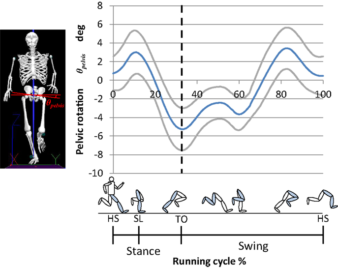
Figure 1. Human pelvic rotation in the frontal plane during running. To compare the time course changes in joint angles between trials and among subjects, the time-series data were time normalized to 101 data points, with each time interval representing 1% of the stance phase (mean, solid blue line; SD, solid gray line). First, at heel strike, the angle of the pelvis is 0.7°. Then, the pelvis rotates up to 3.0° until landing of the sole. Subsequently, the pelvis rotates in the opposite direction up to −5.3° until takeoff using the toe. After takeoff, the pelvis rotates to the initial angle for landing with the other leg. HS, heel strike; SL, sole landing; TO, toe off.
The pelvic movement during the stance phase resembles a sine wave. Usually, the vertical movement of the center of mass during human running is modeled as a SLIP. We calculated the characteristic oscillation period of the vertical movement of the center of mass from data on the ground reaction force and vertical movement of the center of mass, as well as that of the pelvic movement, by measuring the period of peak-to-peak movement. The characteristic oscillation period of the vertical movement of the center of mass was 0.29 ± 0.03 s, and that of the pelvic movement was 0.30 ± 0.03 s. Given the similarity of these values, pelvic movement will affect movement of the center of mass effectively. This result suggests that the pelvic movement in the frontal plane, which acts as sine wave, increases the takeoff force and absorbs the landing impact. The pelvic movement at landing absorbs the landing impact, and the subsequent movement increases the takeoff force.
SLIP2 Model
In previous studies, human running was modeled by a SLIP (McMahon and Cheng, 1990), whereas human walking was modeled by an inverted pendulum (Kajita and Espiau, 2008). The SLIP model is composed of a body mass and a spring leg and is based on the linear relationship between the ground reaction force and the vertical displacement of the body during running (Chapman and Caldwell, 1983; Blickhan, 1989; McMahon and Cheng, 1990). Moreover, the knee and ankle joints of the standing leg act like torsion springs that give rise to leg stiffness (Gunther and Blickhan, 2002), which along with joint stiffness vary with the running speed (Farley and González, 1996). In this model, movement in the flight phase is modeled as a parabolic motion of a mass point. With this model, which describes human running in a simple and straightforward way, the motion of the human leg in the stance phase of running stores energy and releases it like a spring. However, the SLIP model differs from the actual human body because it does not take the pelvis into account.
On the basis of the human motion analysis presented in the previous section, we propose a new model, SLIP2 (Figure 2), which is composed of an upper body, a pelvis, and spring legs. During stance, human motion is modeled by SLIP2, whereas during flight, it is modeled as a parabola. According to the SLIP2 model, running is realized by two component processes: attaining sufficient jumping power, and controlling the running speed. To realize running, we implemented a pelvic oscillation controller for attaining jumping power and a foot placement controller for controlling the running speed.
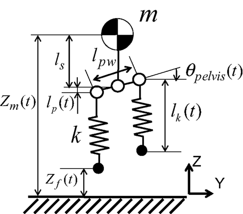
Figure 2. Spring-mass model with pelvis joint (SLIP2). The model is composed of a body mass, a pelvis, and spring legs.
Pelvic Oscillation Control
The pelvic oscillation control method is used for storing energy. In this method, the pelvis is controlled by using the natural frequency calculated from the mass weight and leg stiffness in the stance phase, and controlled to move it to the landing joint angles of pelvis in the flight phase, with the objective of attaining sufficient jumping power. The hip roll axis is controlled to be aligned with the pelvis roll axis. In the stance phase, the model, which has elastic elements, can store and release the energy by resonance. The pelvic movement is modeled as a linear displacement, and the equation of motion in the vertical direction in the stance phase is given by:
where m is the weight of the body mass; zm(t), the vertical displacement of the mass; ls, the distance between the body mass and the pelvis; lp(t), the vertical displacement of the pelvis caused by its rotation; lk(t), the length of the leg spring; k, the leg stiffness; g, the gravitational acceleration (= 9.8 m/s2); and t,the time of the stance phase.
Based on the human motion analysis, the pelvic movement in the stance phase is expressed as follows:
where A is the pelvic rotation amplitude; ω, the natural frequency; tstance, the time of the stance phase; and ϕ, the phase difference between the mass vertical movement and the pelvic movement.
To use the resonance effectively, the phase difference between the mass vertical movement and the pelvic movement in the stance phase is important. To analyze the effect of the pelvic movement, we calculated the mass vertical movement of the SLIP2 model. At first, the SLIP2 model fell from the mass height; 0.9 m. After landing, the SLIP2 model moved its pelvis according to the above equation.
We performed on the three conditions that: the pelvic rotation amplitude was 0°, the phase difference was 0 rad or π rad for verifying the influence of the phase difference. In this calculation, we set the mass 55 kg, the leg stiffness 16 kN/m, and the pelvic rotation amplitude 0° or 5°. Figure 3 shows the mass height of the body in this calculation. We plotted the results until the mass height was at a peak after jumping. When the phase difference was 0 rad, the mass height became higher than the fall height. On the other hand, when the phase difference was π rad, the mass height after jumping became lower than that on the condition that the pelvic rotation amplitude 0°. Therefore, when the phase of the mass movement and that of the pelvic movement are close, the SLIP2 can attain the high jumping power. When the phases are not close, however, the SLIP2 cannot jump because the pelvic movement impedes the mass vertical movement. It indicates that the pelvic movement influences on the mass vertical movement, and the phase difference is important for the effectiveness of the attaining jumping power using the pelvic movement.
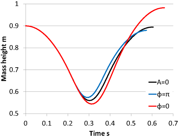
Figure 3. Verification of the pelvic movement. We plotted the results until the mass height was at a peak after jumping. When the phase difference was 0 rad, the mass height became higher than the fall height. On the other hand, when the phase difference was rad, the mass height after jumping became lower than that on the condition that the pelvic rotation amplitude 0°.
To utilize the phase difference between the mass movement and the pelvic movement effectively, the SLIP2 model must land with the defined joint angle of the pelvis and hip roll at landing. When the joint angles at landing are different from the defined angles, the phase of the mass movement in the vertical direction while standing differs from that of the pelvic movement. The defined angle can be calculated by the difference between the phases to change the effectiveness of the pelvic movement for attaining jumping power. To solve this problem, we estimated the next landing time from the velocity of the mass in the vertical direction on takeoff, and moved the pelvis to the angle θpelvis_ini to start pelvic oscillation from the same angle as in the previous running cycle. Because the movement of the mass traces a parabola in the flight phase, the next landing time Tlanding is given by:
where Vz is the velocity of the mass in the vertical direction at takeoff.
The pelvic movement in the flight phase is expressed as follows:
where θpelvis_ini is the initial angle of the pelvis at landing; θpelvis_off, the angle of the pelvis at takeoff; and tflight, the time of the flight phase.
Foot Placement Control
We used a foot placement controller to control running speed in the manner of Raibert (1986). This is achieved by moving the leg to an appropriate position with respect to the body during the flight phase in the SLIP model. The position of the foot with respect to the body when landing has a great influence on the running speed. In steady running without changing the running speed, the SLIP model should land its foot at the mid-point of the distance that the SLIP model moves while standing (Figure 4A). When the SLIP model accelerates, the SLIP model should land in front of the mid-point for utilizing forward-fall rotation (Figure 4B). In simulated research, Wensing et al., extended this method for 3D running (Wensing and Orin, 2013), and Zhao et al. used same control method for locomotion in rough terrains (Zhao and Sentis, 2012). As mentioned above, running can be modeled by a SLIP or SLIP2. Some researchers developed the running control without foot placement controller (Lee and Goswami, 2012). However, we assume that the foot placement controller used for the SLIP model embodies one of the key principles of human running. In fact, humans change their foot position at the landing phase depending on the running speed (Cavagna et al., 1988). To implement this principle of human running, we used a foot placement controller. The foot position is given by:
where xf is the foot placement; x, the body mass placement; T, the stance time; , the reference running speed, and K, the control gain.
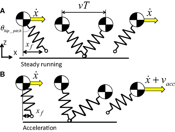
Figure 4. Foot placement control. The position of the foot with respect to the body when landing has a great influence on the running speed. In steady running without changing the running speed, the SLIP model should land its foot at the mid-point of the distance that the SLIP model moves while standing (A). When the SLIP model accelerates, the SLIP model should land in front of the mid-point for utilizing forward-fall rotation (B).
Finally, the robot determined the angle of its hip pitch joint for landing according to the foot position and moved the hip pitch joint by landing. The angle of the hip pitch joint for landing is given by:
where lleg is the leg length. The control block diagram is shown in Figure 5.
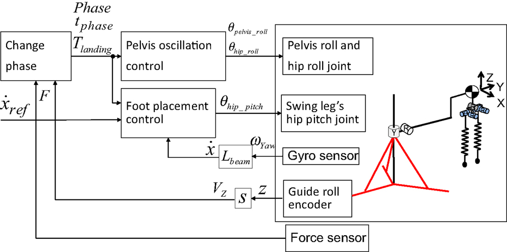
Figure 5. Block diagram of running control. We implemented a pelvic oscillation controller for attaining jumping power and a foot placement controller for controlling the running speed.
Development of Running Robot with linear spring leg
Next, we sought to develop a running robot that could successfully execute running motion based on the SLIP2 model. We determined the requirements for angular velocity and torque in the hip roll joint on the basis of human running data acquired by Ferber et al. (2003). We also fixed the requirements for the angular velocity of the pelvis roll joint on the basis of human running data acquired by Schache et al. (2002) and the requirements for the hip pitch joint based on our human running data. To the best of our knowledge, no work has previously been conducted on the torque of the pelvis roll joint. We calculated these requirements by substituting appropriate values in the equation of motion. The requirements for the angular velocity and torque of the pelvis and hip joints are summarized in Table 1.
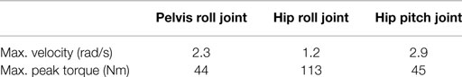
Table 1. Requirements.
We chose 150-W DC motors (Maxon Co., Ltd.), timing belts, and harmonic drives to actuate the pelvis and hip joints (Figure 6). The developed robot mimicked the human’s parameters about the mass of the whole body, the mass of the leg, the width between the hip joints, the length of the leg, and the leg stiffness (Table 2). These parameters are significant in the SLIP2 model. To adjust the mass, masses can be mounted on the upper part of the robot. We selected a compression spring, shaft, set collar, and linear bush for the leg spring. Owing to this mechanism, the compression spring is not detached from its upper and lower parts when the spring is at free length. In addition, the compression springs can be replaced with others by adjusting the distance between the set collar and the linear bush. We fixed the range of the spring’s stiffness from 16 to 40 kN/m on the basis of the previous study (Dalleau et al., 1998). The developed robot is also equipped with an inertial measurement unit (IMU) named Waseda bioinstrumentation-4 (WB-4) on the body for measuring its posture. WB-4 has a 3-axis accelerometer sensor; 3-axis gyroscope; and 3-axis magnetometer (Figure 7) (Lin et al., 2011). The developed robot with a pelvis is shown in Figure 8.
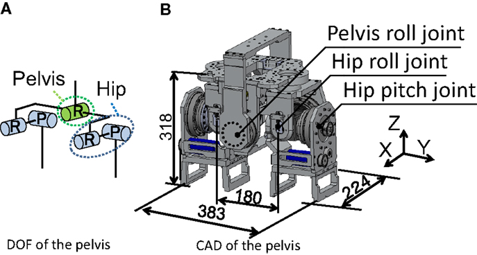
Figure 6. Developed pelvis. Length are in mm. The pelvis had five joints; one pelvis roll joint, two hip pitch joints, two hip roll joints (A). We chose 150-W DC motors, timing belts, and harmonic drives to actuate the pelvis and hip joints (B).
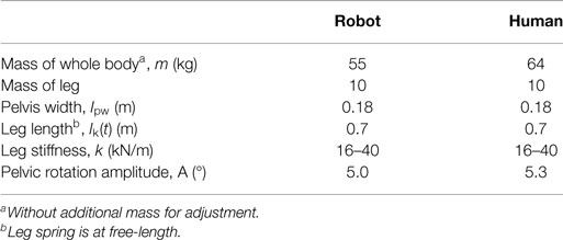
Table 2. Configuration of the developed robot and human.
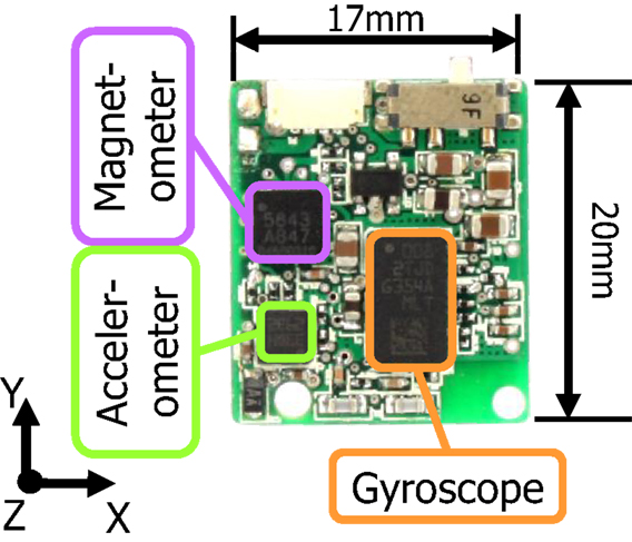
Figure 7. Inertial measurement unit (IMU) implemented on the robot body. The IMU is referred to as the WB-4 (Waseda bioinstrumentation-4) sensor, which has a 3-axis accelerometer sensor, 3-axis gyroscope, and 3-axis magnetometer.
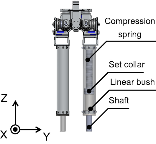
Figure 8. Computer aided design of developed running robot. To adjust the mass, weights can be mounted on the upper part of the robot. A compression spring, shaft, set collar, and linear bush served as the spring of the leg. Owing to this mechanism, the compression spring is not detached from its upper and lower parts when the spring is at free length.
Results
Hopping Experiment
To evaluate the pelvic oscillation controller for attaining jumping power, we performed a hopping experiment by using the developed robot. In this experiment, the robot began the experiment in the standing position and started to move its pelvis according to the pelvic oscillation controller. The robot could detect whether it stood on the ground by force sensors implemented under the floor. On the basis of the ground reaction force data, the robot oscillated its pelvis in the stance phase and moved the pelvis to the landing angle by next landing in the flight phase. The hip roll joints were controlled to move in the opposite direction of the pelvis to maintain the leg perpendicular to the ground at all times. The hip pitch joint was controlled according to the foot placement controller with a reference running speed of 0 m/s to maintain vertical hopping. The robot motion was restricted to the vertical and horizontal directions with a developed guide (Figure 9), which had two passive joints, and was connected to the body of the robot. Because this allowed the robot to go around the guide, we could calculate its running speed by the angular velocity of the body in the yaw direction, ωYaw, measured by a gyro sensor implemented in the robot’s IMU. The running speed was given by:
where Lbeam is the length of the beam connected to the robot’s body and the pole of the guide. In this research, it was 1.5 m.
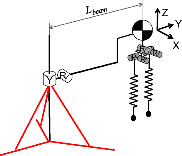
Figure 9. Degrees of freedom (DOF) of the developed running robot with a 2-DOF running guide. The robot motion was restricted to the vertical and horizontal directions with the developed guide. It had two passive joints and was connected to the robot’s body to allow the robot to go around the guide.
To measure the vertical displacement of the robot, a rotational encoder was implemented on the roll joint of the guide. When the leg spring is at free length, the body mass height is 1.1 m. We calculated the vertical velocity of the body mass from its displacement data in this experiment. The leg stiffness was based on the human running data. And the phase difference was also determined from the human running data; . For evaluating the effect of the pelvic movement, we had this experiment under the condition that the amplitude of the pelvic oscillation was 0.5°, 2°, 5° with the landing time estimation, and 5° without the landing time estimation.
Figure 10 shows the mass height of the body in the hopping experiment. When the leg spring is at free length, the body mass height is 1.1 m. A body mass height that exceeded 1.1 m indicated that the robot hopped. When the amplitude of the pelvic oscillation was 0.5°, the robot could not hop. When the amplitude was more than 2°, the robot successfully hopped after a few oscillations. From these results, the robot could hop higher according to the amplitude of the pelvic oscillation. In the experiment without the landing time estimation, however, the robot could not maintain its hopping. After three hops, the mass height of the body decreased. On the other hand, by using the landing time estimation, the robot maintained its hopping and the mass height increased.
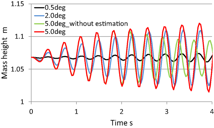
Figure 10. Body mass height during hopping experiments. When the leg took off the ground, the mass height was 1.1 m. A mass height above 1.1 m indicates that the robot hopped. When the amplitude of the pelvic oscillation was 0.5°, the robot could not hop. When the amplitude was more than 2°, the robot successfully hopped after a few oscillations. In the experiment without the landing time estimation, however, the robot could not maintain its hopping. On the other hand, the robot continued to hop and the mass height increased by using the landing time estimation.
This experimental result suggests that pelvic movement in human running contributes to the increase in takeoff force. And that the amplitude of the pelvic oscillation and the difference in the pelvic rotational phase influence the effectiveness for the increase in takeoff forces. Nevertheless, it is common to instruct superior runners to emulate a running form in which the pelvis is stationary. This is because the pelvic movement in running can easily hurt the pelvis (Schache et al., 2002). To use the pelvic movement effectively and safely, it is assumed that runners should train their muscles around the trunk and pelvis. As in this example, it is possible that some motions posing a risk of injury improve human physical performance; if so, using a humanoid robot would allow us to verify the effects safely. It is also possible that humans use resonance by not only the pelvis but also other parts of the body (e.g., arms).
Running Experiment
We performed a running experiment by using the developed robot to evaluate the pelvic oscillation and foot placement controllers. The experimental conditions were identical to those for the hopping experiment, except for the reference running speed of 0.1 m/s. The pelvic oscillation amplitude was 5.0°, and the control gain of the foot placement control was 0.15.
Figure 11 shows photographs of the experiment, and Figure 12 shows the running speed. We measured the running speed from gyro sensor data during each flight phase because the foot placement controller mainly affects the running speed during the flight phase. The robot started its pelvic oscillation and started to hop and run after a few oscillations. The robot succeeded in running at approximately 0.1 m/s.
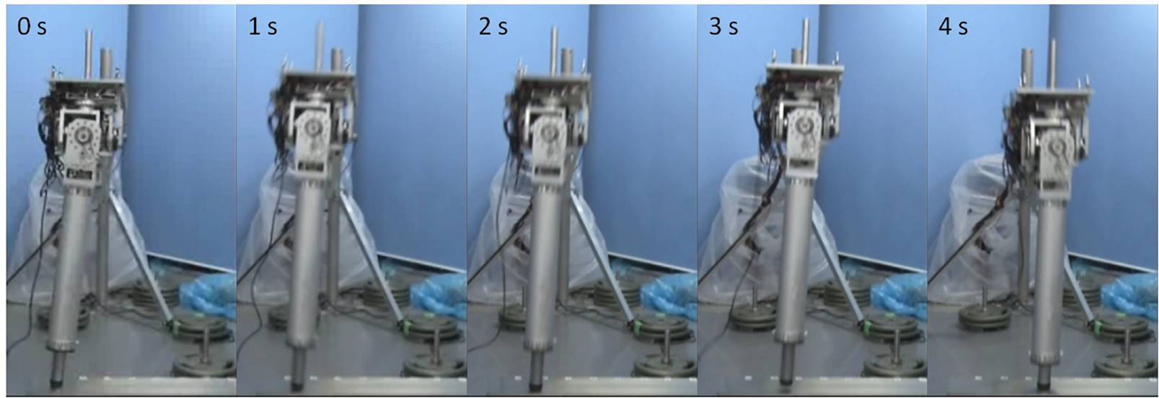
Figure 11. Running experiment. The robot began its pelvic oscillation at 0 s, and started to hop and run after a few oscillations at 1 s. Then, the robot accelerated in forward direction by the foot placement control. In this experiment, the robot used only its pelvic motion for attaining jumping power.
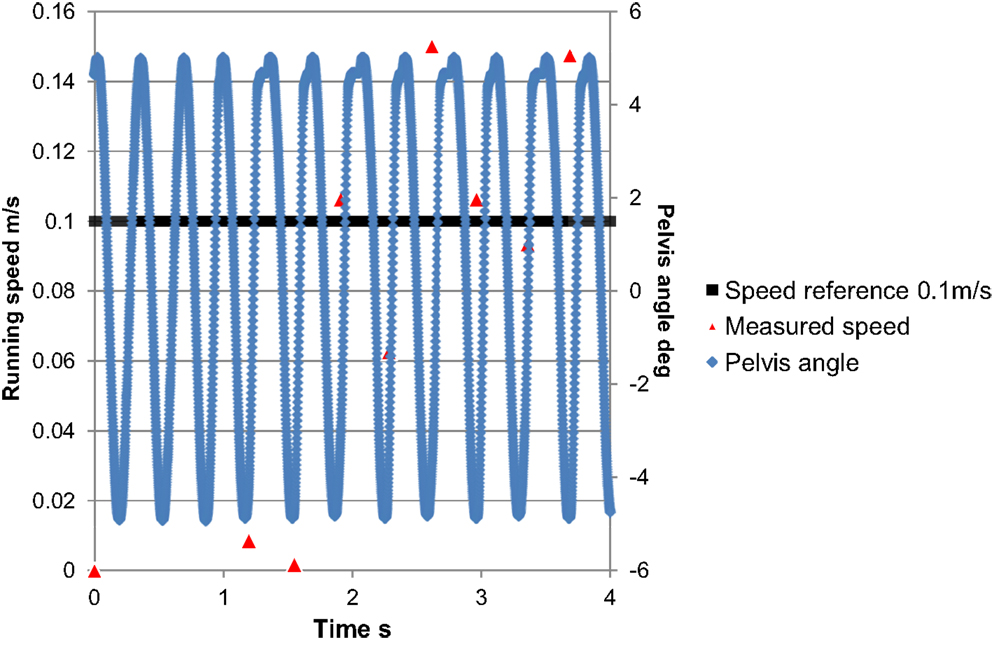
Figure 12. Running speed transition. The robot successfully ran according to the reference running speed of approximately 0.1 m/s.
Although the developed robot has the potential to run at a speed of up to roughly1 m/s, it cannot run as fast as a human. This is because the robot used only its pelvis while standing and its hip pitch joint during the flight phase. It did not kick the ground by actively moving its hip joint. This movement and its stabilization are required to run at a higher speed. In human running, the trunk and arms are said to be used for stabilization (Collins et al., 2009). Therefore, the upper body of the robot should be developed to allow it to actively kick the ground with its hip joint. As mentioned above, successful running has been demonstrated in some humanoid robots. However, these robots use only the hip joint, and not pelvic movement, for kicking. The results of this study suggest that pelvic movement could be effective for improving the running speed of these humanoid robots.
Conclusion and Future Work
Here, we described an analysis of human running motion focused on pelvic movement in the frontal plane, and developed the SLIP2 model and a running control system. From the analysis, we concluded that pelvic movement in the frontal plane, which resembles a sine wave during the stance phase, can help to increase takeoff forces and absorb landing impacts. We then newly developed the SLIP2 model, composed of the SLIP model, as well as a pelvis equipped with running control methods including pelvic oscillation and foot placement controllers. To evaluate the SLIP2 model and the running control methods, we executed hopping and running experiments with the developed robot. The results indicated that pelvic movement can help to increase the jumping force and absorb the impact. The pelvic rotational phase difference had an influence on the increase in takeoff forces.
These results suggest that the running robot can run at a higher speed by using kicking and pelvic movement. Humans can run stably at high speeds because the moment generated by the ground reaction force and their leg movement are compensated for by the use of their upper body and arms. In future studies, we intend to combine the SLIP2 model with an upper body to construct a new full-body model that mimics this characteristic of human running. Finally, we will develop a new stabilization control method that uses the upper body and arms for high speed running by means of kicking and pelvic movement.
Conflict of Interest Statement
The authors declare that the research was conducted in the absence of any commercial or financial relationships that could be construed as a potential conflict of interest.
Acknowledgments
This study was conducted with the support of the Research Institute for Science and Engineering, Waseda University; Institute of Advanced Active Aging Research, Waseda University, and as part of the humanoid project at the Humanoid Robotics Institute, Waseda University. It was also supported in part by the MEXT/JSPS KAKENHI Grant No. 25220005 and 25709019; Mizuho Foundation for the Promotion of Sciences; SolidWorks Japan K.K.; DYDEN Corporation and Cybernet Systems Co., Ltd.; we thank all of them for the financial and technical support provided.
Supplementary Material
The Supplementary Material for this article can be found online at https://www.frontiersin.org/article/10.3389/frobt.2015.00017
Video S1. Running experiment. The robot began its pelvic oscillation at 0 s, and started to hop and run after a few oscillations. Then, the robot accelerated in forward direction by the foot placement control. In this experiment, the robot used only its pelvic motion for attaining jumping power.
References
Blickhan, R. (1989). The spring-mass model for running and hopping. J. Biomech. 22, 1217–1227. doi: 10.1016/0021-9290(89)90224-8
Cavagna, G. A., Franzetti, P., Heglund, N. C., and Willems, P. (1988). The determinants of the step frequency in running, trotting and hopping in man and other vertebrates. J. Physiol. 29, 81–92.
Chapman, A. E., and Caldwell, G. E. (1983). Factors determining changes in lower limb energy during swing in treadmill running. J. Biomech. 16, 69–77. doi:10.1016/0021-9290(83)90047-7
Collins, S. H., Adamczyk, P. G., and Kuo, A. D. (2009). Dynamic arm swinging in human walking. Proc. Biol. Sci. 276, 3679–3688. doi:10.1098/rspb.2009.0664
Dalleau, G., Belli, A., Bourdin, M., and Lacour, J. R. (1998). The spring-mass model and the energy cost of treadmill running. Eur. J. Appl. Physiol. 77, 257–263. doi:10.1007/s004210050330
Farley, C. T., and González, O. (1996). Leg stiffness and stride frequency in human running. J. Biomech. 29, 181–186. doi:10.1016/0021-9290(95)00029-1
Ferber, R., Davis, I. M., and Williams, D. S. III (2003). Gender differences in lower extremity mechanics during running. Clin. Biomech. 18, 350–357. doi:10.1016/S0268-0033(03)00025-1
Grizzle, J. W., Hurst, J., Morris, B., Park, H. W., and Sreenath, K. (2009). “MABEL, a new robotic bipedal walker and runner,” in 2009 American Control Conf., St. Louis, MO, 2030–2036.
Gunther, M., and Blickhan, R. (2002). Joint stiffness of the ankle and the knee in running. J. Biomech. 35, 1459–1474. doi:10.1016/S0021-9290(02)00183-5
Hashimoto, K., Hattori, K., Otani, T., Lim, H. O., and Takanishi, A. (2014). Foot placement modification for a biped humanoid robot with narrow feet. ScientificWorldJournal 2014, 259570. doi:10.1155/2014/259570
Hashimoto, K., Takezaki, Y., Lim, H. O., and Takanishi, A. (2013). Walking stabilization based on gait analysis for biped humanoid robot. Adv. Robot. 27, 541–551. doi:10.1080/01691864.2013.777015
Honda Motor Company Ltd. ASIMO, Honda Motor Company Ltd. Available at: http://www.honda.co.jp/ASIMO/
Hyon, S., Emura, T., and Mita, T. (2003). Dynamics-based control of a one-legged hopping robot. J. Syst. Control Eng. Proc. Inst. Mech. Eng. I 217, 83–98. doi:10.1177/095965180321700203
Kajita, S., and Espiau, B. (2008). “Chapter 16 legged robots,” in Springer Handbook of Robotics, Vol. C, eds B. Siciliano and O. Khatib (Berlin: Springer), 361–389.
Lee, S. H., and Goswami, A. (2012). A momentum-based balance controller for humanoid robots on non-level and non-stationary ground. Auton. Robots 33, 399–414. doi:10.1007/s10514-012-9294-z
Lin, Z., Zecca, M., Sessa, S., Bartolomeo, L., Ishii, H., and Takanishi, A. (2011). “Development of the wireless ultra-miniaturized inertial measurement unit WB-4: preliminary performance evaluation,” in 33rd Annual International Conference of the IEEE EMBS, Boston, MA, 6927–6930.
McMahon, T., and Cheng, G. (1990). The mechanics of running: how does stiffness couple with speed? J. Biomech. 23, 65–78. doi:10.1016/0021-9290(90)90042-2
Niiyama, R., Nishikawa, S., and Kuniyoshi, Y. (2012). Biomechanical approach to open-loop bipedal running with a musculoskeletal athlete robot. Adv. Robot. 26, 383–398. doi:10.1163/156855311X614635
Ogura, Y., Shimomura, K., Kondo, H., Morishima, A., Okubo, T., Momoki, S., et al. (2006). “Human-like walking with knee stretched, heel-contact and toe-off motion by a humanoid robot,” in 2006 IEEE/RSJ International Conference on Intelligent Robots and Systems, Beijing, 3976–3981.
Pozzo, T., Berthoz, A., and Lefort, L. (1990). Head stabilization during various locomotor tasks in humans. Exp. Brain Res. 82, 97–106. doi:10.1007/BF00230842
Schache, A. G., Branch, P., Rath, D., Wrigley, T., and Bennell, K. (2002). Three-dimensional angular kinematics of the lumbar spine and pelvis during running. Hum. Mov. Sci. 21, 273–293. doi:10.1016/S0167-9457(02)00080-5
Tajima, R., Honda, D., and Suga, K. (2009). “Fast running experiments involving a humanoid robot,” in 2009 IEEE International Conference on Robotics and Automation, Kobe, 1571–1576.
Takenaka, T., Matsumoto, T., Yoshiike, T., and Shirokura, S. (2011). Running gait generation for biped robot with horizontal force limit. JRSJ 29, 93–100. doi:10.7210/jrsj.29.849
Wensing, M. P., and Orin, E. D. (2013). “High-speed humanoid running through control with a 3D-SLIP model,” in 2013 IEEE/RSJ International Conference on Intelligent Robots and Systems, Tokyo, 5134–5140.
World Medical Association. (1964). Declaration of Helsinki. Helsinki, FL: World Medical Association.
Keywords: humanoid, human motion analysis, running, pelvis, joint elasticity
Citation: Otani T, Hashimoto K, Yahara M, Miyamae S, Isomichi T, Hanawa S, Sakaguchi M, Kawakami Y, Lim H-o and Takanishi A (2015) Utilization of human-like pelvic rotation for running robot. Front. Robot. AI 2:17. doi: 10.3389/frobt.2015.00017
Received: 21 April 2015; Accepted: 18 June 2015;
Published: 08 July 2015
Edited by:
Giuseppe Carbone, University of Cassino and South Latium, ItalyReviewed by:
Ye Zhao, The University of Texas at Austin, USAFernando Gomez-Bravo, Huelva University, Spain
Mingfeng Wang, University of Cassino and South Latium, Italy
Copyright: © 2015 Otani, Hashimoto, Yahara, Miyamae, Isomichi, Hanawa, Sakaguchi, Kawakami, Lim and Takanishi. This is an open-access article distributed under the terms of the Creative Commons Attribution License (CC BY). The use, distribution or reproduction in other forums is permitted, provided the original author(s) or licensor are credited and that the original publication in this journal is cited, in accordance with accepted academic practice. No use, distribution or reproduction is permitted which does not comply with these terms.
*Correspondence: Takuya Otani, Graduate School of Advanced Science and Engineering, Waseda University, #41-304, 17 Kikui-cho, Shinjuku-ku, Tokyo 162-0044, Japan, t-otani@takanishi.mech.waseda.ac.jp