An Ultrasound Robotic System Using the Commercial Robot UR5
 Kim Mathiassen
 Jørgen Enger Fjellin1
 Kyrre Glette
 Ole Jakob Elle
- 1Robotics and Intelligent Systems, Department of Informatics, University of Oslo, Oslo, Norway
- 2The Intervention Center, Oslo University Hospital, Oslo, Norway
- 3Medical Faculty, University of Oslo, Oslo, Norway
The use of robots in health care has increased dramatically over the last decade. One area of research has been to use robots to conduct ultrasound examinations, either controlled by a physician or autonomously. This paper examines the possibility of using the commercial robot UR5 from Universal Robots to make a tele-operated robotic ultrasound system. Physicians diagnosing patients using ultrasound probes are prone to repetitive strain injuries, as they are required to hold the probe in uncomfortable positions and exert significant static force. The main application for the system is to relieve the physician of this strain by letting the them control a robot that holds the probe. A set of requirements for the system is derived from the state-of-the-art systems found in the research literature. The system is developed through a low-level interface for the robot, effectively building a new software framework for controlling it. Compliance force control and forward flow haptic control of the robot was implemented. Experiments are conducted to quantify the performance of the two control schemes. The force control is estimated to have a bandwidth of 16.6 Hz, while the haptic control is estimated to have a bandwidth of 65.4 Hz for the position control of the slave and 13.4 Hz for the force control of the master. Overall, the system meets the derived requirements and the main conclusion is that it is feasible to use the UR5 robot for robotic ultrasound applications.
1. Introduction
Over the last decade, robots have been used in health care for a wide range of applications, from surgical robots (Dogangil et al., 2010) to robots used for patient rehabilitation (Krebs et al., 2003). There have been many research projects on Robotic Ultrasound Systems, defined as the combination of ultrasound imaging with a robotic system in medical interventions (Priester et al., 2013). Some of the goals of the research in these areas are to:
• Reduce or prevent musculoskeletal disorders for the physician (Salcudean et al., 1999; Nakadate et al., 2010b).
• Enable remote diagnosis (Vilchis Gonzales et al., 2001; Vieyres et al., 2003).
Our motivation for this research was discussions with physicians in the radiology department. One particular radiologist had repetitive strain problems in his shoulder, and was interested in mechanisms to reduce the physical impact of using the ultrasound probe. A large survey was conducted in Evans et al. (2009) and 90% of the respondents were said to be scanning in pain. The most common site of pain was the shoulder, and the second most common site of pain was the neck (Evans et al., 2009). A tele-operated ultrasound probe would mean that the force needed to control the probe could be reduced; additionally, the physician would not need to twist to face the patient (the site of the probe) and look at the ultrasound image.
Researchers have made robotic systems that hold the ultrasound probe for the physician, and the physician controls the robot using a haptic device. The force the robot uses on the patient is scaled down on the haptic device, thus reducing the strain. In both Salcudean et al. (1999) and Nakadate et al. (2010b), such robotic systems are presented.
As a result of creating a robotic system to control the ultrasound probe, we can also easily extend this to be used for remote diagnosis. In this setting, the physician and the robot are not co-located. Light-weight transportable systems, which can be used in ambulances and on space stations are reported in Gourdon et al. (1999), Vieyres et al. (2003), Courreges et al. (2004), Arbeille et al. (2008), Bruyère et al. (2010), and Charron et al. (2010). In De Cunha et al. (1998), a physician controls a ultrasound probe in order to guide a surgeon at a remote site. A cable driven robot is reported in Vilchis Gonzales et al. (2001), Vilchis et al. (2003), and Martinelli et al. (2007), where a system is designed to perform follow up investigations on pregnant women. A system for diagnosis of venous thrombosis is described in Vilchis-Gonzales et al. (2007) and Vilchis-Gonzalez et al. (2007). In Salcudean et al. (1999) and Abolmaesumi et al. (2002), the development of a system for carotid artery examinations to diagnose occlusive disease is described. This also includes shared control of the robot between the physician and a visual servoing algorithm based on cross-correlation. In Nakadate et al. (2010a), another system for examining carotid artery is reported, but here the system does an automatic measurement of the wave intensity at the common carotid artery. A system for remote diagnosis of the human abdomen is reported in Masuda et al. (2001, 2011), Mitsuishi et al. (2001), and Koizumi et al. (2004) focusing on tele-echography in general while investigating dynamic switching of the control algorithm based on the diagnostic task. In Koizumi et al. (2009), a system is made for remote diagnosis of dialysis-related amyloid arthropathy. All the systems presented above describe custom-made robots, while Santos and Cortesao (2015) use a system based on a commercially available industrial robot. It presents a hierarchical force and orientation control, which estimates the environment stiffness using active observers.
Some of the remote-controlled systems presented above also attempt to automate certain tasks. This includes Pierrot et al. (1999) and Abolmaesumi et al. (2002), which reconstructs the carotid artery in 3D and Nakadate et al. (2010a) for automatic measurement of the wave intensity at the common carotid artery. Other systems are made solely for automation, and not do not enable remote control. This includes Pierrot et al. (1999), where a system to create 3D images to monitor cardiovascular disease over time is described. A system for 3D reconstruction of lower limb arterial vessels is described in Janvier et al. (2008, 2010), and in Mustafa et al. (2013), an autonomous system is developed to perform liver screening using a Mitsubishi Electric industrial robot.
This paper lists the requirements for a tele-operated robotic ultrasound system, which are extracted from a review of the current literature. The main contribution of this paper is to examine the feasibility of using a collaborative industrial robot for a tele-operated robotic ultrasound system. Unlike other research done with industrial robots in this area, the robot used in this study has built-in safety features, which means that it will be conducive to safe human–robot interaction. Other studies have developed their own robot with their own safety mechanisms, but unlike the robot used in this study they are not certified as collaborative robots complying to the EN ISO 10218-1:2006 standard. Using a robot that has already achieved these standards means that it will likely take less time to certify it for the clinical market. While the work presented in this paper is not high in novelty, it is important incremental work toward being able to use such a system in a clinical setting.
The requirements state what performance level the robotic ultrasound system must achieve. We developed a software framework for interfacing with the hardware and controlling the robot, and with this ran studies to assess whether the system achieves the desired performance level.
The remainder of the paper is organized as follows: in Section 2, the requirements for our system are investigated and derived. In Section 3, the development of the robotic ultrasound system is explained, and experiments to assess the system are described in Section 4. Section 5 evaluates the performance of the system and Section 6 discusses these results. Finally, Section 7 concludes and indicates further work.
2. System Requirements
This section will identify a set of quantitative performance metrics and define the best performance found for these metrics based on the state-of-the-art. We envision two main applications for the system: prevention of repetitive strain injuries for the physician and performing remote ultrasound examinations. In the first application, the physician will use a haptic device to control the robot holding the probe, and the haptic device will scale down the forces and enable the physician to choose more comfortable holding positions. In the second application, the system might be used in community health-care centers in rural areas. If the local physician does not get a satisfactory result with the initial examination, then they can contact a hospital so a more experienced physician can perform the examination remotely (thus saving time for the patient). In order to be able to equip community health-care centers with an ultrasound robotic system, it should be low cost. The applications discussed above will require two operation modes for the system:
• Force control mode: the slave robot is controlled using force and torque measurements
• Tele-operation mode: the slave robot is controlled by the physician using a haptic device.
Force control is widely used in the literature, especially to achieve a constant pressure when monitoring vessels (Pierrot et al., 1999; Abolmaesumi et al., 2002). A tele-operation mode is used by the majority of the systems and enables the physician to easily control the probe. In this paper, the tele-operation is limited to a co-located setting, i.e., the physician and the patient are in the same room. However, the system is designed so that it can easily be extended to remote settings.
The platform development is divided into three parts, as done in Courreges et al. (2008):
• Slave site: location of the patient, the robot, ultrasound machine, and medical staff to monitor the procedure.
• Communication link: the data link and protocols used between the two sites.
• Master site: location of the physician, which controls the robot and views the ultrasound images.
Figure 1 gives an overview of the system architecture, and the blocks in the figure are treated in the subsequent sections. This figure is a merge of the architectures found in Vilchis Gonzales et al. (2001), Abolmaesumi et al. (2002), Vilchis et al. (2003), and Courreges et al. (2008), and adapted to our case.
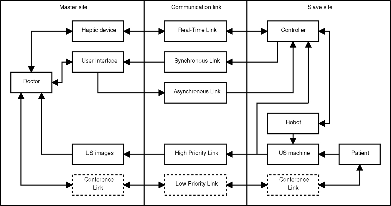
Figure 1. System overview showing the three main parts of the system and the flow of information denoted by arrows. The slave site consists of the patient, a robot holding an ultrasound probe and a controller for controlling the robot. At the master site, the physician is controlling the robot using a haptic device while viewing the ultrasound images acquired at the slave site. The communication links are classified based on their required properties.
2.1. Slave Site
The slave site traditionally consists of the patient undergoing an examination and a robot holding an ultrasound probe that performs the examination. The physician is located at the master site and controls the slave robot using a haptic (master) device. For the haptic device to render the forces between the ultrasound probe and the patient for the physician, they need to be measured, and this is usually done by a force/torque sensor on the slave robot. While the physician controls the master robot he views the ultrasound images obtained at the slave site, thus these images need to be transmitted to the master site. Usually, some local medical staff is present at the slave site for assisting the physician and support the patient.
2.1.1. Safety
One very important requirement of the slave site is patient safety. We will incorporate three levels of safety: hardware, software, and user input. If a hardware component fails, it must be detected and operation must stop. The hardware layer should also have sanity checks of the user input, for instance maximum allowed velocity and motor current to prevent overly fast robot motion and overly high robot force. The robot should also be relatively light-weight because this will reduce the damage caused if the robot impacts with the patient. In the software layer, it is possible to have more sophisticated safety features. The forces should be measured and the software layer should prevent the forces applied to the patient from being too high. At the user level, the physician should be able to easily stop the robot using a switch and the patient should be given a dead man’s switch that safely stops the robot in case the patient feels discomfort or pain. These requirements are consistent with the requirements listed in Pierrot et al. (1999).
2.1.2. Robot
While few projects give quantitative information about the properties of their robots, an exception is Pierrot et al. (1999). Their robot uses a control loop frequency of 100 Hz, has a repeatability of 0.05 mm and a payload of 20 N. Absolute accuracy of the robot is not important in this application as it is not required to know the exact position of the probe relative to the base of the robot, but rather to have the robot move to the same location given the same user input. We set properties from Pierrot et al. (1999) as the minimum requirement for our system. The probe should be able to be positioned in an arbitrary position and pose, and therefore, the robot should have minimum 6 DOF.
2.1.3. Force Sensor and Control
To find the appropriate force/torque sensor previous studies have been reviewed. The maximum force and torque when performing an ultrasound examination of the carotid artery is reported to be 6.4 N and 0.7 Nm in Salcudean et al. (1999). An average force of 7 N was reported in Goldberg et al. (2001), but the examination type was not specified in this study. Significantly higher values are reported in Boman et al. (2009), with forces up to 100 N during an ultrasound examination. In Courreges et al. (2008), the contact force is said to be in the range 5–20 N. In Pierrot et al. (1999), the force accuracy of their system is given to be 0.1 N.
To avoid saturation of the force sensor, the dynamic range requirement is set to the maximum reported in previous studies (100 N). The force sensing technology has improved significantly since Pierrot et al. (1999) was published, therefore the sensor should easily achieve accuracy better than 0.1 N.
The force control should be able to hold a constant force against the patient, and keep contact with the patient even if there are small patient movements, such as respiratory motion. Movement of the chest during respiration is relatively small and below 5 mm during tidal breathing (De Groote et al., 1997). By analyzing the chest movement given in De Groote et al. (1997), we have estimated that the bandwidth of the respiration is below 1.5 Hz, with its main component at approximately 0.3 Hz. The required bandwidth is set to twice the bandwidth of the respiratory motion according to the Nyquist sampling theorem. Although there could be other disturbances, like coughing or small motions of the patient, only the breathing bandwidth was used to decide the bandwidth requirement, as this process may be modeled fairly accurately. Also, when the probe is not in contact with the patient it should not move, as there are no forces present.
2.1.4. Ultrasound Image
The ultrasound image pixel depth requirement is set to 8 bits, as this is most common (De Cunha et al., 1998; Abolmaesumi et al., 2002; Vilchis et al., 2003). The resolution of the images varies from 180 × 210 in Mebarki et al. (2008) up too 576 × 768 in Bachta and Krupa (2006). We set the requirement to be the maximum found in the literature, i.e., 576 × 768. The frame rate in De Cunha et al. (1998) and Abolmaesumi et al. (2002) is 15 fps. Given that technological advances have increased in both processing and transmission capabilities, the requirement is set to 25 fps.
2.2. Communication Link
Several streams of data need to be sent between the master and slave sites. These streams are based on the streams found in Vilchis Gonzales et al. (2001) and Courreges et al. (2008).
2.2.1. Haptic Stream
The haptic stream transmits forces, torques, and velocities between the master and slave site and should be delivered with low jitter and below a maximum allowed delay (Vilchis Gonzales et al., 2001). This sets hard real-time demands on the link. In both Vilchis Gonzales et al. (2001) and Courreges et al. (2008), an update frequency of 1000 Hz in the haptic loop is used but this is done as a local loop at the master site. The communication may have a lower rate, and possible rates are tested in Vilchis Gonzales et al. (2001), where 100 Hz is classified as very good and 10 Hz as good. As the master and slave site are co-located (i.e., the physician is present locally), the update frequency can be set to the same as the haptic control loop frequency: 1000 Hz. This also means that the force sensor needs an update frequency of 1000 Hz.
2.2.2. Synchronous/Asynchronous Streams
Status information from the slave robot is sent through a synchronous link to be displayed in the user interface. This link is introduced because the information has a lower priority than the information in the haptic loop and should therefore be transmitted through a separate link. If this information does not arrive within the required time, the system will still work, as opposed to the link between the haptic device and the slave robot controller. This means that the link has soft real-time requirements.
Through the user interface, the user can change the parameters of the system and request a mode change between the modes of operation. This information is sent over the asynchronous link and is processed as it arrives in the slave robot controller. The information sent is not commands controlling the robot, thus there are only soft real-time requirements on this link.
2.2.3. Ultrasound Image Stream
The ultrasound images are vital for the physician, and therefore these images should be sent through a high priority link.
2.2.4. Video Conference Stream
This stream is only relevant if the system will be extended to remote tele-operation, therefore, these blocks are marked with dotted lines in Figure 1. In a remote tele-operation setting, it is important for the physician to be able to communicate with the patient, therefore, a video conference link is needed between the sites. The ultrasound images are more important than the conference link, therefore the ultrasound image stream is given priority.
2.3. Master Site
The haptic device is located at the master site and controls the slave robot when the system is in tele-operation mode. The user interface should display all necessary information about the slave system and allow the physician to change operation mode and slave robot parameters.
Requirements for haptic control of an ultrasound probe have been analyzed in Zandsteeg et al. (2010). The analysis is mainly based on previous reports of motion in surgical tasks. The conclusion is that controlling an ultrasound probe using a haptic device requires good force and position tracking up to 2 Hz. The requirement for our system is set to 3 Hz to be consistent with the requirement for the compliance force control.
2.4. Summary of System Requirements
Based on previous research in the field, a set of requirements for a new system has been discussed in the above sections, and summarized in Table 1. The main requirements are the control loop frequencies and bandwidth, which will be evaluated through experiments.
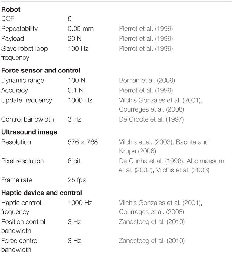
Table 1. System requirements.
3. Developed System
This section describes the development of a robotic ultrasound system, which may be used to perform ultrasound examinations by either using force control or using a haptic device. The following sections will describe the hardware and software setup, the workspace of the developed system and the control schemes for the system.
3.1. Hardware Setup
As seen in the previous sections, it is important that the robotic system is reliable due to patient safety. Therefore, we have chosen to use the six joint industrial robot UR5 from Universal Robots, which cost approximately 24,000$. This robot complies with point 5.10.5 of the standard EN ISO 10218-1:2006, which means that the robot may operate as collaborative robot (Universal Robots, 2010). It is not required to have safety guards between humans and the robot, which makes it possible to use the robot for medical applications. The built-in safety mechanisms include stopping when the robot joint torque deviates from the expected torque. The torque at each joint is calculated at runtime using a theoretical model of the robot, and a protective stop is generated if the torque exceeds 42 Nm for the three first (large) joints and 10 Nm for the last three (small) joints. A protective stop is also generated if joint velocity exceeds 3.2 rad/s or if the external force exceeds 150 N. All these values are evaluated in the robot control hardware provided by the producer and are not adjustable. The robot has an emergency stop button and use harmonic drive gears in all the joints.
The robot is lightweight (18 kg), compared to other industrial robots with similar workspace and payload (the UR5 has a reach of 850 mm and payload of 5 kg). For instance, the ABB robots IRB 1200 and IRB 140 weigh 52 and 98 kg, have a reach of 901 and 810 mm, and a payload of 5 and 6 kg, respectively (ABB Robotics, 2015). Because it is lightweight, an impact with the robot would be less serious than for larger robots. The robot is connected to a computer running the control algorithm using a direct Ethernet connection and a proprietary communication protocol. The computer has a quad core Intel i7-960 3.2 GHz processor, 3 Gb of RAM, and is running Linux 2.6.38 and Xenomai 2.6.0.
The forces and torques are measured using a Gamma SI-65-5 from ATI Industrial Automation, which is a six degree of freedom force/torque sensor with a dynamic range of 200, 65 N, and 5 Nm in the forward force axis, sideways force axes and torque axes, respectively. The resolution is 0.025, 0.0125 N, and 0.75 × 10⁻³ Nm for the respective axes. The device and DAQ unit cost approximately 5,500$. A Phantom Omni is used for haptic control of the robot, and is connected to the control computer (the same computer as the robot) using FireWire. This device has 3 active DOF and 3 passive DOF and costs approximately 800$.
The system is shown in Figure 2, and it shows the robot mounted on a cart with a force/torque sensor and an ultrasound probe attached to the end effector. In the background, a GE System Five ultrasound machine is visible. The ultrasound images are acquired from the VGA port of the ultrasound machine using a VGA2Ethernet device from Epiphan and transmitted over a local gigabit link. The device costs approximated 1,600$. The images are transmitted to the control computer using Ethernet, through a different interface than the robot.
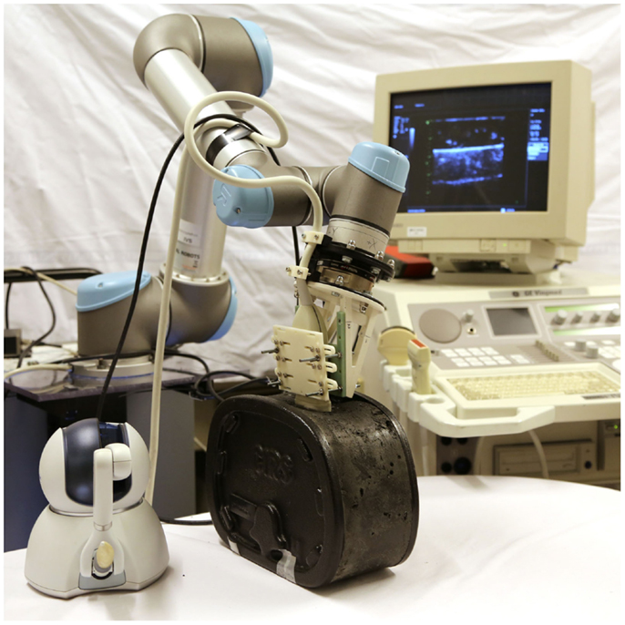
Figure 2. The developed robotic ultrasound system. To the lower left is the Phantom Omni haptic device. To the right is a GE System Five ultrasound machine, and in the center is the UR5 robot holding an ultrasound probe. The phantom is a Abdominal Phantom, Model 057 from CIRS.
3.2. Software Setup
The robot can be controlled at three different levels: graphical user interface, script, and C API. In the graphical user interface, one can program simple tasks, which support the traditional usage of industrial robots. A script can be sent to the robot and executed there, giving more flexibility in programing the robot. However, the script only accepts a limited type of external inputs and is unable to read the force and torque measurements. Therefore, we have used the C API, which is more flexible. A limited number of methods for controlling the robot were provided by the producer, thus a software framework has been implemented. The framework includes robot kinematics and control, safety features, interfaces to external sensors and data logging. The kinematics and control are implemented using the Armadillo C++ Linear Algebra Library (Sanderson, 2010).
The robot controller and the haptic controller run on a Linux computer using the real-time extension Xenomai (Xenomai Project, 2012). Xenomai uses a multi-domain approach to create a real-time system. The real-time processes run in a domain that has higher priority than the Linux kernel. This causes these processes to execute before any other system processes. The real-time processes cannot perform any system calls (such as file operations) as this causes them to be outside the real-time domain, because they must compete with all the other processes for CPU time.
Because the robot is implemented as a device, when the control program interfaces with the robot, it has to use file operations to communicate. This makes the control program switch a non-real-time domain. This happens twice each cycle: once when data from the robot is received and once when control data is sent to the robot. The robot communicates with the computer at 125 Hz, thus performing 250 switches per second. An experiment described in Section 4 will verify that the real-time conditions are met.
The user interface is made in Labview, and shown in Figure 3; it is a separate program, which increases the robustness of the control program and separates it from the real-time processes. The connection from the user interface to the control program is currently done using real-time pipes but can easily be changed so that it can be run on another computer (for use in remote-control applications).
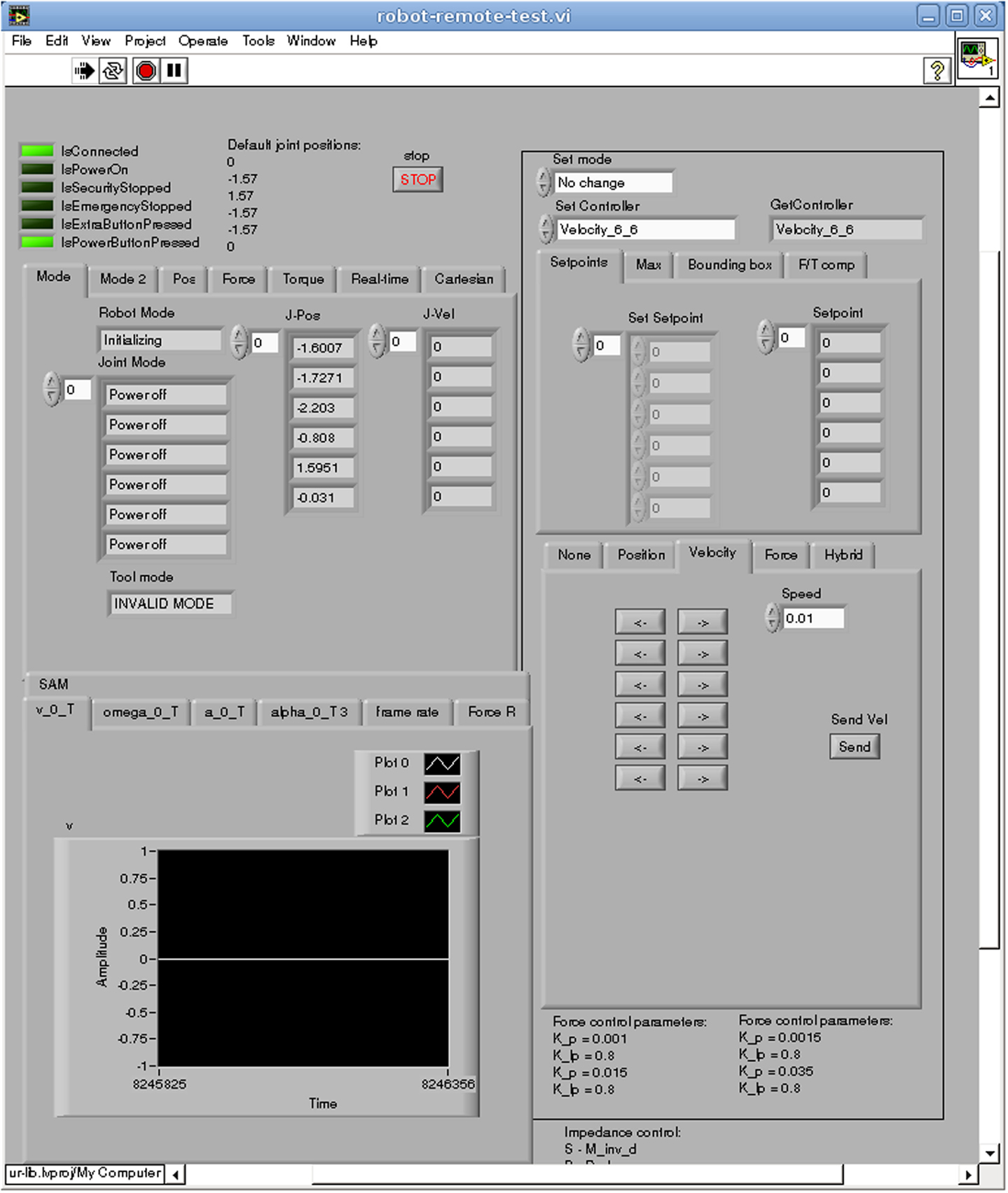
Figure 3. The user interface of the system, where status information about the robot is shown, control modes are selected and sensor data displayed.
The ultrasound images are acquired using proprietary software provided by Epiphan and the receiving of Ethernet packets is done in a separate process. The haptic device is controlled in a separate process using its proprietary software. Both these processes communicate with the robot control program using real-time pipes.
3.3. Dexterous Workspace Analysis
To find a space where the physician may perform an examination unhindered, the dexterous workspace of the robot is analyzed. The dexterous workspace is the set of points that can be reached with any arbitrary orientation (Siciliano et al., 2009), or more specifically a subset of orientations usable by a physician. In Salcudean et al. (1999), the orientation of the probe was analyzed during a carotid artery examination; it was found that the physician oriented the probe within a cone with an arc of 90° pointing toward the examination area. As our application is more general, we will use an arc of 120° to define the dexterous workspace.
The dexterous workspace of the UR5 robot was found by sampling the reachable workspace of the robot. A cube of 1.8 m × 1.8 m × 0.9 m has been sampled with points 20 mm apart, and all possible orientations in the cone have been sampled with a spacing of 2°. If an inverse kinematic solution can be found for all the orientations, the point is within the dexterous workspace. Because an ultrasound probe is attached to the end effector of the robot, an offset has been used in order to calculate the modified (likely reduced) dexterous workspace. The offset is a (0.0, 0.0282, 0.1759) translation and an angle of 27.89°. These values are taken from the CAD drawings of the ultrasound probe mounting.
Two simulations were conducted. In the first simulation, no tool was attached to the robot, in the second, the ultrasound probe was attached. In both simulations, the cone was pointing downwards. The dexterous workspace found in the two simulations is shown in Figure 4. When no tool is attached to the robot, the dexterous workspace can be approximated as a sphere with a radius of 0.79 m with a non-dexterous region as a cylinder in the middle of the sphere with a radius of 0.19 m. When the tool is introduced, the radius of the sphere is reduced to 0.57 m and the radius of the inner cylinder is increased to 0.37 m. We regard, this as sufficient for conducting ultrasound examinations.
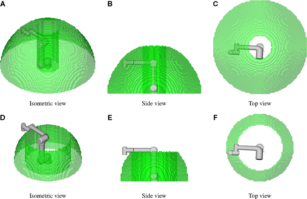
Figure 4. The dexterous workspace for the robot. The probe should be able to have any orientation within a cone with an arc of 120°, and this defines the dexterous workspace. In (A–C), no tool is attached to the robot; and in (D–F), the ultrasound tool is used.
3.4. Control
The UR5 robot has a proprietary internal controller that accepts either joint velocity setpoints or joint trajectory setpoints. We have developed two control schemes on top of the internal controller, compliance control and forward flow haptic control. The kinematics used in the control is given in Supplementary Material. The force/torque measurements are transformed to the ultrasound probe tip and static forces caused by gravitation are compensated using Atkeson et al. (1986). In the below sections, we use the transformed and compensated measurements of force and torque.
3.4.1. Compliance Force Control
Compliance control uses the control law (Siciliano et al., 2009)
where f e is the force error, K is the active compliance matrix and v f is the desired Cartesian velocity vector. Since this control law converts the force error into a desired velocity, it can easily be used with our robot.
The robot vibrates while it is being used, and these vibrations propagate to the attached ultrasound probe. The vibrations are measured by the force/torque sensor, and this might amplify the vibrations and make the controller unstable. To address this problem, we introduce a damping term in the control law
where v d is the Cartesian velocity command to the robot and KI is a damping/integration constant. The damping is a low pass filtering of the setpoint commands to the robot. It can also be viewed as an integration term, smoothing the vibration noise.
Converting the control law to joint space yields
where J is the manipulator Jacobian and is the joint velocity command. Figure 5 shows the control loop. The force setpoint f s is set by the user. The force error f e is calculated as the force setpoint minus the measured force f m. The force control is given in equation (3).
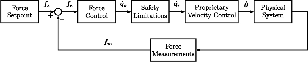
Figure 5. Compliance control.
When finding the inverse of the Jacobian the singular values are limited to 0.1. This is done by not allowing movement that will cause the singular value to go below this threshold. This prevents large velocities in joint space and prohibits the robot from going from the elbow up configuration to the elbow down configuration. In the elbow down configuration, the elbow joint is pointing in the direction of the examination bed, which is unwanted.
The safety limitation block scales down the velocity to be below a maximal allowed joint velocity, while retaining the Cartesian direction of the velocity. The joint velocities are limited by a constant . The vector, is an intermediate vector using the element values from , but limiting the absolute value of the elements to be below . Using directly would result in the robot moving in a different Cartesian direction than intended. Therefore the Cartesian velocity vector must be scaled according to the largest limiting dimension in the joint space. First, the original setpoint and the limited setpoint must be converted into the Cartesian space by
Second, the ratio between the limited and the original setpoints must be determined. This is obtained by
Then the dimension, which is limited the most (has the lowest ratio) must be used to scale the Cartesian velocity setpoint. This value is found by
Finally, the new joint velocity setpoint may be calculated as a scaled version of the original Cartesian velocity setpoint, as shown below
The limited joint velocity setpoint is sent to the proprietary robot velocity controller.
The operator of the system may want to have a constant pressure of the ultrasound probe in one or more dimensions and move the probe in other dimensions. Therefore, a hybrid approach has been implemented, as shown in Figure 6. The user of the system selects which dimensions that are going to be controlled in the velocity domain by setting 1 on the diagonal in the matrix S, which is a 6 × 6 matrix. The force control law is the same, except for the block I − S, which selects the dimensions that will be controlled in the force domain, and the output is now denoted . The velocity control law is only to transform the desired velocity to joint velocities before these values are given to the proprietary velocity controller. The feedback loop exists in the proprietary controller. This yield
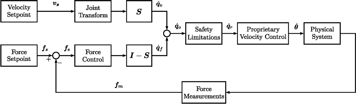
Figure 6. Hybrid velocity and force control.
3.4.2. Forward Flow Haptic Control
The forward flow haptic control is a control scheme where velocity is sent from the master to the slave and force from the slave to the master (Naerum and Hannaford, 2009). The full development of haptic control for our system is described in Fjellin (2013). The control scheme is shown in Figure 7. Starting with the master side, T m is the homogeneous transformation matrix representing the position and orientation of the haptic device. f m is the force measurements of the master, which are used in a feedback loop to control the force of the Omni haptic device. The force control of the Omni haptic device is performed by the proprietary software, but is shown in Figure 7 for completeness. s is the Laplace operator, and represents a time derivation of T m, where the output is Cartesian velocity v m and angular velocity ω m. kf is a scaling factor of the force measured by slave.
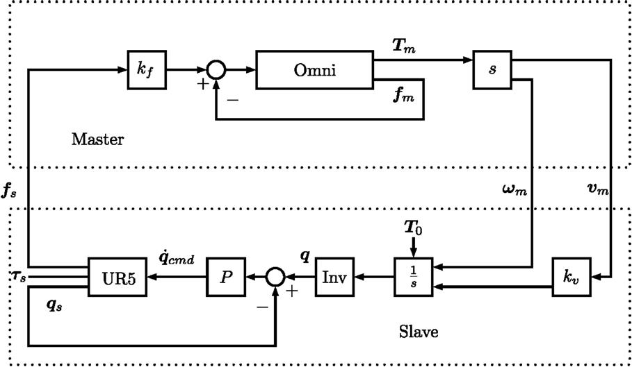
Figure 7. Forward flow haptic control.
On the slave side, the velocity measurements from the master are received and multiplied with by kv, which is a scaling factor for the Cartesian velocities. This factor can be used to scale the slave movement compared to the master. is the Laplacian operator for integration, where T0 is the initial pose of the UR5 robot. This makes it possible to start the tele-operation without aligning the two robots to the same pose. The position obtained after the integration is used with the inverse kinematics of the UR5 robot to find the desired joint positions q. A proportional controller is implemented to follow the desired joint positions with the gain P and where the measured joint positions q s (from the UR5) are used as feedback. The controller provides a velocity command in joint space, which is given to the internal controller of the UR5. The force measurements from the slave f s are given to the master, whereas the torque measurements τ s are not used because the Omni haptic device only has 3 active DOF.
4. Experiments
In order to quantitatively assess the system, a set of experiments have been designed. The requirements in Section 2 will be compared to the specifications given by the product producers. Three areas will be investigated through experiments: real-time performance, compliance force control, and forward flow haptic control. A Model 057 phantom from CIRS was used in all experiments where the probe was in contact with the environment, and ultrasound gel was applied before the experiments.
4.1. Real-Time Performance
The main reason for checking the real-time performance is to verify that the domain switches described in Section 3 do not affect the system. The second reason is to verify that all calculations are done within the required time frame. Four real-time requirements are identified in Section 2 (control of slave, control of master, force measurements, and image capture). As the two control modes (force control and tele-operation) have slightly different real-time properties, two experiments are conducted. The execution time and the period of the control loop are measured using the real-time clock of the control computer, accessed through a Xenomai function call.
4.2. Compliance Force Control
In order to compare the performance of the force control to the requirements given in Section 2, two experiments are conducted. Since the main force from the patient will be in the upwards and downwards direction (z-direction), only this direction will be force controlled during the experiments. An ultrasound probe is attached to the end effector of the robot throughout the experiments.
In the first experiment, the probe is in free air, and the force setpoint is zero. In the system requirements, it is specified that the robot should be stationary in this condition. This experiment will check if the robot is vibrating or deviating from its position. The force, velocity, and position are measured for 7 s. The standard deviation (SD) of the force and velocity along with the total position deviation will be used to evaluate if the robot is sufficiently stationary. The experiment will be run with different parameters for the control loop, and these SDs will be compared for statistical significant difference using the F-test.
In the second experiment, the probe is held at a constant force of 1 N against an ultrasound phantom, and then increased to 5 N. This experiment identifies the impulse response and bandwidth of the force controller, which are important characteristics of the controller. This experiment will also check if the controller is able to maintain a constant force. The bandwidth of the controller was found by first estimating the transfer function and then extracting the bandwidth from the transfer function. This approach is used in all of the experiments where a bandwidth is estimated.
A safety feature that limits the joint velocities was introduced in Section 3.4.1. A third experiment investigates how this feature impacts the impulse response and bandwidth of the force controller.
4.3. Forward Flow Haptic Control
To test the performance of the haptic control loop, three experiments have been conducted. In the first experiment, the robot is moved in free air to evaluate the velocity feedback from master to slave. The master was rapidly moved from one point to another in order to give the slave robot a step-like input in the position domain and an impulse-like in the velocity domain. The bandwidth of the position controller of the slave was found by using the master system’s position as input and the slave system’s position as output.
In the second experiment, the force feedback from the slave to the master is evaluated by using the master to control the slave to touch a hard surface (the side of the Model 057 phantom from CIRS). This creates an impulse-like input to the master, and the bandwidth of the force controller of the master is estimated.
Transparency is often used as a performance measure for haptic control. In Zandsteeg et al. (2010), transparency is defined as master impedance divided by slave impedance, and good transparency is defined to be where the magnitude of the transparency is between ±3 dB, and the phase is between ±45°. In the third experiment, the probe was moved up and down while in contact with a soft medium, in order to quantify the transparency of the system. The transfer functions for force (with slave as input and master as output) and position (with master as input and slave a output) are estimated. The transfer function for force is given as and position as , where Fm(s) is the force measured at the master, Fs(s) is the force measured at the slave, Pm(s) is the position measured at the master, and Ps (s) the position measured at the slave. Using the formula for transparency in Zandsteeg et al. (2010) , where Zm(s) and Zs(s) is the impedance at the master and slave and the definition of mechanical impedance () yields
This shows that the transparency is found by multiplying the two estimated transfer functions.
5. Results
The results are divided into four parts: verification of the real-time requirements, evaluation of the force control, characterization of the haptic control, and a summary of the requirements for the system compared with actual properties.
5.1. Real-Time Performance
Real-time performance measures are given in Table 2. In the upper part of the table, the system runs with the force control and in the lower part the system runs with haptic control. When the system is running with haptic control, there are no major differences in the real-time performance of the other real-time loops, therefore only the haptic loop is reported.
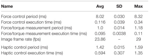
Table 2. Real-time performance statistics.
The force control, haptic control, and force/torque acquisition have two performance measures in Table 2. The first is the period and the second is the execution time, which is the time used to complete the task in one period. The number of domain switches for the force control is two switches per period. For the haptic control, there is one domain switch per period. The frame rate of the ultrasound image is also reported in Table 2.
5.2. Compliance Force Control
For the experiment where the probe is in free air and have a setpoint of zero, the results are is reported in Table 3. The results include the SD of the force and velocity, and the position deviation, for different values of K and KI in equation (3). There is a significant difference between all the SDs of the force Table 3 using p = 0.005. For velocity, there is a significant difference using p = 0.005 between all the SD except for when K = 0.005 and KI is either 0.5 or 0.7.
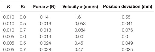
Table 3. The SD of the force and velocity, and the position deviation, measured when force setpoint is zero.
The results for the experiment where the probe is in contact with the phantom and the setpoint changes from 1 to 5 N are shown in Figure 8. The rise time and bandwidth are shown in Table 4.
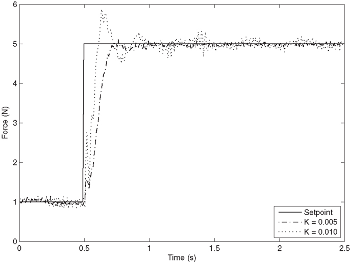
Figure 8. Force response in the z-direction with KI = 0.7.
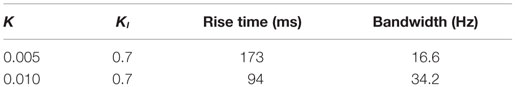
Table 4. Time used from the setpoint is changed until the force is at 90% of the setpoint, and bandwith of the controller.
The results for the experiment investigating the effect of the joint velocity limitations are shown in Figure 9, using the parameters K = 0.005 and KI = 0.7, as these parameters gave a good compromise between a responsive controller and small oscillations. All joints are limited by qdl, which is specified in rad/s. The bandwidth of the force controller is 7.0, 12.5, and 15.5 Hz for qdl 0.05, 0.1, and 0.2, respectively.
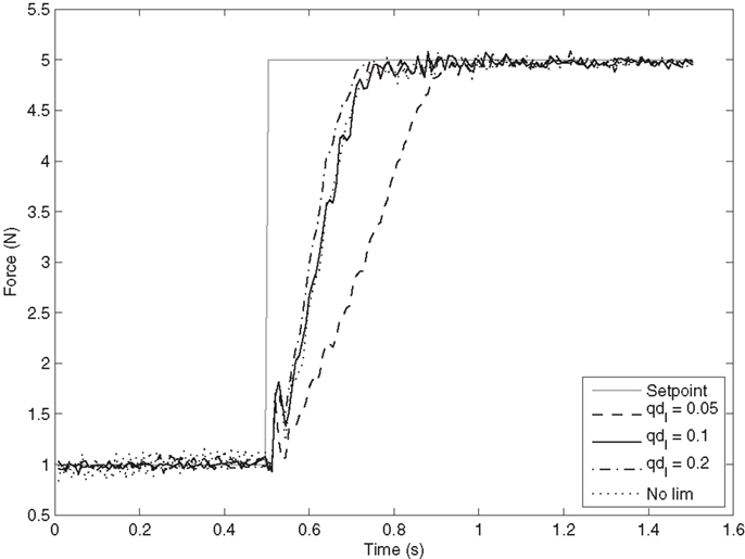
Figure 9. Force response in the z-direction when joint velocities are limited. qdl is the limitation applied to all joint velocities in rad/s. K is set to 0.005 and KI to 0.7.
5.3. Forward Flow Haptic Control
In Figure 10A, the master and slave positions are given. The positions are transformed into the same reference for comparison. The bandwidth for the position control is estimated to be 65.4 Hz. In Figure 10B, the rotation velocity of the master and slave are shown. In these two figures, the reference signals are sent from the master to the slave. However, the force is sent from the slave and to the master. Figure 10C shows the force measured at the slave and master, and the bandwidth of the force controller at the master is estimated to be 13.4 Hz.
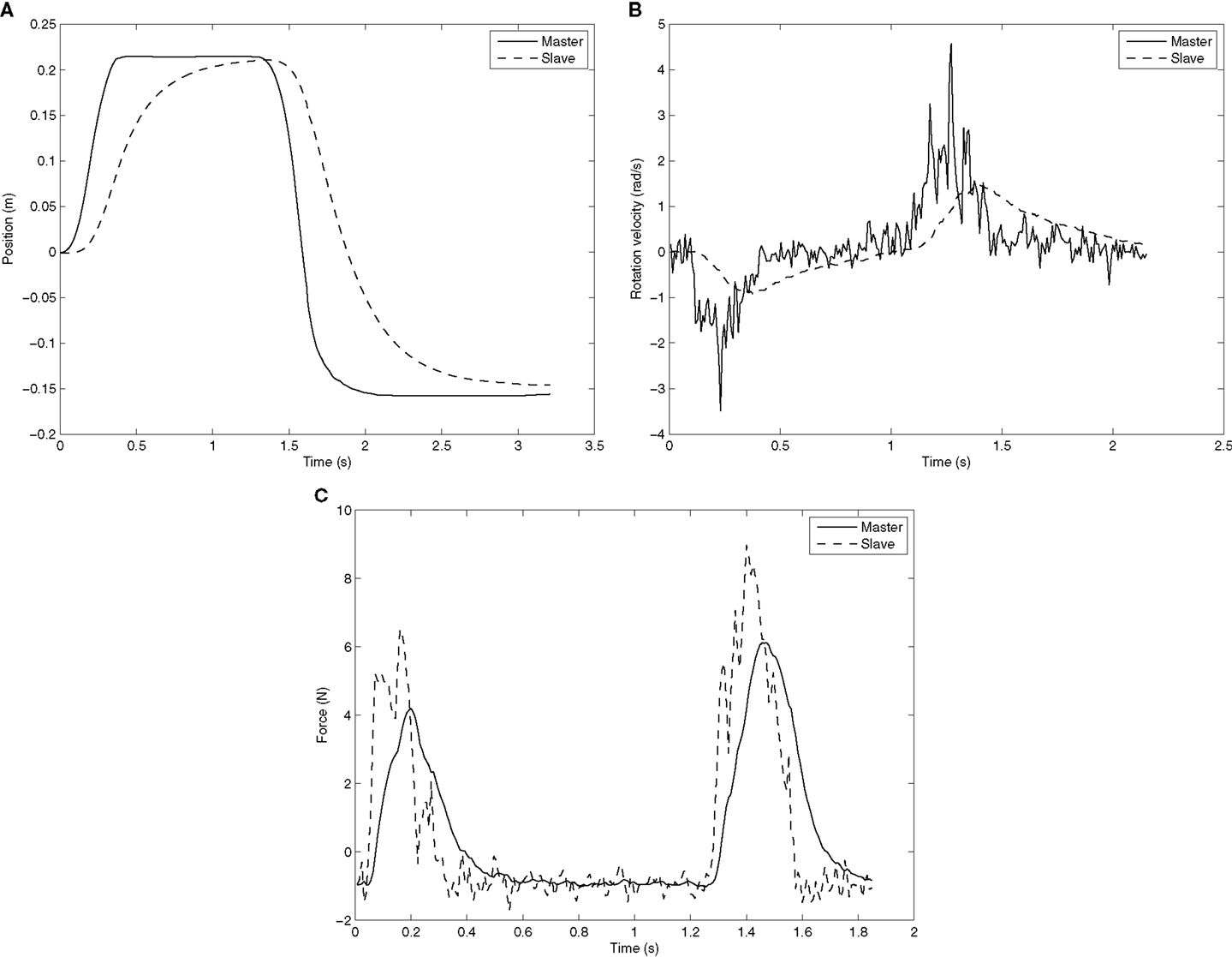
Figure 10. Master and slave position, rotation velocity, and force. Each subfigure is a separate experiment. (A) Master and slave position when the master creates a step-like input. (B) Master and slave rotation velocity when the master creates an impulse-like input. (C) Master and slave force when the master creates an impulse-like input.
The transparency bandwidth of the controller is 39.5 Hz and the controller has good transparency up to 1.2 Hz. The definitions of transparency and good transparency were given in Section 4.3.
5.4. System Compared to the Requirements
Both the requirements found in Section 2 and the actual features are listed in Table 5. Many of the requirements in the table are compared against product specification (Table 5 footnote a–c), and all these requirements are met. In addition, we required that the system should be low cost. The total cost of the system hardware is approximately 31,900$, excluding the ultrasound machine.

Table 5. Comparison of system requirements and actual properties.
The force sensor has a dynamic range of 65 N in the sideway directions and 200 N in the up and down direction. It is the last direction that is important because it is here the largest forces occur. The accuracy is measured as the SD of each individual force channel from the sensor and the maximum of these three are shown in the table.
6. Discussion
Most of the previous efforts in the field either use industrial robots not suited for human interaction or custom-made robots. There are three main advantages in using a collaborative industrial robot as compared to custom-made robots. First, the industrial robot has already been through an ISO certification process for safety, which means that it is not required to have safety guards around the robot, and it can operate directly with humans. ISO is working toward a standard for surgical robots, and once this standard is in place the certification process will be easier. The second benefit is that the industrial robot will have a lower cost as it is produced in larger volumes and production can be streamlined. The system cost is about the same as an ultrasound machine used at a local health-care center, and we believe that this low cost can help it gain widespread usage. The third advantage is that the system can be made commercially available, with less need for further research and development.
This paper presented a general system, as opposed to a custom-made system for a specific clinical application. The goal of creating a general system was that it could then be adapted to several different clinical applications. The creation of a general system does not require formal interviews with physicians before its development. However, a logical next step will be to customize the system to a particular setting and perform user’s studies.
6.1. Real-Time Performance
The force/slave control loop runs at 125 Hz, which means that it should have a period of 8 ms. In Table 2, the period is reported to be an average 8.02 ms, but the most important factor for a real-time system is the maximum period, which is 8.32 ms. This shows that even if the control program enters a non-real-time domain for shorter periods, as described in Section 3.2, the real-time requirements are met. The maximum time used for executing the control algorithm is only 0.34 ms, which means that there is a very large margin from the real-time requirements.
The force/torque acquisition loop should run at 1000 Hz, giving a period of 1 ms. The average period reported in Table 2 is 1.0 ms, the maximum is 1.18 ms. This jitter is acceptable for our application. The actual acquisition takes a maximum of 0.11 ms, which means that there is also a large margin to the real-time requirements.
The frame rate of 23.9 fps is close to the desired 25 fps. There is some jitter on the time between the frames, but the performance is acceptable.
The haptic control should run at 1000 Hz, but is only running at 700 Hz. The frequency is set to a lower value than the requirement because communicating to the haptic device takes up to 1.32 ms, and this would violate the real-time requirements of a 1000 Hz loop. By setting the control loop to 700 Hz, the period should be 1.43 ms, which is the very close to average reported in the experiment. There is a high variation in the execution time for the haptic control loop. This is most likely because the communication with the haptic device takes place outside the real-time domain.
6.2. Compliance Force Control Performance
The force control has been assessed using three experiments. In the first experiment, the probe is in free air and should be stationary; however, noise causes the probe to vibrate. With K set to 0.010 and KI set to 0, the SD of the measured force is 0.14 N (see Table 3). By using the filter, this noise is reduced to 0.016 and 0.018 N for KI 0.5 and 0.7, thus reducing the noise by a factor of more than 8. It is also shown in the table that the robot is drifting away from its starting position when KI is 0 and K = 0.010, but the drift is negligible for the two other cases. This clearly shows that adding the damping term in the control law increases the robustness of the system. The damping also increases the responsiveness of the controller at lower frequencies, and therefore, it is beneficial to have a high KI. For KI = 0.5, the stationary filter gain is multiplied by 2 and for KI = 0.7 by 3.33. The value 0.07 is chosen for KI for high noise robustness and increased gain on lower frequencies.
The second requirement for the force control was that the system should not be underdamped. With a feedback gain of 0.010, the system is clearly underdamped and fails to meet this requirement. With K = 0.005, there is no overshoot, but some small oscillations before entering the steady state. There are some oscillations in the steady state for K = 0.010. This means that K = 0.005 is a good compromise between fast response and avoiding an underdamped system. As the performance of the compliance control is highly affected by the stiffness of the environment, the parameters K and KI might not be optimal on a human body. The ultrasound phantom is soft and is comparable with the soft tissue on the human abdomen, and therefore, the parameters found should give sufficient performance on this type of tissue. However, imaging on a stiffer surface, for instance, between the ribs, will likely require a different set of parameters.
The bandwidth of the force controller was found to be 16.6 Hz, which is much higher than the required 3 Hz. In Pierrot et al. (1999), a graph of the force controller step response of a robotic ultrasound system is reported. Based on the graph, we estimate the rise time of their controller to be 193 ms when going from 0 to 3 N. This is slower than our system.
As a safety feature, the joint velocity may be limited; this will reduce the bandwidth of the robot non-linearly in the Cartesian space. Figure 9 shows the result of different joint velocity limitations for a K = 0.005 and KI = 0.7. As expected, the rise time decreases as the limitations increase. When the joint velocities are limited to 0.2 rad/s, the response is close to the unlimited response. Using a limitation of 0.2 rad/s or higher will therefore give increased safety for the patient and nearly equal performance for the step response case.
6.3. Forward Flow Haptic Control Performance
Three aspects of the haptic control were evaluated by the experiments: the Cartesian velocity, the rotation velocity, and the force. Both the Cartesian and rotation velocity were sent from the master to the slave, while the force was sent from the slave to the master. Figure 10A shows the position of the master compared to the slave. The response from the slave has a small delay and is not as sharp as the master position; however, this does not hamper the user’s ability to operate the slave.
The rotation velocity from the master is relatively noisy, as seen in Figure 10B. The noise from the master is reduced by the integration step at the slave, and therefore, the slave motion is smooth. Although the slave does not follow the master rotation velocity peaks, it is actually beneficial that the peak velocities are reduced at the slave. The slave has a maximum rotation velocity of 3.2 rad/s for each joint. This is set by the producer of the robot and monitored by the robot’s hardware. By smoothing the rotation velocity, this constraint is not violated. The master follows the force given by the slave very accurately, as shown in Figure 10C.
The estimated bandwidth of the position and force controller for the haptic loop is 65.4 and 13.4 Hz, respectively. This is much higher than the required minimum bandwidth of 3 Hz. Good transparency was defined in Section 4.3, and Zandsteeg et al. (2010) reports that their system achieved good transparency up to 0.5, 1, and 6 Hz when in contact with fat, muscle, and the ribcage, respectively. The system reported here has good transparency up to 1.2 Hz when in contact with a soft medium. This is comparable with the results in Zandsteeg et al. (2010). It is the position control loop that is the main reason for not achieving good transparency at higher frequencies. Using a more sophisticated controller rather than the proportional controller might yield good transparency for higher frequencies.
In Santos and Cortesao (2015), a more sophisticated haptic control method for ultrasound systems is presented, which estimates the environment stiffness online. This approach has good performance regardless of the stiffness of the environment. The approach presented in this paper will have varying performance depending on the stiffness of the environment. A haptic control scheme using two impedance controllers is presented in Koizumi et al. (2009). The paper states that having two impedance controller yields faster position response, compared to having impedance control only at the master site and position control at the slave site. The controller used in this paper is likely most similar in performance to the baseline controller used in Koizumi et al. (2009). The controller presented in this paper has the ability to start and stop the tele-operation without aligning the master and slave robot to a common position. This is an advantage compared to two controllers presented above as the movements of the haptic device do not have to be mirrored by the robot at all times. This would enable the physician to reposition the haptic device to a better pose or temporarily stop the examination.
6.4. Safety
Safety is an important aspect in making a robotic ultrasound system. Although a number of safety mechanisms have been implemented, the idea of being examined by a robot may make the patient feel anxious. By giving the patient some degree of control over the robot, anxiety may be reduced. In this paper, we have an emergency stop button that the patient can use if they feel discomfort or want to stop the robot for other reasons. Also, robots are being used in more domains as the technology advances; therefore, we believe acceptance of robotic systems in health care will increase in the future.
One should also consider which group of patients to target first. For instance, pregnant women are a group that are generally afraid of large forces toward the abdomen and fetus and would probably make a poor initial group. If pregnant women were the target group, one should probably design a special system taking this into account, as seen in Vilchis Gonzales et al. (2001). A more well-suited group would be (non-pregnant) patients going for abdominal ultrasound. This area of the body is relatively robust and away from sensitive areas, such as the face and genitals.
Although the robot has built-in safety mechanisms (conforming the requirements given in Section 2.1.1), this is no guarantee for patient safety. The software safety mechanisms described in this paper create an additional layer of safety. When installing the system for use in a clinical setting, a risk analysis should be conducted with a physician. This will identify if there are any risks associated with using the system for a specific medical procedure that are not addressed in this paper. The risk assessment is a requirement in the certification of a collaborative robot.
In the haptic mode, no software safety limitations were given on the joint velocities, as opposed to the force control mode. The primary reason behind this is that when the robot is in haptic mode a human controls the robot and supervises the motions of the slave robot. It is, however, possible to add an additional safety limitation in this mode if this is found necessary when testing the system in a clinical setting.
7. Conclusion
This paper has shown that it is feasible to create a Robotic Ultrasound System using a low cost and commercially available collaborative robot. A set of requirements for such a system has been derived based on the state-of-the-art systems, and our system meets all these requirements. Both the force control and haptic control have been quantitatively assessed. The force control was found to have a faster response than seen in Pierrot et al. (1999), which is a comparable system. Both the force control and the haptic control have a high bandwidth compared to the requirements.
The scope of this study was to verify the technical aspects of a tele-operated ultrasound system. The next natural step will be to use the system in a specific clinical application and to perform user testing. For this stage, it will be crucial to gather additional requirements specific to the clinical setting from physicians, and update the system accordingly. The user interface will also need some improvements in the next stage, to adapt to the workflow of the physicians using the system. In addition, the system needs to be tested in the tele-operation mode over network communication lines in order to assess the usability of the system when latency is present.
Author Contributions
OE and KM designed the study. KM and JF performed the experiments. KM, JF, KG, PH, and OE analyzed the results, discussed additional experiments, and wrote the paper.
Conflict of Interest Statement
The software developed in this project has been licensed to Mektron AS, Norway, which is a supplier of Universal Robots in Norway. There are no other commercial or financial relationships that could be construed as a potential conflict of interest.
The reviewer Yohan Noh and handling Editor Hongbin Liu declared their shared affiliation, the handling Editor states that the process nevertheless met the standards of a fair and objective review.
Acknowledgments
We would like to thank Universal Robots for their help and support in using their robot in this project, and also thank Louise Oram for assisting in editing the English.
Funding
The research leading to these results has received funding from the European Union Seventh Framework Programme under grant agreement no 270396 (I-SUR).
Supplementary Material
The Supplementary Material for this article can be found online at https://www.frontiersin.org/article/10.3389/frobt.2016.00001
References
ABB Robotics. (2015). Available at: new.abb.com/products/robotics
Abolmaesumi, P., Salcudean, S., Zhu, W.-H., Sirouspour, M., and DiMaio, S. (2002). Image-guided control of a robot for medical ultrasound. IEEE Trans. Robot. Autom. 18, 11–23. doi: 10.1109/70.988970
Arbeille, P., Ayoub, J., Kieffer, V., Ruiz, P., Combes, B., Coitrieux, A., et al. (2008). “Realtime tele-operated abdominal and fetal echography in 4 medical centres, from one expert center, using a robotic arm & ISDN or satellite link,” in 2008 IEEE International Conference on Automation, Quality and Testing, Robotics, Vol. 1 (Cluj-Napoca: Institute of Electrical & Electronics Engineers (IEEE)), 45–46.
ATI Industrial Automation. (2014). F/T Sensor: Gamma. Available at: http://www.ati-ia.com
Atkeson, C. G., An, C. H., and Hollerbach, J. M. (1986). Estimation of inertial parameters of manipulator loads and links. Int. J. Rob. Res. 5, 101–119. doi:10.1177/027836498600500306
Bachta, W., and Krupa, A. (2006). “Towards ultrasound image-based visual servoing,” in Proceedings 2006 IEEE International Conference on Robotics and Automation, 2006 (Orlando, FL: Institute of Electrical & Electronics Engineers (IEEE)), 4112–4117.
Boman, K., Olofsson, M., Forsberg, J., and Bostrøm, S. (2009). Remote-controlled robotic arm for real-time echocardiography: the diagnostic future for patients in rural areas? Telemed. J. E Health 15, 142–147. doi:10.1089/tmj.2008.0079
Bruyère, F., Ayoub, J., and Arbeille, P. (2010). Use of a telerobotic arm to perform ultrasound guidance during renal biopsy in transplant recipients: a preliminary study. J. Endourol. 25, 231–234. doi:10.1089/end.2010.0287
Charron, G., Morette, N., Essomba, T., Vieyres, P., Canou, J., Fraisse, P., et al. (2010). “Robotic platform for an interactive tele-echographic system: the prosit anr-2008 project,” in Hamlyn Symposium on Medical Robotics (London).
Courreges, F., Vieyres, P., and Istepanian, R. (2004). “Advances in robotic tele-echography services–the OTELO system,” in Conference Proceedings: Annual International Conference of the IEEE Engineering in Medicine and Biology Society, Vol. 7 (San Francisco, CA: IEEE Engineering in Medicine and Biology Society), 5371.
Courreges, F., Vieyres, P., and Poisson, G. (2008). Robotized Tele-Echography. Berlin: Springer, 139–154.
De Cunha, D., Gravez, P., Leroy, C., Maillard, E., Jouan, J., Varley, P., et al. (1998). “The midstep system for ultrasound guided remote telesurgery,” in Engineering in Medicine and Biology Society, 1998. Proceedings of the 20th Annual International Conference of the IEEE, Vol. 3 (Hong Kong: IEEE), 1266–1269.
De Groote, A., Wantier, M., Chéron, G., Estenne, M., and Paiva, M. (1997). Chest wall motion during tidal breathing. J. Appl. Physiol. 83, 1531–1537.
Dogangil, G., Davies, B., and Rodriguez y Baena, F. (2010). A review of medical robotics for minimally invasive soft tissue surgery. Proc. Inst. Mech. Eng. H 224, 653–679. doi:10.1243/09544119jeim591
Evans, K., Roll, S., and Baker, J. (2009). Work-related musculoskeletal disorders (WRMSD) among registered diagnostic medical sonographers and vascular technologists: a representative sample. J. Diagn. Med. Sonography 25, 287–299. doi:10.1177/8756479309351748
Fjellin, J. E. (2013). Design of a Bilateral Master-Slave System with Haptic Feedback for Ultrasound Examinations. Master’s thesis, Oslo, Norway: University of Oslo.
Goldberg, R., Dumitru, M., Taylor, R., and Stoianovici, D. (2001). “A modular robotic system for ultrasound image acquisition,” in Medical Image Computing and Computer-Assisted Intervention-MICCAI 2001 (Berlin: Springer), 1430–1432.
Gourdon, A., Poignet, P., Poisson, G., Vieyres, P., and Marche, P. (1999). “A new robotic mechanism for medical application,” in Proceedings. 1999 IEEE/ASME International Conference on, Advanced Intelligent Mechatronics (Atlanta, GA: IEEE), 33–38.
Janvier, M.-A., Durand, L.-G., Cardinal, M.-H. R., Renaud, I., Chayer, B., Bigras, P., et al. (2008). Performance evaluation of a medical robotic 3d-ultrasound imaging system. Med. Image Anal. 12, 275–290. doi:10.1016/j.media.2007.10.006
Janvier, M.-A., Soulez, G., Allard, L., and Cloutier, G. (2010). Validation of 3d reconstructions of a mimicked femoral artery with an ultrasound imaging robotic system. Med. Phys. 37, 3868–3879. doi:10.1118/1.3447721
Koizumi, N., Warisawa, S., Hashizume, H., and Mitsuishi, M. (2004). Dynamic switching of a controller based on diagnostic tasks in remote ultrasound diagnostics. J. Robot. Mechatron. 16, 146–154.
Koizumi, N., Warisawa, S., Nagoshi, M., Hashizume, H., and Mitsuishi, M. (2009). Construction methodology for a remote ultrasound diagnostic system. IEEE Trans. Robot. 25, 522–538. doi:10.1109/tro.2009.2019785
Krebs, H., Palazzolo, J., Dipietro, L., Ferraro, M., Krol, J., Rannekleiv, K., et al. (2003). Rehabilitation robotics: performance-based progressive robot-assisted therapy. Auton. Robots 15, 7–20. doi:10.1023/A:1024494031121
Martinelli, T., Bosson, J.-L., Bressollette, L., Pelissier, F., Boidard, E., Troccaz, J., et al. (2007). Robot-based tele-echography – clinical evaluation of the TER system in abdominal aortic exploration. J. Ultrasound Med. 26, 1611–1616.
Masuda, K., Kimura, E., Tateishi, N., and Ishihara, K. (2001). “Three dimensional motion mechanism of ultrasound probe and its application for tele-echography system,” in Proceedings. 2001 IEEE/RSJ International Conference on Intelligent Robots and Systems, Vol. 2 (Maui, HI: IEEE), 1112–1116.
Masuda, K., Takachi, Y., Urayama, Y., and Yoshinaga, T. (2011). Development of support system to handle ultrasound probe by coordinated motion with medical robot. Conf. Proc. IEEE Eng. Med. Biol. Soc. 2011, 4519–4522. doi:10.1109/iembs.2011.6091120
Mebarki, R., Krupa, A., and Chaumette, F. (2008). “Image moments-based ultrasound visual servoing,” in IEEE International Conference on Robotics and Automation (Pasadena, CA: Institute of Electrical & Electronics Engineers (IEEE)), 113–119.
Mitsuishi, M., Warisawa, S., Tsuda, T., Higuchi, T., Koizumi, N., Hashizume, H., et al. (2001). “Remote ultrasound diagnostic system,” in Proceedings 2001 ICRA, IEEE International Conference on Robotics and Automation (Seoul, Korea: IEEE), 1567–1574.
Mustafa, A. S. B., Ishii, T., Matsunaga, Y., Nakadate, R., Ishii, H., Ogawa, K., et al. (2013). “Development of robotic system for autonomous liver screening using ultrasound scanning device,” in IEEE International Conference on Robotics and Biomimetics (ROBIO) (Shenzhen: Institute of Electrical & Electronics Engineers (IEEE)), 804–809.
Naerum, E., and Hannaford, B. (2009). “Global transparency analysis of the lawrence teleoperator architecture,” in IEEE International Conference on Robotics and Automation (Kobe: Institute of Electrical & Electronics Engineers (IEEE)), 4344–4349.
Nakadate, R., Solis, J., Takanishi, A., Sugawara, M., Niki, K., and Minagawa, E. (2010a). “Development of the ultrasound probe holding robot wta-1rii and an automated scanning algorithm based on ultrasound image feedback,” in ROMANSY 18 Robot Design, Dynamics and Control, Vol. 524 (Vienna: Springer), 359–366.
Nakadate, R., Tokunaga, Y., Solis, J., Takanishi, A., Minagawa, E., Sugawara, M., et al. (2010b). “Development of robot assisted measurement system for abdominal ultrasound diagnosis,” in 2010 3rd IEEE RAS and EMBS International Conference on, Biomedical Robotics and Biomechatronics (BioRob) (Tokyo: IEEE), 367–372.
Pierrot, F., Dombre, E., Dégoulange, E., Urbain, L., Caron, P., Boudet, S., et al. (1999). Hippocrate: a safe robot arm for medical applications with force feedback. Med. Image Anal. 3, 285–300. doi:10.1016/s1361-8415(99)80025-5
Priester, A., Natarajan, S., and Culjat, M. (2013). Robotic ultrasound systems in medicine. IEEE Trans. Ultrason. Ferroelectr. Frequency Control 60, 507–523. doi:10.1109/tuffc.2013.2593
Salcudean, S., Bell, G., Bachmann, S., Zhu, W., Abolmaesumi, P., and Lawrence, P. (1999). “Robot-assisted diagnostic ultrasound–design and feasibility experiments,” in Medical Image Computing and Computer-Assisted Intervention-MICCAI99 (Cambridge, UK: Springer), 1062–1071.
Sanderson, C. (2010). Armadillo: An Open Source C++ Linear Algebra Library for Fast Prototyping and Computationally Intensive Experiments, NICTA, Australia.
Santos, L., and Cortesao, R. (2015). “A dynamically consistent hierarchical control architecture for robotic-assisted tele-echography with motion and contact dynamics driven by a 3d time-of-flight camera and a force sensor,” in IEEE International Conference on Robotics and Automation (ICRA) (Seattle, WA: Institute of Electrical & Electronics Engineers (IEEE)), 2931–2937.
Siciliano, B., Sciavicco, L., Villani, L., and Oriolo, G. (2009). Robotics: Modelling, Planning and Control. London: Springer, doi:10.1007/978-1-84628-642-1
Universal Robots. (2010). UR-6-85-5-A Safety Guide Version 1.2. Available at: http://www.universal-robots.com
Universal Robots. (2014). Technical Specifications UR5. Available at: http://www.universal-robots.com
Vieyres, P., Poisson, G., Courreges, F., Merigeaux, O., and Arbeille, P. (2003). The TERESA project: from space research to ground tele-echography. Ind. Rob. 30, 77–82. doi:10.1108/01439910310457742
Vilchis, A., Troccaz, J., Cinquin, P., Masuda, K., and Pellissier, F. (2003). A new robot architecture for tele-echography. IEEE Trans. Robot. Autom. 19, 922–926. doi:10.1109/TRA.2003.817509
Vilchis Gonzales, A., Cinquin, P., Troccaz, J., Guerraz, A., Hennion, B., Pellissier, F., et al. (2001). “TER: a system for robotic tele-echography,” in Medical Image Computing and Computer-Assisted Intervention–MICCAI 2001 (Berlin: Springer), 326–334.
Vilchis-Gonzales, A., Avila-Vilchis, J., Garcia-Torres, A., and Bernal, J. (2007). “A robot for ultrasound examinations,” in IV Latin American Congress on Biomedical Engineering 2007, Bioengineering Solutions for Latin America Health (Berlin: Springer), 693–696.
Vilchis-Gonzalez, A., Avila-Vilchis, J., and Garcia-Torres, A. (2007). “Termi robot,” in Proceedings of the Electronics, Robotics and Automotive Mechanics Conference (Cuernavaca: IEEE Computer Society), 464–469.
Xenomai Project. (2012). Available at: http://www.xenomai.org
Keywords: robotic ultrasound system, compliance control, forward flow haptic control, tele-echography, medical ultrasound robot
Citation: Mathiassen K, Fjellin JE, Glette K, Hol PK and Elle OJ (2016) An Ultrasound Robotic System Using the Commercial Robot UR5. Front. Robot. AI 3:1. doi: 10.3389/frobt.2016.00001
Received: 07 September 2015; Accepted: 18 January 2016;
Published: 05 February 2016
Edited by:
Hongbin Liu, King’s College London, UKReviewed by:
Elena De Momi, Politecnico di Milano, ItalyMohammad Dadkhah Tehrani, Gyeongsang National University, South Korea
Yohan Noh, King’s College London, UK
Copyright: © 2016 Mathiassen, Fjellin, Glette, Hol and Elle. This is an open-access article distributed under the terms of the Creative Commons Attribution License (CC BY). The use, distribution or reproduction in other forums is permitted, provided the original author(s) or licensor are credited and that the original publication in this journal is cited, in accordance with accepted academic practice. No use, distribution or reproduction is permitted which does not comply with these terms.
*Correspondence: Kim Mathiassen, kimmat@ifi.uio.no