The ArmarX Statechart Concept: Graphical Programing of Robot Behavior
 Mirko Wächter
 Simon Ottenhaus
 Manfred Kröhnert
 Nikolaus Vahrenkamp
 Tamim Asfour
- High Performance Humanoid Technologies Lab (H2T), Institute for Anthropomatics and Robotics (IAR), Karlsruhe Institute of Technology (KIT), Karlsruhe, Germany
Programing sophisticated robots, such as service robots or humanoids, are still a complex endeavor. Although programming robotic applications requires specialist knowledge, a robot software environment should support convenient development, while maintaining full flexibility needed when realizing challenging robotics tasks. In addition, several desirable properties should be fulfilled, such as robustness, reusability of existing programs, and skill transfer between robots. In this work, we introduce the ArmarX statechart concept, which is used for describing control and data flow of robot programs. This event-driven statechart approach of ArmarX helps realizing important features, such as increased robustness through distributed program execution, convenient programming through graphical user interfaces, and versatility by interweaving dynamic statechart structure with custom user code. We show that using hierarchical and distributed statecharts increases reusability, allows skill transfer between robots, and hides complexity in robot programming by splitting robot behavior into control flow and functionality.
1. Introduction
Programing complex robots like humanoids is challenging and is often divided into at least two domains. One being, low-level control, which is essential for smooth execution, system stabilization, safety, and consideration of dynamic effects. On the other hand, high-level robot programing copes with perception, task and motion planning, user interaction, memory concepts, and reusability of robot skills. Well-designed robot software frameworks should support the development of complex robot programs on all system levels. Therefore, a framework needs to provide well-defined interfaces for all available robot components and the flexibility to additionally implement application- or task-specific behaviors. In addition, a basic set of robot skills (i.e., robot programs for a special behavior) should be available, which can be used to assemble more complex robot programs. One challenge in building a robot framework is to provide means for doing this in a robust and convenient way.
In this work, we focus on high-level robot programing and discuss how using hierarchical, distributed statecharts for encoding robot skills aid in achieving convenient programing and reusable, transferable robot behaviors. Possible candidates of statechart implementations must meet the following requirements to be considered eligible: full control over data flow and control flow, local scoping of data similar to encapsulation in programing, runtime-reconfigurability as well as runtime introspection. It should also not be necessary to recompile programs upon structural or control flow changes. Furthermore, a graphical user interface is desirable in order to reduce the unavoidable complexity of describing robot behavior and to minimize development and comprehension efforts. This convenience feature should provide means for defining and parametrizing both control and data flow, online visualization of active states and transitions in running programs, and a convenient way to incorporate custom user code. Additionally, a code generator should be provided for enforcing type-safety and catching errors in user code as early as possible as well as allowing source code auto-completion in development environments of statechart-related data types and functions.
We will discuss the statechart concept of the robot development environment ArmarX (Vahrenkamp et al., 2015) in detail and show how it provides both reusability of high-level robot skills realized as distributed, hierarchical statecharts, and the possibility to add user code with access to the external robot components. Figure 1 shows how statecharts are integrated in the basic structure of ArmarX.
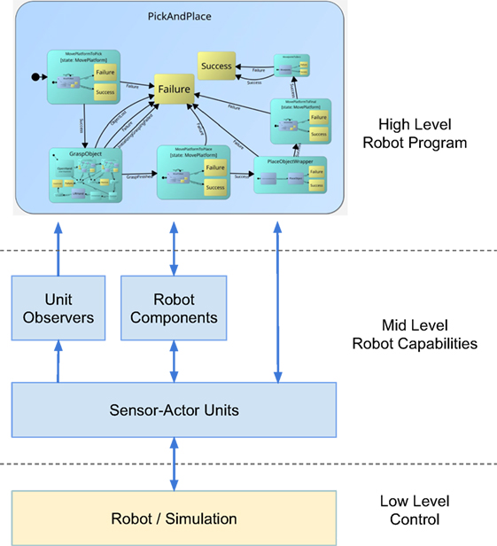
Figure 1. Basic structure of ArmarX. The low-level hardware access is abstracted through the Sensor–Actor unit concept. These Sensor–Actor units realize hardware or simulator access and hide the low-level communication from higher-level layers of the robot software. On the mid-level, robot capabilities, such as perception, planning, and motion generation, are implemented in a network transparent way. The high-level layer comprises a set of robot skills, realized as statecharts, which are used for assembling complex robot programs. The arrows depict middleware communication, which can be local or remote. The decision if a communication channel is local or incorporates remote calls is transparently taken on the fly by the middleware based on the current deployment.
In Section 2, we elaborate on the state of the art and compare it to our approach. Our statechart concept is presented in detail in Section 3. This is extended in Section 4 in regard to usability and integration in the robot development framework ArmarX. In Section 5, we show some use cases for the presented approach to give a better understanding of how it can be utilized. The discussion in Section 6 reflects our experience with the ArmarX statecharts, and Section 7 concludes the paper.
2. Related Work
Robot Development Environments (RDEs) have coevolved with the increasing complexity and capabilities of modern robots. Taking a closer look at recent RDEs, there has been an agreement on the necessity of distributed processing for complex robotic systems [e.g., Scholl et al. (2001), Bruyninckx et al. (2003), Metta et al. (2006), Ando et al. (2008), Quigley et al. (2009)]. Communication in such distributed systems is often performed via middlewares, such as CORBA (2006) or Ice (Henning, 2004). In other cases, specialized middleware systems or messaging protocols have been developed based on task-specific requirements.
2.1. Robot Development Environments
Already several years ago, Schlegel and Wörz (1999) saw the necessity to develop modular and distributed frameworks for complex multi-sensorimotor systems and presented the software framework SmartSoft. Apart from distribution and communication, RDEs differ depending on which part of robot programing they target. For example, MiRPA (Finkemeyer et al., 2007) provides a low-level message-oriented real-time communication middleware. OpenRTM (Ando et al., 2008) is situated on the lower control level and provides a component model with input, output, and configuration interfaces as well as basic execution state machines (inactive, active, error states). MOOS (Newman, 2008) is located on a similar level than OpenRTM and provides a publish–subscribe-based communication and data exchange between MOOS applications via a central database. OpenRDK (Calisi et al., 2008) is also a low-level framework and uses agents as main abstraction, which dynamically instantiate modules-containing functionality. Modules communicate through a blackboard-type mechanism and can access input, output, and parameter data of any other module. YARP (Metta et al., 2006), being used for the iCub robots (Metta et al., 2008), provides low-level communication as a basis for higher-level robot capabilities implemented in the iCub software. Last, ROS (Quigley et al., 2009) and Orocos (Bruyninckx et al., 2003) lean toward the implementation of higher-level system capabilities. In ROS, software modules called nodes span a peer-to-peer network and send messages, whereas Orocos provides an explicit component model and separates the structure of the control system from its functionality.
In 2010, Bischoff et al. (2010) started an initiative to structure and formalize the robot development process by identifying and documenting best practices and refactoring existing components to increase reusability and robustness.
Schlegel et al. (2015) and Thomas et al. (2013) strive in their approaches to divide tasks into different complexity levels to reduce the knowledge required to adapt a robot to new but similar tasks.
A different type of architecture for robot skill specification was proposed by Nordmann et al. (2015). They fuse methods of software design and classical motion primitives to form a model-driven approach for complex motion control architectures.
2.2. Statecharts and Coordination Systems
Besides the original publications (Harel, 1987; Harel and Politi, 1998), there are many other publications (Coleman et al., 1992; Von der Beeck, 1994; Samek, 2002) and software projects (Angermann et al., 2014; EasyCODE, 2015; Yakindu, 2015) on statecharts for a variety of different use cases.
The concept of statecharts as new formalism to represent and describe complex systems was presented first by Harel (1987) and Harel and Politi (1998). The concept extends the finite state machines (FSM) proposed by Gill et al. (1962) to a powerful representation, which significantly reduces the complexity for system developers by introducing several notations features. Like FSMs, statecharts consist in their core of states and transitions between these states and extend FSMs by the following features. The most important addition is the introduction of hierarchically nested states. Harel introduced inter-level-transitions to allow direct transitions into sub-states as well as orthogonality to allow parallel execution of different states at the same statechart level. Moreover, a history-connector was added to provide states with a memory, which store the information about which sub-state should be reactivated when a state is revisited. Condition-connectors control to which subsequent state a transition leads. Finally, each state can be connected to actions being triggered during different phases of the state: entering, leaving, and an action that is executed repeatedly as long as the state is active.
Several general purpose frameworks exist, which can be used to specify the program flow based on statechart mechanisms. In late 2015, the W3 consortium released version 1.0 of an XML statechart notation [ScXML, World Wide Web Consortium (W3), 2015] to establish one format describing Harel statecharts. Similarly, the Object Management Group defined the UML StateMachines notations [Object Management Group (OMG), 2015]. While these specifications mainly focus on general purpose notations of the Harel formalism, the ArmarX statecharts aim at providing a ready-to-use statechart framework in the robotics context.
The well-known de facto extension of C++ Boost (Huber, 2007) contains a subproject called the Boost Statechart Library, which offers a statechart implementation close to the original formalism of Harel. It has the unique feature of specifying the statecharts with C++ templates and achieving compile-time statechart validation. While this is a valuable feature to ensure valid statecharts, it does not fit our requirements. For our purposes, we require runtime-reconfigurability and no recompilation on layout changes as well as runtime introspection, which is difficult to achieve if the structure is specified implicitly with C++ templates. On the side of graphical tools, the statechart graphical modeling tool QM (Quantum Leaps, 2015) provides means for designing and implementing event-driven low-level statecharts for embedded systems with a strong focus on traceability at the code level. The complete statecharts are generated into C++ code, meaning that for statechart structure changes recompilation is necessary. In our statecharts, we aim to generate code only to catch errors in the user code as early as possible and for IDE auto-completion purposes. In Yakindu (2015), another graphical statechart modeling tool is presented, aiming at usability and assistance inside the editor during typing. Though it seems to target low-level statecharts like QM with limited data flow control, which is of high importance in the ArmarX statecharts, as described later.
Statecharts are widely used in robotics to control behavior on a high level (Nilsson and Center, 1973; Merz et al., 2006; Billington et al., 2010; Bohren and Cousins, 2010; Klotzbücher and Bruyninckx, 2012), since they address several of the problems of robotics like state-based control and event-triggered execution. In the well-known RDE ROS (Quigley et al., 2009), an approach called SMACH (Bohren and Cousins, 2010) is employed that focuses on data flow in statecharts. However, scope of data flow in ROS SMACH is handled differently than in ArmarX. In ROS SMACH, a child state can access all data used by its parent state. This not only eases programing because it is easy to operate with data on several levels but also violates the principle of modularity of states and creates implicit data dependencies between states. A state using datafields of a parent state cannot easily be reused in another state, since it depends on the availability of specific datafields in a parent state. Due to this, we do not allow data scopes over several state levels in ArmarX and require explicit mapping of data between state levels. Also, ROS SMACH only supports graphical online visualization of states but does not provide any tool for graphical programing. In many aspects, the statecharts of ArmarX are similar to the restricted Finite State Machine (rFSM) (Klotzbücher and Bruyninckx, 2012) from Orocos (Bruyninckx et al., 2003). However, the statecharts in Orocos focus on coordination of components but offer only very limited support to specify transition-based data flow. They promote the “pure coordination” concept, where the coordination part of the framework should be strictly decoupled from the computation capabilities to avoid unresponsiveness and blocking. This resembles the state-phases of our approach, which are split into coordination and computation phases. Though, to give the developer the ability to easily create critical sections separation of coordination and computation is only encouraged and not enforced in the ArmarX statechart framework.
Stampfer and Schlegel (2014) present an aspect similar to our dynamic structure, where they modify the statechart-formalism to allow for dynamic replacement of states with alternatives from a “robot app store” to increase robustness and reduce complexity. This enables usage of different implementations of a state in the same context, which is usually needed if a different robot should be used. Further, they also provide means for controlling data flow in their statecharts. The main difference to our approach regarding data flow control is that Stampfer and Schlegel (2014) attach data directly to events, while in our approach a transition contains a parameter mapping, which defines the sources to be used to fill a target parameter on triggering of a transition (see Section 3.3.5).
Behavior-based systems [e.g., Arkin (1998), Nicolescu and Matarić (2002), Frank et al. (2012), Paikan et al. (2014)] are another way to specify high-level robot functionality. The most striking difference is that statecharts are state-based, and behavior-based systems are rule-based. This means statecharts have an explicit current state, while behavior-based systems only have an implicit state. Additionally, behavior-based systems are inherently parallel, whereas statecharts are sequential. While behavior-based systems may be closer to behavior of humans or animals, we do not think they scale well for programing purposes. For the developer, an explicit state is easier to comprehend, and it eases the debugging process. Both are vital criteria for software development and maintenance.
2.3. Graphical Robot Programing
When developing high-level software on a robotic platform, it is desirable to configure and connect existing components using a graphical user interface to prevent writing repetitive and therefore error-prone source code. This allows new as well as experienced users to intuitively and efficiently combine mid- and high-level components in order to create a functional system structure. Since writing software is one of the main challenges in robotics for beginners, such as students, Graphical Robot Programing offers a great entry point. It removes the obstacle presented by syntax and control flow of a conventional programing language (Rahul et al., 2014). Graphical software development often combines complexity hiding by connecting modular components on a macroscopic scale with the option to write low-level software, facilitating control tasks on joint level or performing motions in Cartesian space (Pot et al., 2009). Graphical and tabular representations are an accessible way to model system behavior in the context of simulation, validation, and consistency checking of a system design before final implementation (MathWorks, 2015c). Hirzinger and Bauml (2006) are using Simulink (MathWorks, 2015b) in conjunction with MATLAB (MathWorks, 2015a) to graphically model subsystems to later generate executables running on a real-time target. The Microsoft Visual Programing Language (Microsoft, 2012b), as part of Microsoft Robotics Developer Studio (Microsoft, 2012a), proposes developing the complete logic and program flow in a visual development environment as it lowers the bar for beginner programmers. However, we decided to limit the visual development in ArmarX to the definition of structure, used data types, and data flow in our statecharts for the benefit that the user can write unrestricted C++ code. The RDE YARP (Metta et al., 2006) also offers means of graphical programing with the gyarpbuilder (Paikan, 2014), yet on another level. With gyarpbuilder, it is possible to connect continuous input and output data of components graphically and to insert arbitrators in these connections to manipulate data flow easily. RtcLink (AIST, 2015) from the OpenRTM project offers a GUI to operate on RT-Components existing in a network. It can activate and deactivate components as well as connect their ports. It leverages the capabilities of an established IDE by providing the GUI as an Eclipse plugin.
3. ArmarX Statecharts
The complexity of multicomponent systems can be challenging in terms of program and data flow. Hence, only skilled experts are capable of designing and realizing highly connected software systems, as they are needed on humanoid robots. The aim of the ArmarX statechart concept is to reduce such complexity and increase reusability of already created functionality.
With ArmarX, we provide a generic robotics software programing environment, which combines event-driven programing with distributed component-based robot applications. A robot framework in ArmarX consists of several distributed components providing access to sensors and actors (i.e., the hardware), offering computation functionality, and realizing a robot memory system as a common data source for the robot software. On top of these robot components, the ArmarX statechart mechanism can be employed to define the structure of the mid- to high-level robot behavior (i.e., the program flow). In order to gain full flexibility within the robot applications, the programmer can use well-defined entry points to implement user-specific source code. By separating structure from behavior, the task of building new robot software applications can be supported through graphical user interfaces, while maintaining full flexibility on source code level. ArmarX provides means of designing such statecharts textually and graphically with the possibility to link them with user code to perform custom operations. The graphical way is presented in Section 4.1 in detail.
In the following sections, we present the design principles we chose for statecharts in ArmarX and the resulting differences to Harel’s formalism. The details of the ArmarX statechart concept are explained in the remainder of this section.
3.1. Design Principles
Key principles of the ArmarX statecharts are modularity, reusability, runtime-reconfigurability, decentralization, and state disclosure.
• Modularity in our statecharts comes naturally through the individual states and explicitly specified input and output. There is no direct interaction allowed between sub-states of different parent states.
• Reusability is ensured, since every state can be used as a sub-state in any other state and has a specific interface for interaction. The interface is specified with the state parameters like the parameters of a function.
• Runtime-reconfigurability means that a statechart can be defined in configuration files, and that the statechart structure can be changed completely at runtime.
• Decentralization means that a statechart does not need to be resided in one process, but can be spread over several processes and hosts. This enables load balancing and robustness. A crashed distributed state component would not crash the whole statechart but would just create an event for higher layers that this specific state has failed (see Section 5.1, for an example of crash recovery).
• State disclosure means that the current state and all its parameters can be inspected at runtime and logged for future behavior adaptation via a network interface (see Section 4.5).
3.2. Differences to Harel’s formalism
The statecharts in ArmarX differ in several points from Harel’s original formalism. We omitted some of Harel’s features to comply with our design principles and to simplify the statechart design process for the developer. We added one important aspect to our statechart, which is not covered in Harel’s formalism: data flow specification and control during transitions. The hierarchy and condition-connectors are available like in the original statecharts. We do not allow direct inter-level-transitions to not violate the principle of modularity. The history-connector is not available, since it conflicts with the data flow specifications, and to reduce side effects during execution as well as to simplify the comprehension of the current state of the system during introspection. Each entering of a state with the same parameters must provide the same internal state. Orthogonality is currently available only in a smaller scope. Each active state can contain an asynchronous user code function executed in a separate thread. Thus, the different hierarchy levels can run in parallel.
3.3. ArmarX Statechart Internals
Statecharts in ArmarX are organized in groups (see Figure 2). Following the composite pattern, a statechart in ArmarX is a state itself. A state can contain sub-states and transitions between these sub-states. Every state can be nested in another state to construct state hierarchies. Transitions between sub-states are triggered by events. Transitions do not only specify control flow but also data flow by attaching a parameter mapping to each transition. This mapping contains instructions on how to fill the input parameters of the next state. Distribution of statecharts over multiple processes is possible with Remote States, which transparently represent states located in another process.
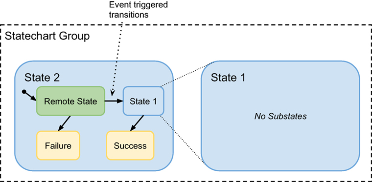
Figure 2. Statecharts in ArmarX are organized in groups. States are comprised of transitions and sub-states. Sub-states are states themselves and can originate from any statechart group. If the statechart groups of parent state and sub-states differ, the sub-state is called a remote state (green state). A state can appear as a sub-state in multiple other states and can even occur multiple times within one state. Control flow is defined by transitions between sub-states. Transitions starting at the current state can be triggered by events. The control flow within a state is terminated if any end-state (yellow state) is reached. The parent state can also be left if an external event occurs.
In the following sections, we are describing the main technical aspects of the ArmarX statecharts: sub-states, transitions, events, state phases, data flow, interfacing with external components, distributed statecharts, and the dynamic statechart structure.
3.3.1. Sub-State Types
Sub-states are not the same as states in ArmarX. States are templates, which are instantiated as sub-states of other states. Though, only one type of sub-states is direct instantiations of states. ArmarX statecharts consists of four different types of sub-states, each with a specific purpose.
3.3.1.1. LocalState
Local states are normal state instances with no special features.
3.3.1.2. EndState
EndStates trigger leaving the parent state immediately. They cannot contain sub-states or execute any user code. EndStates are one way to specify outgoing transitions of the parent state. The name of an EndState specifies the name of the outgoing transition of the parent state.
3.3.1.3. RemoteState
Remote states behave like local states but point internally to a specific state in another process.
3.3.1.4. DynamicRemoteState
Dynamic remote states are similar to remote states but are like generic pointers. On entering, a dynamic remote state morphs into a specific remote state based on parameters mapped during the transition.
3.3.2. Transitions
Transitions in ArmarX statecharts define control flow and data flow. Each transition is associated with one event that the corresponding source state can process. A transition is comprised of a source state, a destination state, the associated event, and a data mapping that defines the data flow between states during this transition.
Each state has exactly one initial transition if the parent state has at least one sub-state. The initial transition can be seen as the transition from the parent state to the first sub-state. This transition is triggered immediately when the parent state is entered. Thus, when the top-level state of a state hierarchy is entered, initial sub-states on each level are entered recursively until the lowest level of the statechart is reached.
Each end-state defines one outgoing transition in the corresponding parent state. When the control flow reaches an end-state, the control flow within the parent state is terminated, and the associated transition of the parent state is triggered.
Transitions do not only describe the control flow but also carry data and define the data flow between states. The data flow during transitions is realized through a parameter mapping definition, which is attached to transitions (see Section 3.3.5). One important detail to mention is that transitions can only be created between sub-states of the same parent state, unlike in Harel statecharts. We decided to create this restriction to keep the modularity principle of states. If states would have transitions to other hierarchy levels or other parent states, the parent state could not be reused without disconnecting that transition.
3.3.3. Events
Transitions between sub-states can only be triggered by events. Events can be fired either by user code, if an end-state is reached, or if a certain condition is met. Events from user code or from end-states are fired immediately, while events from conditions are fired as soon as the condition is fulfilled.
Conditions are specified by terms based on Boolean algebra comprising literals and Boolean operators.
3.3.3.1. Event Generation with Conditions
A literal is defined by a data field of an observer, and a parametrized check that is to be performed on this data field. Conditions are installed in sensor-observers and are evaluated by the appropriate observer after each sensor update. To clarify the concept of distributed conditions, the following listing gives an example that will be explained in detail below.
The first statement in Box 1 defines the literal objectDistance that describes the distance between the hand and object2 and checks if this distance is below 10 mm. object2PoseRef is a reference to the current pose of object2 and is updated continuously. “ObjectMemoryObserver.hand.pose” describes the current pose of the hand within the ObjectMemoryObserver. The poseDistance check compares the position components of both poses and evaluates to true if the distance falls below the provided argument value (here 10 mm).
Box 1. An exemplary definition of an event condition.
Literal objectDistance(“ObjectMemoryObserver.hand.pose”, checks::poseDistance, {object2PoseRef, 10});
Literal forceMagnitude(“ForceTorqueObserver.forces.TCP R”, checks::magnitudeLarger, {5.0});
installCondition(“ObjectReachedEvent”, objectDistance || forceMagnitude);
The second statement defines forceMagnitude, which checks if the force in the right TCP is larger than the given threshold. Both literals are combined using a disjunction. So, if either of both conditions is true, the corresponding event ObjectReachedEvent is fired. The condition is evaluated in a distributed fashion. A central component called ConditionHandler distributes the literals to the appropriate observers. This approach avoids unnecessary transmission of high frequency sensor values, since only changes of the Boolean state of a literal are signaled by the observers. When the Boolean term of a condition evaluates to TRUE, the ConditionHandler fires the associated event. The middleware passes the event to the state that originally installed the condition.
In the context of event processing, the ArmarX state disclosure concept is consistently realized, e.g., by providing an event inspection GUI, as shown in Figure 9. This GUI enables the developer to explore condition trees of currently active conditions, and it further allows inspecting the history of past conditions.
3.3.3.2. Event Processing
Arriving events are queued and processed sequentially by the receiving process. Due to the distributed and asynchronous nature of the software framework, processing of events need to be performed with caution in order to ensure stability and consistency. One aspect that needs to be considered is the fact that a state may already be left when an event arrives. To address this issue, all events contain the id of the destination state.
Additionally, special care needs to be taken to consistently consider parallelism. Since statecharts in ArmarX can be distributed over several processes, events can arrive and be processed in parallel. In order to deal with this situation, the ArmarX statechart framework protects critical sections, allowing concurrent multithreaded access. Such critical sections are the event-processing function (one per statechart level) and the state phases, where the state coordination is performed (see next section for details). Thus, transitions can only be taken once, and states are only entered or exited once.
3.3.4. State Phases
During the visit of a state, different phases are passed through: OnEnter, running, onBreak, and onExit. To enable developers to execute own code in a state, each phase is linked to a user code function, i.e., C++ code. OnEnter, onBreak, and onExit are atomic coordination phases, while running is the computation phase of a state for complex, long-running computations. The order of execution of the phases is as follows: onEnter, running, and then onBreak or onExit. Before entering a state (i.e., phase onEnter), the parameters (explained in the next paragraph) are mapped or set to default values. In the onEnter phase, local variables can be set to be mapped into sub-states or prepared for later phases. When a transition is triggered, the onExit or onBreak phase is entered. Which phase is executed depends on the level where the transition was triggered: as aforementioned, statecharts are hierarchical. Thus, it is possible for a higher state to receive an event, although its sub-states are not finished yet. In this case, the sub-statecharts cannot finish in an expected manner. To give the developer an option to deal with this unexpected behavior, each state provides the onBreak phase. If no behavior is specified for the onBreak phase, the user code function of the onExit phase is executed. When a top-level state received an event, the complete stack of child states needs to exit first. This starts at the leaf-sub-state, a sub-state with no further sub-states, and proceeds up level by level.
Whenever a state is entered, its initial sub-state is entered as well. This means that after executing the onEnter phase of a state, the onEnter phase of the initial sub-state is also executed immediately afterward.
Since the user has freedom of implementation in the coordination phases, she/he is discouraged by warnings if computationally costly code is detected. After entering, the running-phase is launched in its own thread to allow the execution of computationally costly user code without interfering with the coordination. In the default-behavior, the coordination does not wait for the run-function to finish and ignores all results produced by the running-phase after the state was left. During each of these phases, the developer can access different parameter dictionaries in the user code functions, which are explained in the next paragraph.
Although C++ code is difficult to verify, we decided to employ C++, since all our algorithms and most robotics algorithms in general are written in C++.
3.3.5. Transition-Based Data Flow
One important, and to our best knowledge in this extend, unique feature of the ArmarX statecharts is the extensive control of the data flow in the statecharts, which eases accomplishing the modularity and reusability principles. All states are equipped with input and output parameter dictionaries to decouple states from external global data storage. Input parameters are read-only in user code functions and specify all parametrization the state needs for its computations. Output parameters can be set in the user code functions, contain the results of a state, and can be used as source for input parameters of the next state or mapped back to the parent’s local or output parameters.
Additionally, so-called local parameters are provided and accessible for the user code. Local parameters are intended to be used for temporal local storage of parameters that are passed down to sub-states’ input, passed up from sub-states’ output, or passed between different state phases. Once a state is left, all parameters are reset in order to avoid side effects of previous visits.
Each parameter dictionary field consists of a string identifier and a variant data type that can manifest itself into arbitrary types. ArmarX already provides the basic types bool, integer, float, double, and string as well as several types associated with robotics, like vectors, matrices, 3D poses, or probability distributions. If needed, developers can implement new types easily.
These parameter dictionaries are defined by the developer and specify the interface of each state, i.e., which data it needs for execution. Each parameter can be optional, can have a default value,1 and/or can be filled from several sources. We call this parameter mapping. When a state is used, its non-optional input parameters without default values need to be connected with other parameters of the same type. Thus, a parameter mapping for each of these input parameters needs to be created for each state instance. The developer can choose between mappings from the output of a previous state from the same hierarchy level, the input or local parameters of the parent state, or from a parameter attached to the transition-event. Additionally, developers can map values from the output of a state to the local or output parameters of the parent state. Later, when another sub-state needs the calculated value as an input parameter, the local parameter is mapped to that input parameter. For example, generic counter states can be implemented following this pattern, so that counting loop sequences of states can be defined without writing any additional specialized custom code. With this, it is possible to pass data from a sub-state to another state later in the chain more easily. Otherwise, the parameters would need to be mapped from state to state. Figure 3 shows the different types of mappings during transitions.
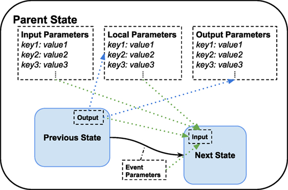
Figure 3. Available types of parameter mapping during transitions. Each state has three parameter dictionaries: input, local, and output parameters. In the blue sub-states, only the relevant dictionaries for the mapping during the transition are shown. The green arrows show possible mappings to the input parameters of the next state. The blue arrows show possible mappings from the output of the previous state to the local and output parameters of the parent state. These mappings happen after leaving the previous state and before entering the next state.
3.3.6. Interfacing with External Components
Statecharts that can only access functionality and data of themselves are not particularly useful for robotics. Therefore, they must be able to access all available components. Since ArmarX is a heavily distributed system, it cannot be assumed that required components are running in the same process or on the same host. Hence, states require network proxies to these components, and it should be ensured that a state is only started if all required components are available. Dependencies for a group of states can therefore be defined in a so-called StatechartContext, which manages dependencies and enables states to communicate with external components.
3.3.7. Distributed Statecharts
Another important feature of ArmarX is the possibility to distribute statecharts over several processes or hosts. To this end, states in ArmarX are organized in groups, which, for example, contain states that are semantically similar and share the same dependencies to external components. In this context, semantically similar means, states that share common aspects regarding their purpose. For example, all states for controlling holonomic platform movements, from a PD-controller to calls to a path planning component, should be encapsulated in one statechart group. Though, this is just a useful convention.
Each group is executed as one component in a so-called RemoteStateOfferer. These RemoteStateOfferers offer states to be used by others states as RemoteStates over the network. For robustness, each RemoteStateOfferer is located in its own process. Thus, a RemoteState is inserted whenever a state uses a state of another group as a sub-state. This process is completely transparent for the developer. The only difference to a local state is that the RemoteStateOfferers name needs to be specified in addition to the state name. Theoretically, each state could have its own group for maximized robustness. Since distributed statecharts are slower than local statecharts, developers need to decide carefully when to split statecharts in more than one group. Another advantage of distributed statecharts is the possibility to deploy them close to their components. A statechart that makes heavy use of the robot’s memory should ideally be located on the same host as the database servers, whereas a visual servoing statechart should be close to the vision system and the host, where joint-level control takes place. Figure 4 depicts the linkage between different statechart groups and RemoteStates.
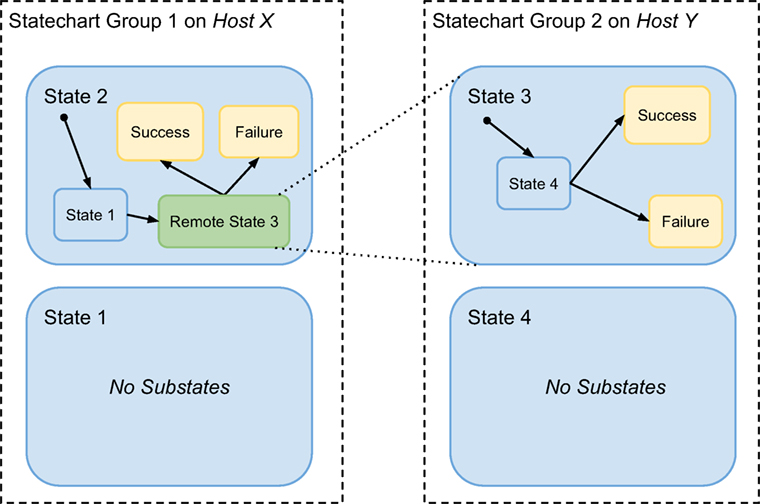
Figure 4. Statecharts in ArmarX are organized in groups, which can be distributed over several processes and hosts. Each statechart group resides by default in one process. By creating RemoteState instances, it is possible to incorporate states of another group transparently into a statechart.
Due to the sophisticated underlying middleware Ice, which transforms network communication into normal, transparent function calls, the step from local statecharts to distributed statecharts was fairly easy. Sub-states pointing to a remote state just use another implementation of the state interface, which reroutes all the function calls over the middleware. On the other side, there is the aforementioned RemoteStateOfferer component, which offers a network interface to the normally, local functions of a state. This way, consistency is assured in the same way as it is done locally, with mutexed access and storage of data only on the offerer side. Thus, synchronization of data is not needed.
3.3.8. Dynamic Statechart Structure
In most statechart frameworks, the structure of the statecharts is fixed, once it has been designed by the developer. This limits the usability of statecharts in a highly dynamic environment, e.g., in the context of humanoid service robots. In this context, a symbolic planner may be incorporated, which needs to be able to change the statechart structure on the fly, according to the currently planned program flow. ArmarX supports dynamic online statechart restructuring by offering so-called DynamicRemoteStates, which provide generic entry points for exchangeable statecharts. As the name suggests, a DynamicRemoteState connects to a state in another (or its own) process. It decides upon entering, into which state it is morphed based on specific parameters passed by the transition. Additionally, it can specify more parameters that are mapped into the connected state. The correctness and completeness of the parameters is verified at runtime, i.e., when the state is loaded.
3.4. Textual Statechart Specification
While the advised method to create statecharts is to use the Statechart Editor (see Section 4.1), it is also possible to specify statecharts textually, as shown in Box 2.
Box 2. An exemplary textual definition of a state.
void defineSubstates()
{
//add sub-states
setInitState(addState < InitialState > (“Initial”));
StateBasePtr finalSuccess = addState < SuccessState > (“Success”);
StateBasePtr finalFailure = addState < FailureState > (“Failure”);
//add transitions
addTransition < Next > (getInitState(), getInitState());
addTransition < TimerExpired > (getInitState(), finalFailure);
addTransition < Success > (getInitState(), finalSuccess);
}
First, each state needs to be added with its state class (TemplateParameter) and the instance name (parameter of addState()). Afterward, transitions between these sub-states can be created by specifying the start and end-state, and on which event these transitions should be triggered.
4. The Statechart Concept Embedded into ArmarX
Statecharts can be implemented in various ways by using a lookup table for transitions, by implementing transition tables via switch-case statements, by implementing an object-oriented state pattern, etc. Since all these approaches are based on writing code to perform the state transitions, a lot of repetitive textual description is usually necessary to define large statecharts. This textual description becomes rapidly incomprehensible for other developers. To overcome this tedious and error-prone work, a graphical statechart editor was developed for ArmarX statecharts.
4.1. Statechart Editor: Defining Control and Data Flow
The goal of the statechart editor is to enable all users to create new statecharts with sub-states, to define input and output parameters, and to connect states with transitions. The editor covers all major use cases related to editing a statechart: creation of structure, definition of control flow, and definition of data flow during transitions. The user is not required to write any custom code to create a functional statechart. We decided to store the statechart definition in a custom xml-based format.
Figure 5A shows the main window of the statechart editor. Statecharts are organized in statechart groups. A statechart group can contain multiple statecharts and sub-states. For further organization of statecharts, folders and sub-folders are available. All statechart groups are listed on the left side of the main window. The user can open any statechart from the state library for graphical editing or reuse a statechart by including it as a sub-state within another statechart.
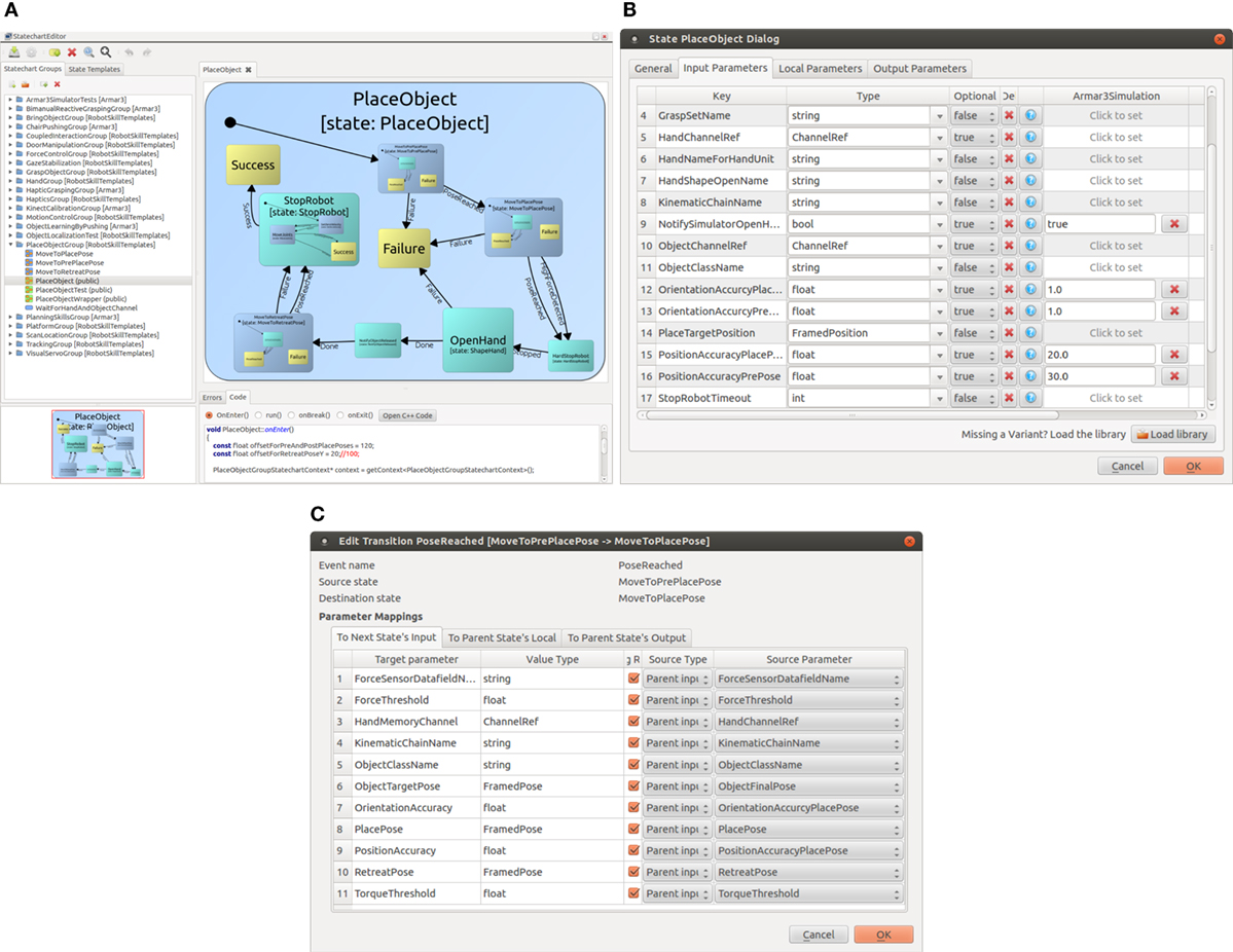
Figure 5. Dialogs of the Statechart Editor. (A) The Statechart Editor is a graphical programming tool to conveniently design the control and data flow of a statechart. (B) The parameters of a statechart including their types and default values are defined in the Statechart Editor. (C) Transitions between states contain a parameter mapping which can be easily specified in the transition dialog of the Statechart Editor.
When a statechart is opened for graphical editing, it is displayed on the right side of the editor. The editor offers a variety of options to edit a statechart, including specialized dialogs and context menus.
4.1.1. Sub-States
By dragging a statechart from the statechart library into the right editing area, a sub-state is created. A state can be reused multiple times as a sub-state within a statechart. The editor displays sub-states in two different colors: states from within the same statechart group are colored blue; states from different statechart groups are displayed in turquoise (RemoteState). DynamicRemoteStates are violet.
4.1.2. End-States
End-states are special sub-states, which are colored yellow. Each end-state implicitly creates an outgoing event/transition. When the statechart transitions to an end-state, the execution within the statechart is terminated. Additionally, the corresponding event/transition is triggered so that control flow moves back to the parenting statechart where execution is continued. When transitioning to an end-state, a statechart completes by terminating its execution entirely if no parenting statechart is present, i.e., the statechart in question is the top-level statechart.
4.1.3. Events and Transitions
As mentioned before, an end-state implicitly creates an event, which in turn implicitly creates an outgoing transition. When a statechart is initially added as a sub-state, all outgoing transitions of this sub-state are displayed as detached transitions. Transitions can be connected to other sub-states by dragging them onto the target sub-state. To create a valid statechart, all transitions have to be connected from a source state to a target state. The target state can be another sub-state, end-state, or the source state itself in case of a reflexive transition. When no detached transitions remain, the transitioning behavior of the statechart is fully defined, which implies that no event is left unhandled. Additional events can be specified in the state properties, which are fired from the code directly or on fulfilled conditions.
4.1.4. State Parameters
Each state has a list of input, output, and local parameters. A parameter is defined by its name, data type, and an optional default value. Figure 5B displays the input parameters of the PlaceObjectSkill, as it is used in ArmarX. Role and usage of the three parameter types is similar to those of parameters, return values, and local variables of functions in imperative programing languages.
4.1.5. Data Flow
A transition can be accompanied by several data mappings that define the data flow within the statechart during this transition. The statechart editor does not support global data storage, since global data storage breaks the concept of data encapsulation. Data are only passed between states during a transition. Data can be passed in 6 different ways, as depicted in Figure 3. The editor ensures that only parameters of the same type are mapped, while parameter mappings are edited in the transition dialog. An example is given in Figure 5C.
For many use cases, it is possible to compose a complete statechart by combining the capabilities listed above and by using existing states from the state library. Writing any additional source code in C++ is not required in these cases.
More complex applications may require implementing custom behavior of states using source code. For these cases, the editor offers the option to jump directly into the source code of any state. Additionally, the source code of a state can be viewed in the bottom panel below the graphical editing area (see Figure 5A).
4.2. Linking Implementation and Control Flow
Using a graphical definition for statecharts implies that all parameters, parameter types, parameters mappings, events, and transitions are identified via names. Since states are reusable and do not store any information about previous or following states, all states have to share the same basic interface for passing input and output data. We decided to define this interface using string-Variant maps, as described in Section 3.3.5. Additionally, the state functions OnEnter, Run, OnBreak, and OnExit can be implemented in C++. Since C++ is a statically typed language without reflection, accessing an input parameter would look similar to this:
float myInput = ((FloatContainer*)getInput(“MyValue”))->get();
The resulting code overhead to access input parameters and to write output parameters is substantial, if one takes into consideration that not only basic types but also lists and maps of any data type are supported. Furthermore, the identification of parameters by strings and run time casts can lead to run time errors that could have been detected during the compile time. Instead, accessing an input without self-written overhead code should look like this:
float myInput = getMyValue();
To achieve this type safe and auto-completion friendly interface, we employ a code generator that generates custom wrapper functions to access inputs and outputs. Inside a generated function, the parameter is referenced by name, and necessary casts are applied. Since these functions are generated automatically, access by name and the casts will never lead to run time errors. Instead, all possible errors related to parameter accessing occur at compile time. Detecting these kinds of errors before executing the statechart saves a lot of time during development.
4.3. Connecting Statecharts and ArmarX Components
One of the main aspects of statecharts in ArmarX is to interact with components. Since different statecharts for different tasks often require different sets of components, each statechart depends on a set of components. The statechart editor generates a complete list of all available ArmarX components from component meta information. The user can pick any number of components from this list and add them to the dependencies of the statechart, as shown in Figure 6A. Every selected component can then be accessed inside the states via a proxy object. Also, additional code is automatically generated so that the statechart registers these dependencies within the ArmarX framework before start-up. Then, the dependency resolver in ArmarX ensures that all necessary components are running before the statechart starts execution.
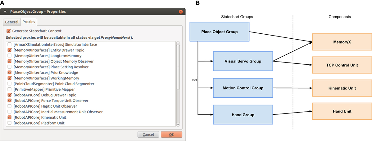
Figure 6. Interaction of Statecharts and Components in ArmarX. (A) Components which are used by statecharts can be selected in the Statechart Editor. This defines the dependencies of a statechart to external components. (B) Statechart groups encapsulating components to reduce interface width on high level statecharts.
The list of component proxies for a state can be interpreted as the interface of this state to the ArmarX framework. Similar to object-oriented development, our goal is to keep these interfaces small. For example, a pick and place statechart requires components to operate the robotic platform, the arms, the hands, do visual servoing, etc. Without encapsulation of proxies, this would lead to a very wide interface for high-level tasks.
To approach this challenge, we offer a wrapping statechart group for each important component. Each state within a group encapsulates a common task of the encapsulated component. For example, the HandGroup offers states to open or close the hands. A high-level statechart can then use these wrapper states to indirectly interact with components without the need of a direct dependency on all components. For example, the PlaceObjectGroup needs to control the arms and hands as well as to perform visual servoing to increase accuracy. This demands interaction with the KinematicUnit, HandUnit, and MemoryX, among others. Each of these units is encapsulated by a statechart group, namely the MotionControlGroup, HandGroup, and VisualServoGroup. The PlaceObjectGroup uses these statechart groups to indirectly interact with the encapsulated components, as shown in Figure 6B.
4.4. Statechart Profiles and State Cloning: Reusing Statecharts for Different Robots
When developing a new skill for a robot, we usually start in simulation. During the transfer of the statechart to the real robot, a lot of parameters usually need to be adapted. For example, when picking up objects from a table, the height of the table might be different in simulation and in reality or the force torque sensor thresholds differ. But, these are just differences in parametrization and not on source code level. Thus, our goal is to have the same source code working in simulation as well as on the real robot.
To meet this requirement, we introduce the concept of profiles. When working with the statechart editor, the user first selects which profile he or she wants to work with. Every parameter of every state can have specialized values in different profiles, but it is also possible to define default values that apply to multiple profiles if no specialized value is set.
Figure 7 displays the parameter edit dialog for the place object example mentioned above. The parameter ObjectName is set to “GreenCup” and is applied in simulation as well as on the real robot. The parameter TableHeight is set to 900 mm for simulation and to 800 mm for the real robot. The statechart will be executed with the appropriate parameters depending on the selected profile.
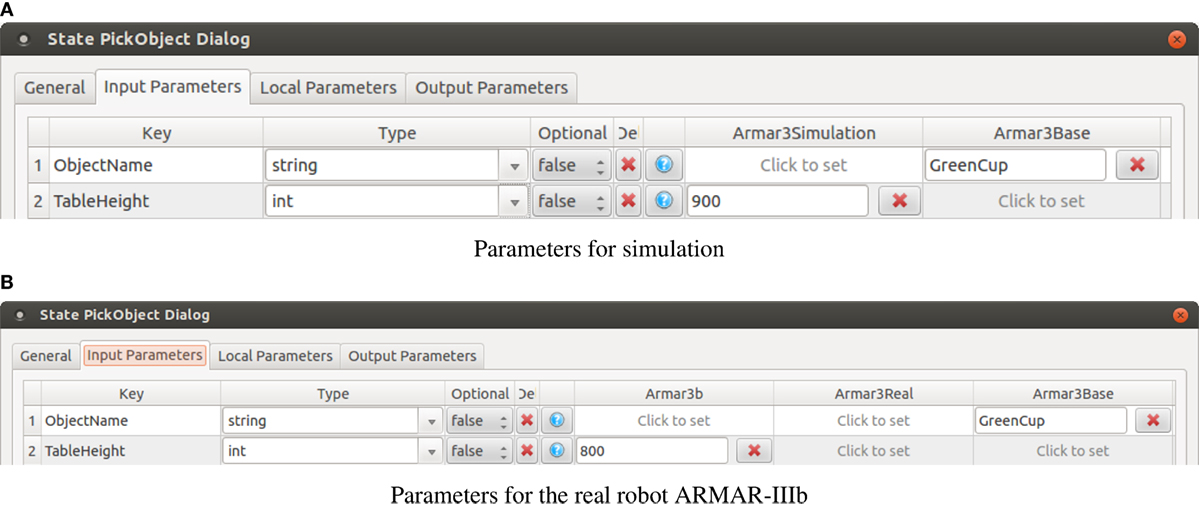
Figure 7. The figure shows statechart profiles for simulation (A), and a real robot (B) to compensate for differences between simulation and robot.
When reusing statecharts for new robots, simple parameter adjustment is often not sufficient. The underlying behavior implementation of states might require adaptation or the statecharts need to communicate with different components altogether. To cover these cases, the statechart editor offers the option of cloning complete statecharts, including all sub-states as well as cloning all state-dependencies of the statechart in question. Dependencies are determined by finding all external statecharts that are used in the statechart to be cloned. This process is applied recursively until the list of dependencies is complete. In addition, the statechart editor checks if some of the dependencies have already been cloned for the target robot and omits these states while cloning accordingly. When cloning states, it is possible to apply a prefix to all new states to avoid later confusion. Additionally, all necessary C++ source code files are copied, renamed, and modified to match the new names. Statecharts yielded by the cloning process can be compiled and executed without any manual adaptations or amending of source code.
Figure 8 shows an exemplary use case, in which the statechart group for placing objects (PlaceObjectGroup) is cloned to be adapted for the iCub robot. In this example, the HandGroup has already been cloned previously and has been adapted for the iCub under the name ICubHandGroup. The editor recognizes that the ICubHandGroup already exists inside the ArmarX iCub package. All newly cloned states that have a dependency to the HandGroup will use the adapted ICubHandGroup instead of the original.
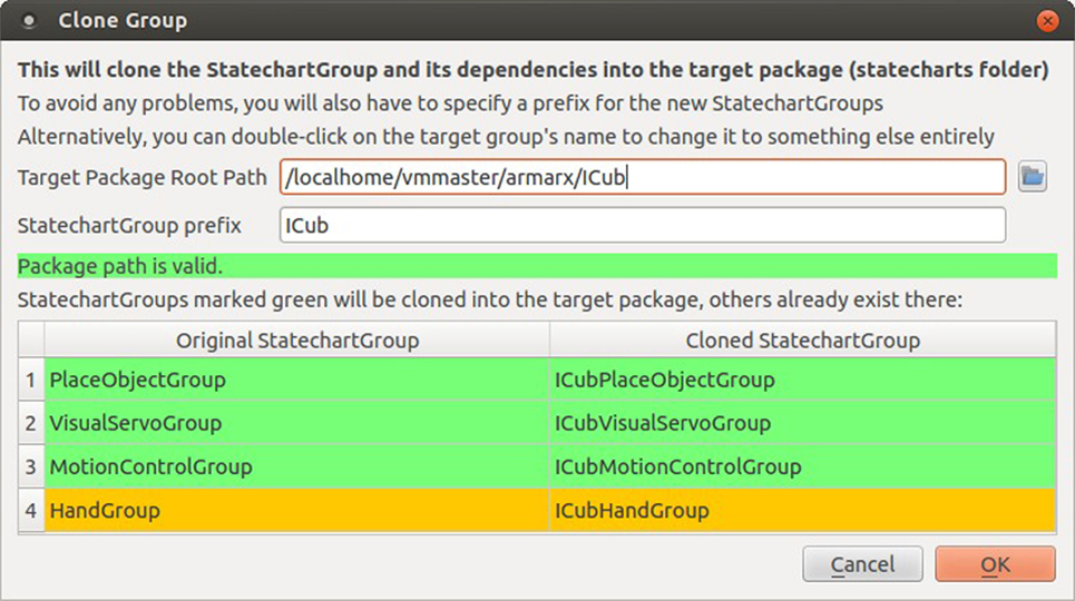
Figure 8. Cloning the PlaceObjectGroup for the iCub.
4.5. System State Disclosure
Disclosing the state of a robotic system is one of the key features of ArmarX for diagnosing problems at runtime and inspecting the internal state during development. Programmers are able to access data of many parts of the system required for debugging, monitoring, and profiling purposes. Different built-in framework mechanisms provide this information, which includes sensor data, conditions, statechart-related events, as well as component dependencies, and the execution state of statecharts and components. Specialized visualizations are available for presenting and inspecting these different aspects. Textual output is presented as a time-stamped log, memory contents are displayed in a 3D view, and a plotter is provided for one dimensional sensor data. Statecharts, their control flow, and active states are visualized in the StatechartViewer (see Figure 10). Within statecharts, conditions are used to generate events based on sensor data and can be viewed as Boolean expression trees, as shown in Figure 9.
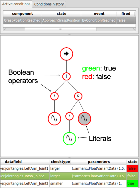
Figure 9. Plugin for visualizing active and already expired conditions based on Boolean terms. The top part of the figure shows available conditions and their origin in respect to components and/or states as well as the corresponding event and its status. In the middle, a visualization of the condition as a binary tree is shown. Each sub-term of the expression tree is colored green upon fulfillment and red otherwise. The leafs of the tree are literals of the condition term. They are Boolean predicates and correspond to the table in the bottom part of the image. Each predicate consists of a datafield, a check-type, and values it is compared to.
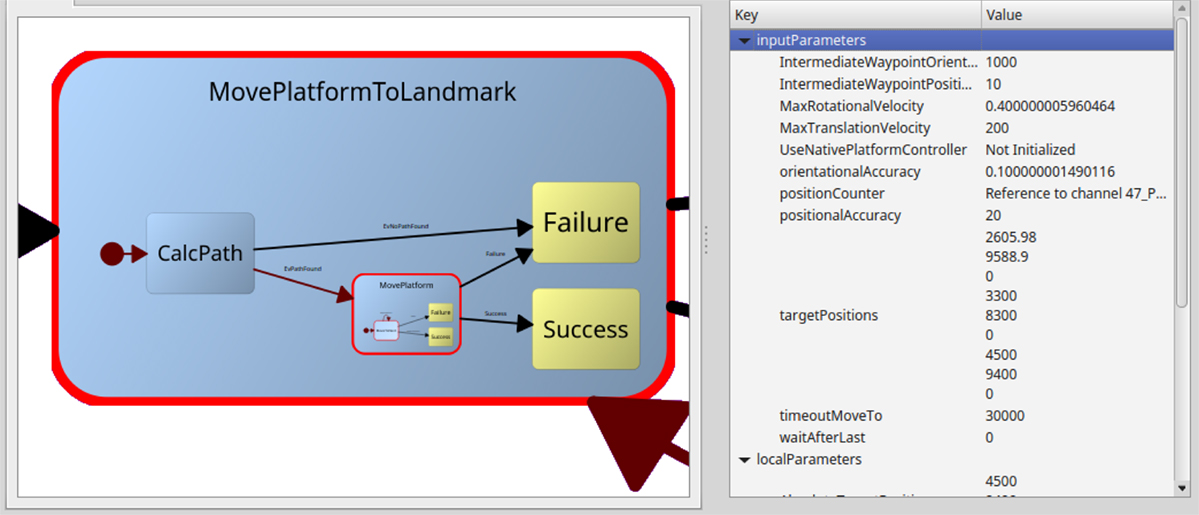
Figure 10. The current state of an executed statechart can be inspected live in the StatechartViewer. The statecharts are layouted on the fly. The red state border signals that this state is active. On the right, current state parameters of the selected state can be examined. Executed transitions are highlighted as well in red, which fades to black over a few seconds to visualize the transition trace.
Additionally, ArmarX discloses the system state on a very low level for determining bottlenecks or providing hints for partitioning the distributed application. On the component level, CPU-, memory-, and network utilization data are accessible via the observer mechanism [see Vahrenkamp et al. (2015)] for easy visualization with the graphical plotter. On the statechart level, state transitions and timing information about state durations are available. To enable later processing and evaluation, this low-level data can be stored persistently in the memory structure provided by ArmarX.
4.6. Validation
Validation is always an important point in software development. Since generic formal validation of a statechart with arbitrary user code is difficult, we supply the possibility to create statechart test cases like unit tests. Since ArmarX statecharts usually interact with robot components, the user can specify a simulation environment that should be started alongside the statechart test. In the statechart test, the output parameters of a state or whole statechart can be validated, or the status of robot components like the memory can be checked.
5. Applications and Use Cases
In this section, several applications and use cases realized with ArmarX will be presented, which show how distributed statecharts support robustness and provide both convenient usage and flexibility.
5.1. Robustness and Fault Recovery
In this use case, we show how fault recovery concepts are realized within ArmarX. This is important, since most robotics software is written in C++, which allows writing program, crashing implementations easily. Hence, a robust robot framework must be able to deal with crashing applications in a way that other components are informed but not affected by a component fault. Further, fault recovery mechanisms should be provided for high- and low-level robot control.
Several concepts support robustness in ArmarX.
• Dependency management: due to the distributed nature of ArmarX, crashing components do not affect other components in a non-deterministic way. If component A depends on another component B, the dependency manager of ArmarX only sets A to the state connected after B is fully initialized and connected. If component B stops working (i.e., crashes), A is informed and reset to its prior initialized state. If the system is capable of restarting B, A will be set to connected again.
• Automatic restart: the deployment mechanisms of the distributed Ice middleware can be used to automatically check for running applications. In case an application (an ArmarX component) stopped working, it can be automatically started again.
• High-level fault recovery: if an implementation of a robot statechart is erroneous and causes the statechart to crash, the encapsulating statechart is automatically informed that the execution of its sub-state resulted in a failure. Hence, the high-level robot program can consistently handle defective parts in the robot program, which could result in a non-deterministic behavior of the robot otherwise.
In the following section, we will show how a crashing sub-statechart can be handled by the robot program. In Figure 11, a statechart is depicted on the left. The execution of the statechart starts with the MainState, which emits the event EvProceed (1 in Figure 11) causing the execution to pass to the CrashingRemoteState statechart (2 in Figure 11). A normal execution would result in a success event (3 in Figure 11), but as shown in Figure 11 on the right, the statechart crashes in a non-deterministic way due to a segmentation fault. Such a segmentation fault results in an immediate termination of the application executing CrashingRemoteState. The encapsulating statechart CrashTestMain automatically gets informed by the ArmarX runtime system via the Failure event (4 in Figure 11) and can recover from this faulty behavior in a deterministic manner (5 in Figure 11).
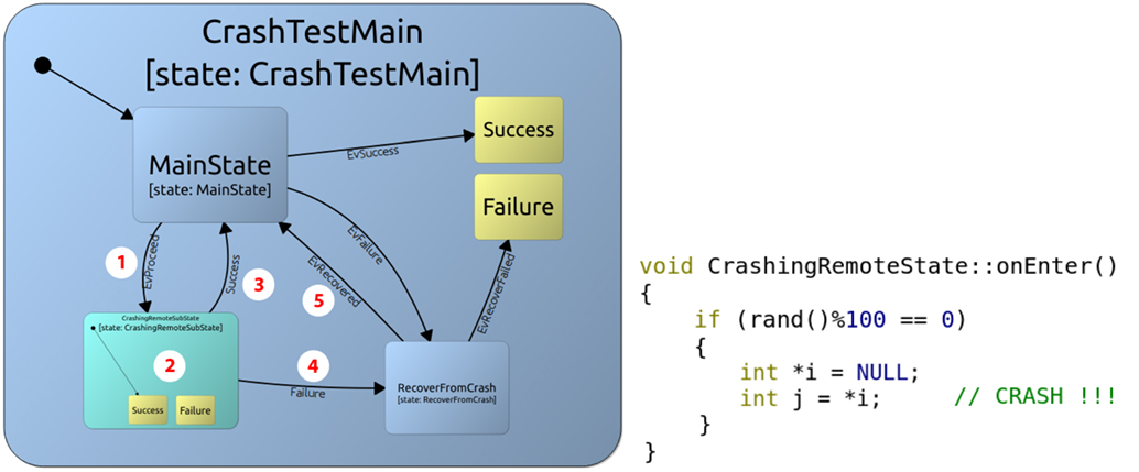
Figure 11. Distribution of statecharts increases robustness of the system. Left: the CrashTestMain state encapsulates a remote sub-state, which faults from time to time due to a segmentation fault. Right: the C++ code of the enter method of the state CrashingRemoteState, which causes a segmentation fault error in a non-deterministic way. The error results in an immediate termination of the application that executes the sub-state.
5.2. Generic Robot Skills
ArmarX provides a library of generic skills, implemented as statecharts, which can be configured and used for a wide variety of robots. The skills cover most basic capabilities needed to setup a robot skill library. In addition to these skills, robot-specific statecharts can be implemented to account for specific features of the platform. The set of generic skills currently provided by the ArmarX framework is listed in Table 1.
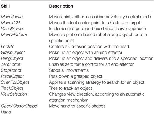
Table 1. Generic set of skills available for use with different robots.
Generic skills can be applied to a specific robot by configuring their parameters and by providing robot-specific components on the mid-level of the ArmarX architecture (see Figure 1). Hence, statecharts provide a dependency list of components, which must be running before execution is possible. For example, the ShapeHand skill needs a HandUnit to be running, and the skill parameters must specify which shapes are available for execution.
5.2.1. Use Case: Generic Skills on Different Robots
To show how skills can be applied to different robots, we present a use case for YouBot (Kuka, 2015) and ARMAR-4 (Asfour et al., 2013), showing the required steps to use the skills MoveTCP and MoveJoints on different robots.
In general, two steps are needed to program a robot platform with ArmarX. First, a basic set of (robot) components must be configured in order to realize the mid-level structure of the robot software, as shown in Figure 1. Second, the initial set of skills has to be configured, defining the basic capabilities the robot programmer can use to build robot applications.
5.2.1.1. Robot Components
Initially, several components must be realized for the different robots. Beforehand, the robot’s visualization, kinematics, and dynamics properties must be defined. In ArmarX, these properties are specified with the Simox (Vahrenkamp et al., 2012) robot file format. The minimal set of components needed for the MoveJoints and MoveTCP skills is listed below:
• KinematicUnit: encapsulates access on joint level. In the following examples, the robots are simulated with kinematic simulation units provided by ArmarX. On a real robot, this component is connected to the robot’s hardware layer. In case of ARMAR-4, the KinematicUnit connects to the ArmarX-RT layer to communicate with the motors and sensors (Vahrenkamp et al., 2014).
• KinematicUnitObserver: observes the raw joint data in order to trigger events.
• RobotStateComponent: a network transparent representation of the robot used for forward and inverse kinematics.
• TCPControlUnit: allows control of the tool center point (TCP) in Cartesian space.
Access to the real robot (i.e., to the drivers) needs to be implemented via the KinematicUnit component, while all these components are already available in simulation and can be configured for use with a new robot. Hence, a basic framework can be quickly realized by configuring provided ready-to-use components of ArmarX.
5.2.1.2. Robot Skills
Once all components are set up for the specific robot, high-level robot program can be implemented. As a starting point, several skills can be taken from the ArmarX skill template library and configured to be used on the robot. In this example, the MoveTCP and MoveJoints skills are used, and a waving statechart is programed via the Statechart Editor tool. As shown in Figures 12 and 13, the realization can take advantage of the ready-to-use skill library of ArmarX on such different robots as ARMAR-4 and YouBot. In addition, the waving statechart that is used in Figure 13 at the top can be directly executed on the real ARMAR-4, as shown in Figure 13 at the bottom. Such a skill transfer for the complex reactive grasping skill (similar to 3) is also shown in the work presented by Paikan et al. (2015).
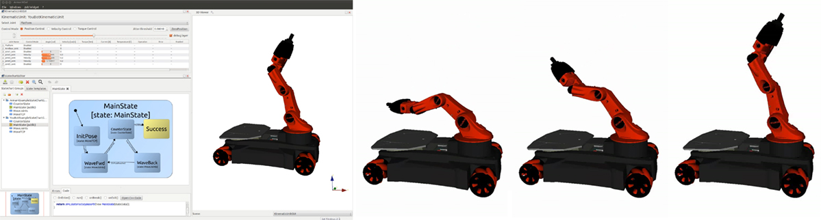
Figure 12. The waving statechart executed on YouBot, while running a kinematic simulation.
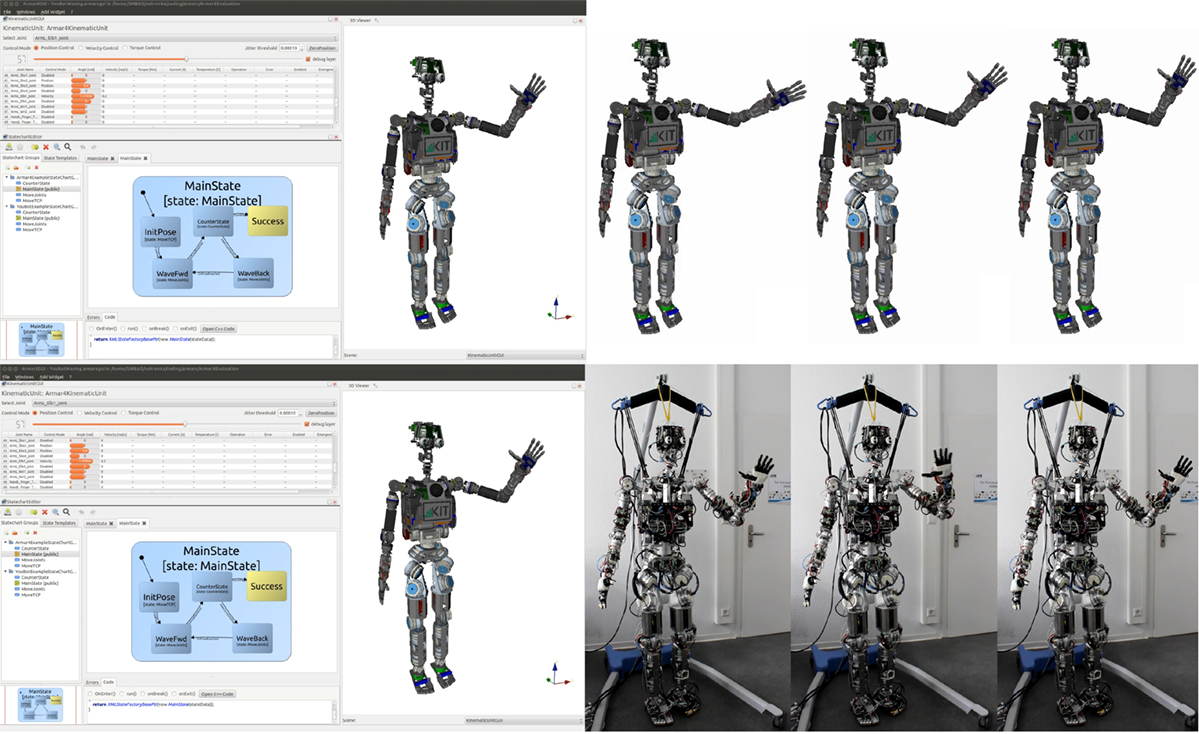
Figure 13. ARMAR-4 executing a waving motion with the same statechart in simulation and on the real robot.
5.3. Reactive Grasping of Unknown Objects
In the context of the Xperience (2011) Project, we developed a statechart and extended accompanying components to perform Reactive Grasping based on vision and haptics on the humanoid robot ARMAR-III (Asfour et al., 2006). This use case demonstrates reusability of ArmarX statecharts through extension of the programed behavior and the incorporation of sensor feedback on different hierarchy levels. The approach presented in Schiebener et al. (2011) was used to initially learn an object hypothesis and pose. The pose and the forward kinematics are not perfectly exact. Therefore, correcting actions during grasping are necessary. Guidance of the hand during the grasping approach phase is based on visual servo. To accommodate for inaccuracies, we need an extended visual servoing that reacts on collisions of the hand with the object. Instead of implementing a specialized version of visual servoing, we created a wrapping statechart called Visual Servo with Collision Detection, which is used in our Reactive Grasping (see Figure 14).
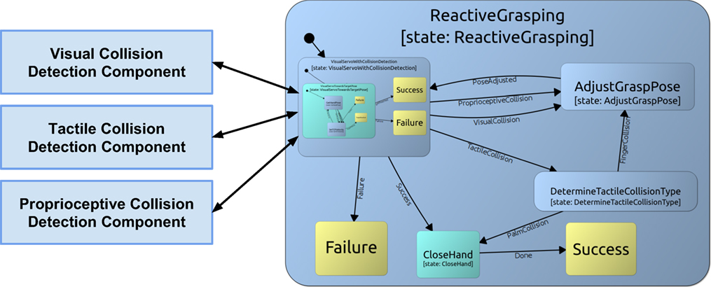
Figure 14. Simplified statechart for Reactive Grasping in the Xperience project.
In parallel to the statechart execution, three different collision detection components are running to detect visual collisions, tactile collisions, and collisions inferred from proprioceptive data. These components run independently, monitor different sensors of the robot, and offer event notifications usable in statecharts. The wrapping statechart Visual Servo with Collision Detection monitors the output of the collision detection components by installing conditions with given thresholds on the output data. Then, the visual servoing statechart is started as a sub-state. If any of the conditions is met during servoing, the appropriate event is fired. The wrapping state Visual Servo with Collision Detection is exited, and the execution of all sub-states is stopped. Hereby, the visual servoing is interrupted, and the collision can be handled appropriately by correcting the grasp pose. After correcting the pose, the statechart transitions back to the extended visual servoing.
By wrapping the visual servoing skill in a statechart, we can reuse and extend the visual servoing without modifying it. The used visual servoing skill is the standard visual servoing from the ArmarX statechart library.
5.4. Dynamic State Replacement
One use case for the dynamic state replacement feature of ArmarX is the combination of a symbolic task planning system with ArmarX statecharts for execution. To connect the planning system to statecharts, a control statechart, as shown in Figure 15, was built around one DynamicRemoteState (depicted in violet). Since statecharts do not offer an interface for remote procedure calls, it is not possible to communicate with states directly. States react on external changes by observing changes in datafields. Thus, we inserted an additional component, the plan step observer, on which the statechart can install conditions to receive an event (EvNextStepPlanned) on changes related to the current planning step. The planning system manages this datafield containing the current action and its parameters. After the event was received, the desired skill statechart is loaded into the DynamicRemoteState and is directly executed. With this powerful mechanism, it is possible to implement interactive and dynamic robotic applications in a consistent and robust way.
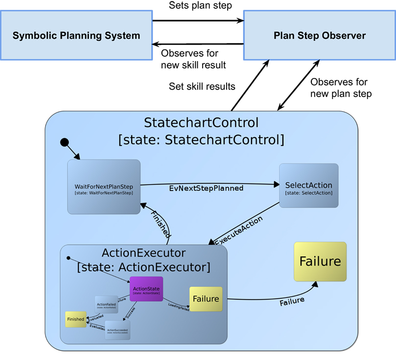
Figure 15. Planning statechart with a DynamicRemoteState (violet) that can be changed at runtime.
6. Discussion
In the following section, we are discussing our experiences with implementing and developing robot programs with the ArmarX statechart framework. Since we realized a large number of robot programs for a wide variety of applications for the robots of the ARMAR series, we gained rich experience that allows us to elaborate on advantages and disadvantages of the proposed concept. The presented statechart approach has extensively been used not only to demonstrate simple tasks like the examples in this paper but also for complex skills applied in real world scenarios, including grasping, opening and closing doors, mixing, or pouring as presented in Ovchinnikova et al. (2015).
We think that the decision to restrict the ArmarX statecharts to a subset of Harel’s original statechart definition has been shown to benefit our statechart concept, since the removed features (inter-level-transitions, history-connector) were rarely missed but improved comprehension and reusability significantly.
Compared to the framework (Scholl et al., 2001) we used before, in which robot behaviors were also encoded by state machines, we see the advantages of now having a clear structure, advanced graphical tools, and a consistent concept for defining the data flow. In particular, the explicit definition of the data flow, i.e., specifying input and output parameters of a state with a defined and clear scope, helps immensely with understanding and reusing existing states. Another effect of this explicit data flow definition is that implicit data dependencies to other states are not possible, which ensures that entering a state with the same set of input parameters leads to the same result. Naturally, specifying the data flow explicitly and in detail is development overhead, but we are sure that it is worth the effort in the long run. Though, specifying and inspecting data flow with graphical tools simplifies this process greatly.
Such graphical tools are not only useful for defining the data flow but also indispensable for developing complex state machines (although ArmarX allows defining statechart structures manually, it is infeasible to realize complex robot programs this way). Hence, the graphical Statechart Editor is one of the most important tools of the ArmarX framework, which supports the convenient development of robot programs.
From our experience, we can confirm the necessity seen by Harel of introducing the concept of hierarchies into state machines. Hierarchies are essential for developing complex state machines and for maintaining reusability. For example, the grasping skill consists of up to six hierarchy levels, where some of the sub-states are used several times. Unrolling this into one hierarchy level results into a statechart that is practically impossible to design due to the number of required states.
The ArmarX statecharts proved to be applicable for use cases from low-level to high-level. An example of a low-level statechart is a controller for holonomic platform movements, where the leaf state is the PD-controller (using the asynchronous user code run-function), and the level above decides on the waypoints. An example for a high-level statechart is the statechart from Section 4, which is used for symbolic plan execution.
Currently, there are many small decider or preparation states, performing some minor, but necessary calculations like coordinate transformations. This introduces clutter, since new states need to be created frequently. In the future, we plan to improve this by the possibility to attach conversion-functions to transitions to perform such minor calculations.
7. Conclusion
We presented the statechart concept of the robot development environment ArmarX and showed how high-level robot programing can be realized in a robust and convenient way. The event-driven statechart approach within ArmarX helps realizing important features, such as increased robustness through distributed program execution, convenient programing through graphical user interfaces, and versatility by interweaving dynamic statechart structure with custom user code. Additionally, we extended the original statechart concept by Harel with the possibility to explicitly specify data flow between states. These features build a solid base for implementing higher-level robot programs, which is accompanied by advanced framework capabilities, such as reusable robot programs and the presented ability to transfer skills to different robots.
In future work, we will improve the framework in terms of high-level robot program development, validation, and debugging. Therefore, we will introduce orthogonality into the statechart concept to enable parallel statechart structures. Currently, parallel execution is supported only between hierarchy levels, but there are use cases where orthogonal skill execution eases the design of a high-level robot program. In addition, we will work on automatic statechart validation in order to eliminate faults in robot programing and to speed up the development process. Furthermore, we plan to offer break points in statecharts, which will greatly improve debugging on statechart level.
Author Contributions
TA identified based on his experience in developing humanoid robots the need for robot software frameworks which link sensorimotor execution and high-level planning. MW and TA developed the proposed statechart concept and MW implemented it in the ArmarX framework. MW, SO, MK, and NV realized the graphical user interface and applications of these proposed statecharts. All authors wrote and revised the manuscript.
Conflict of Interest Statement
The authors declare that the research was conducted in the absence of any commercial or financial relationships that could be construed as a potential conflict of interest.
Acknowledgments
The research leading to these results has received funding from the European Union’s Seventh Framework Programme under grant agreement no. 270273 (Xperience) and from the European Union’s Horizon 2020 Research and Innovation Programme under grant agreement no. 643950 (SecondHands). The authors would like to thank all members and students of the Humanoids group at KIT for their various contributions to this work.
Footnote
- ^Consequently, if parameters have a default value, the optional flag does not make much sense any more, thus these two Boolean flags basically form a tri-state.
References
AIST. (2015). RtcLink. Available at: http://openrtm.org/openrtm/en/content/rtclink-0
Ando, N., Suehiro, T., and Kotoku, T. (2008). “A software platform for component based rt-system development: Openrtm-aist,” in Proceedings of the 1st International Conference on Simulation, Modeling, and Programming for Autonomous Robots, SIMPAR ‘08 (Berlin; Heidelberg: Springer-Verlag), 87–98.
Angermann, A., Beuschel, M., Rau, M., and Wohlfarth, U. (2014). MATLAB-Simulink-Stateflow: Grundlagen, Toolboxen, Beispiele. München: Walter de Gruyter.
Asfour, T., Regenstein, K., Azad, P., Schröder, J., Vahrenkamp, N., and Dillmann, R. (2006). “ARMAR-III: an integrated humanoid platform for sensory-motor control,” in IEEE/RAS International Conference on Humanoid Robots (Humanoids) (Genova), 169–175.
Asfour, T., Schill, J., Peters, H., Klas, C., Bücker, J., Sander, C., et al. (2013). “ARMAR-4: a 63 dof torque controlled humanoid robot,” in IEEE/RAS International Conference on Humanoid Robots (Humanoids) (Atlanta), 390–396.
Billington, D., Estivill-Castro, V., Hexel, R., and Rock, A. (2010). “Modelling behaviour requirements for automatic interpretation, simulation and deployment,” in SIMPAR, Volume 6472 of Lecture Notes in Computer Science (Darmstadt: Springer), 204–216.
Bischoff, R., Guhl, T., Prassler, E., Nowak, W., Kraetzschmar, G., Bruyninckx, H., et al. (2010). “BRICS – best practice in robotics,” in Robotics (ISR), 2010 41st International Symposium on and 2010 6th German Conference on Robotics (ROBOTIK) (Munich: VDE), 1–8.
Bohren, J., and Cousins, S. (2010). The SMACH high-level executive [ROS news]. IEEE Robot. Autom. Mag. 17, 18–20. doi: 10.1109/MRA.2010.938836
Bruyninckx, H., Soetens, P., and Koninckx, B. (2003). “The real-time motion control core of the Orocos project,” in IEEE International Conference on Robotics and Automation (ICRA) (Taipei), 2766–2771.
Calisi, D., Censi, A., Iocchi, L., and Nardi, D. (2008). “Openrdk: a modular framework for robotic software development,” in 2008 IEEE/RSJ International Conference on Intelligent Robots and Systems (Nice: IEEE), 1872–1877.
Coleman, D., Hayes, F., and Bear, S. (1992). Introducing objectcharts or how to use statecharts in object-oriented design. IEEE Trans. Softw. Eng. 18, 8–18. doi:10.1109/32.120312
CORBA, O. M. G. (2006). Corba Component Model 4.0 Specification. Specification Version 4.0. CORBA Object Management Group.
EasyCODE. (2015). EasyCODE. Available at: http://www.easycode.de
Finkemeyer, B., Kröger, T., Kubus, D., Olschewski, M., and Wahl, F. M. (2007). “MiRPA: middleware for robotic and process control applications,” in Workshop on Measures and Procedures for the Evaluation of Robot Architectures and Middleware at the IEEE/RSJ International Conference on Intelligent Robots and Systems (San Diego, CA), 78–93.
Frank, M., Leitner, J., Stollenga, M., Harding, S., Förster, A., and Schmidhuber, J. (2012). “The modular behavioral environment for humanoids and other robots (mobee),” in ICINCO (2) (Rome: Citeseer), 304–313.
Harel, D. (1987). Statecharts: a visual formalism for complex systems. Sci. Comput. Program. 8, 231–274. doi:10.1016/0167-6423(87)90035-9
Harel, D., and Politi, M. (1998). Modeling Reactive Systems with Statecharts: The STATEMATE Approach. McGraw-Hill, Inc.
Henning, M. (2004). A new approach to object-oriented middleware. IEEE Internet Comput. 8, 66–75. doi:10.1109/MIC.2004.1260706
Hirzinger, G., and Bauml, B. (2006). “Agile robot development (ard): a pragmatic approach to robotic software,” in 2006 IEEE/RSJ International Conference on Intelligent Robots and Systems (Beijing: IEEE), 3741–3748.
Huber, A. (2007). Boost Statechart Library. Available at: http://www.boost.org
Klotzbücher, M., and Bruyninckx, H. (2012). Coordinating robotic tasks and systems with rFSM statecharts. J. Softw. Eng. Robot. 3, 28–56.
Kuka. (2015). YouBot Webpage. Available at: http://www.youbot-store.com
MathWorks. (2015a). MATLAB. Available at: http://www.mathworks.com/products/matlab/
MathWorks. (2015b). Simulink. Available at: http://www.mathworks.com/products/simulink/
MathWorks. (2015c). Stateflow. Available at: http://www.mathworks.com/products/stateflow/
Merz, T., Rudol, P., and Wzorek, M. (2006). “Control system framework for autonomous robots based on extended state machines,” in ICAS (Silicon Valley: IEEE Computer Society), 14.
Metta, G., Fitzpatrick, P., and Natale, L. (2006). YARP: yet another robot platform. Int. J. Adv. Robot. Syst. 3, 43–48. doi:10.5772/5761
Metta, G., Sandini, G., Vernon, D., Natale, L., and Nori, F. (2008). “The icub humanoid robot: an open platform for research in embodied cognition,” in Proceedings of the 8th Workshop on Performance Metrics for Intelligent Systems, PerMIS ‘08 (New York, NY: ACM), 50–56.
Microsoft. (2012a). Robotics Developer Studio. Available at: https://msdn.microsoft.com/en-us/library/bb648760.aspx
Microsoft. (2012b). Visual Programming Language. Available at: https://msdn.microsoft.com/en-us/library/bb483088.aspx
Newman, P. M. (2008). Moos-mission orientated operating suite. Mass. Inst. Technol. Tech. Rep. 2299, 1–77.
Nicolescu, M. N., and Matarić, M. J. (2002). “A hierarchical architecture for behavior-based robots,” in Proceedings of the First International Joint Conference on Autonomous Agents and Multiagent Systems: Part 1 (New York, NY: ACM), 227–233.
Nilsson, N. J., and Center, A. I. (1973). A Hierarchical Robot Planning and Execution System. Menlo Park, CA: Stanford Research Institute.
Nordmann, A., Wrede, S., and Steil, J. (2015). “Modeling of movement control architectures based on motion primitives using domain-specific languages,” in Robotics and Automation (ICRA), 2015 IEEE International Conference on (Seattle, WA: IEEE), 5032–5039.
Ovchinnikova, E., Wächter, M., Wittenbeck, V., and Asfour, T. (2015). “Multi-purpose natural language understanding linked to sensorimotor experience in humanoid robots,” in IEEE/RAS International Conference on Humanoid Robots (Humanoids) (Seoul), 365–372.
Paikan, A. (2014). Enhancing Software Module Reusability and Development in Robotic Applications [Dissertation]. Bergamo: Istituto Italiano di Tecnologia.
Paikan, A., Metta, G., and Natale, L. (2014). “A representation of robotic behaviors using component port arbitration,” in 5th International Workshop on Domain-Specific Languages and models for ROBotic systems (DSLRob), Bergamo.
Paikan, A., Schiebener, D., Wächter, M., Asfour, T., Metta, G., and Natale, L. (2015). “Transferring object grasping knowledge and skill across different robotic platforms,” in International Conference on Advanced Robotics (ICAR) (Istanbul), 498–503.
Pot, E., Monceaux, J., Gelin, R., and Maisonnier, B. (2009). “Choregraphe: a graphical tool for humanoid robot programming,” in Robot and Human Interactive Communication, 2009. RO-MAN 2009. The 18th IEEE International Symposium on (Toyama: IEEE), 46–51.
Quantum Leaps. (2015). QM Statemachines. Available at: http://www.state-machine.com
Quigley, M., Conley, K., Gerkey, B. P., Faust, J., Foote, T., Leibs, J., et al. (2009). “ROS: an open-source robot operating system,” in ICRA Workshop on Open Source Software, Vol. 3. Kobe, 5.
Rahul, R., Whitchurch, A., and Rao, M. (2014). “An open source graphical robot programming environment in introductory programming curriculum for undergraduates,” in MOOC, Innovation and Technology in Education (MITE), 2014 IEEE International Conference on (Patiala: Thapar University), 96–100.
Samek, M. (2002). Practical Statecharts in C/C++: Quantum Programming for Embedded Systems. Boca Raton, FL: CRC Press.
Schiebener, D., Ude, A., Morimotot, J., Asfour, T., and Dillmann, R. (2011). “Segmentation and learning of unknown objects through physical interaction,” in Humanoid Robots (Humanoids), 2011 11th IEEE-RAS International Conference on (Bled: IEEE), 500–506.
Schlegel, C., Lotz, A., Lutz, M., Stampfer, D., Inglés-Romero, J. F., and Vicente-Chicote, C. (2015). Model-driven software systems engineering in robotics: covering the complete life-cycle of a robot. Info. Technol. 57, 85–98. doi:10.1515/itit-2014-1069
Schlegel, C., and Wörz, R. (1999). “The software framework SMARTSOFT for implementing sensorimotor systems,” in Intelligent Robots and Systems, 1999. IROS’99. Proceedings. 1999 IEEE/RSJ International Conference on, Vol. 3 (Kyongju: IEEE), 1610–1616.
Scholl, K.-U., Albiez, J., and Gassmann, B. (2001). “Mca-an expandable modular controller architecture,” in 3rd Real-Time Linux Workshop.
Stampfer, D., and Schlegel, C. (2014). Dynamic state charts: composition and coordination of complex robot behavior and reuse of action plots. Intell. Serv. Robot. 7, 53–65. doi:10.1007/s11370-014-0145-y
Thomas, U., Hirzinger, G., Rumpe, B., Schulze, C., and Wortmann, A. (2013). “A new skill based robot programming language using uml/p statecharts,” in Robotics and Automation (ICRA), 2013 IEEE International Conference on (Karlsruhe: IEEE), 461–466.
Vahrenkamp, N., Kröhnert, M., Ulbrich, S., Asfour, T., Metta, G., Dillmann, R., et al. (2012). “Simox: a robotics toolbox for simulation, motion and grasp planning,” in International Conference on Intelligent Autonomous Systems (IAS) (Jeju Island), 585–594.
Vahrenkamp, N., Wächter, M., Kröhnert, M., Kaiser, P., Welke, K., and Asfour, T. (2014). “High-level robot control with ArmarX,” in INFORMATIK Workshop on Robot Control Architectures, 1–12.
Vahrenkamp, N., Wächter, M., Kröhnert, M., Welke, K., and Asfour, T. (2015). The ArmarX framework – supporting high level robot programming through state disclosure. Info. Technol. 57, 99–111. doi:10.1515/itit-2014-1066
Von der Beeck, M. (1994). “A comparison of statecharts variants,” in Formal Techniques in Real-time and Fault-Tolerant Systems (Lübeck: Springer), 128–148.
World Wide Web Consortium (W3). (2015). State Chart XML (SCXML): State Machine Notation for Control Abstraction. Available at: https://www.w3.org/TR/scxml/
Xperience. (2011). The Xperience Project. Available at: http://www.xperience.org
Yakindu. (2015). Yakindu Statechart Editor Tools. Available at: http://www.yakindu.org
Keywords: robot software framework, robot programing, statecharts, graphical user interfaces, distributed processing
Citation: Wächter M, Ottenhaus S, Kröhnert M, Vahrenkamp N and Asfour T (2016) The ArmarX Statechart Concept: Graphical Programing of Robot Behavior. Front. Robot. AI 3:33. doi: 10.3389/frobt.2016.00033
Received: 03 December 2015; Accepted: 03 June 2016;
Published: 23 June 2016
Edited by:
Jochen J. Steil, Bielefeld University, GermanyReviewed by:
Ali Paikan, Istituto Italiano di Tecnologia (IIT), ItalyChristian Schlegel, University of Applied Sciences Ulm, Germany
Copyright: © 2016 Wächter, Ottenhaus, Kröhnert, Vahrenkamp and Asfour. This is an open-access article distributed under the terms of the Creative Commons Attribution License (CC BY). The use, distribution or reproduction in other forums is permitted, provided the original author(s) or licensor are credited and that the original publication in this journal is cited, in accordance with accepted academic practice. No use, distribution or reproduction is permitted which does not comply with these terms.
*Correspondence: Mirko Wächter, mirko.waechter@kit.edu