A Geometry Deformation Model for Braided Continuum Manipulators
 S. M. Hadi Sadati1*
 S. Elnaz Naghibi2
 Ali Shiva1
 Yohan Noh1
 Aditya Gupta1
 Ian D. Walker3
 Kaspar Althoefer2
  Thrishantha Nanayakkara4
- 1Center for Robotics Research (CoRe), Department of Informatics, King’s College London, London, United Kingdom
- 2School of Engineering and Material Science, Queen Mary University of London, London, United Kingdom
- 3Department of Electrical and Computer Engineering, Clemson University, Clemson, SC, United States
- 4Dyson School of Design Engineering, Imperial College London, London, United Kingdom
Continuum manipulators have gained significant attention in the robotic community due to their high dexterity, deformability, and reachability. Modeling of such manipulators has been shown to be very complex and challenging. Despite many research attempts, a general and comprehensive modeling method is yet to be established. In this paper, for the first time, we introduce the bending effect in the model of a braided extensile pneumatic actuator with both stiff and bendable threads. Then, the effect of the manipulator cross-section deformation on the constant curvature and variable curvature models is investigated using simple analytical results from a novel geometry deformation method and is compared to experimental results. We achieve 38% mean reference error simulation accuracy using our constant curvature model for a braided continuum manipulator in presence of body load and 10% using our variable curvature model in presence of extensive external loads. With proper model assumptions and taking to account the cross-section deformation, a 7–13% increase in the simulation mean error accuracy is achieved compared to a fixed cross-section model. The presented models can be used for the exact modeling and design optimization of compound continuum manipulators by providing an analytical tool for the sensitivity analysis of the manipulator performance. Our main aim is the application in minimal invasive manipulation with limited workspaces and manipulators with regional tunable stiffness in their cross section.
1. Introduction
Traditional limitations posed by conventional rigid linked robots, such as vast occupied space, rigidity, and relatively low dexterity, have resulted in an emerging trend during recent years for scientists to show increasing interest in the concept of continuum robots (Hirose and Mori, 2004). Taking inspiration from biological examples such as the octopus arms, chameleon tongues, and elephant trunks, researchers are looking into the possibility of replicating similar maneuverability and grasping characteristics by harnessing the corresponding hyper-redundancy demonstrated in nature (Trivedi et al., 2008). This class of continuum robots promises considerable performance improvements in different areas, which currently witness the presence of traditional robots, such as surgical applications, underwater manipulation, repair, etc. (Jones and Walker, 2006; Mehling et al., 2006; Webster and Jones, 2010; Cianchetti et al., 2013, 2014; Maghooa et al., 2015; Rus and Tolley, 2015). As a natural by-product of this trend, kinematic and static modeling and analysis of these types of robots have gained recent attention within the research community. However, the inherent nature of continuum robots being highly deformable has posed new challenges in this regard (Webster and Jones, 2010).
One of the most common assumptions in continuum robotic research is the Constant Curvature (CC) model, which has been discussed extensively in the research literature. The constant curvature model simplifies the kinematics of a continuum manipulator by assuming that the backbone kinematics in a planar deformed state can be expressed by a constant curvature profile. Webster and Jones (2010) deliver a thorough discussion on this subject in their review paper. Based on the assumption of constant curvature, the authors reviewed several methods for kinematic modeling of continuum robots using two separate sub-mappings: a robot-specific and a general one. The general robot-independent mapping can suffer from singularity, as discussed in investigations such as Godage et al. (2011a), where a new shape function approach suggested by Godage handles this limitation.
Although being commonly used as a simplifying assumption, the constant curvature assumption is usually not valid in the presence of external forces. The exact dynamic models introduced in the literature, which provide better modeling accuracy, can be categorized into four groups: (1) lumped models, using Lagrangian dynamics, which includes a number of rigid-link pieces combined with springs and dampers (Godage et al., 2015). Continuum manipulators can be modeled by extending the lumped model as in Tatlicioglu et al. (2007), where the total kinetic energy is computed by considering an infinite number of rigid sections and replacing the summation over the Lagrangian terms with an integral over the backbone axis; (2) the Principle of Virtual Work (PVW) (Trivedi et al., 2007; Sadati et al., 2016) or simple Euler–Bernoulli beam model (Shapiro et al., 2011) using CC for kinematic maps, where the CC kinematic map parameters are considered to be the model states; (3) Cosserat rod models resulting in a boundary value problem (BVP) that can be solved, e.g., by using numerical methods for solving systems of non-linear equations as in Trivedi et al. (2007) and Godage et al. (2016), or by using a weak-form series solution in a discretized finite element domain as in Tunay (2013); (4) approximate models to identify the system behavior, which construct a setup-specific model using very simple solutions such as a polynomial function (Chen et al., 2009), or more complex solutions such as using series-based shape functions (Godage et al., 2011a).
Each of these methods can be used as a basis for a numerical finite element solution, which is not discussed here (Duriez, 2013; Duriez and Bieze, 2017). The approximate identification-based models, appropriate for real-time control purposes, are more precise in predicting the identified system output and are computationally efficient, but they are only valid for the conditions, input type and input values they are trained for and do not account for the structural characteristics. For example, Godage et al. (2011a) used a horizontally fixed orientation to train the coefficient matrices in their series solution-based model for the kinematics of their setup but did not consider the effect of external loads. Their model is singularity free and provides 95% accuracy for the conditions and inputs they trained their solution for, and the final solution is computationally efficient and faster than lumped model and Cosserat rod models; however, it cannot guarantee accurate results for different orientation and loading conditions than the training assumptions. Simple but less accurate predictions can be made by models based on constant curvature assumptions and be used as a reference for model-based learning, control, and observation of continuum manipulators to enhance the accuracy, generality, and identification time, especially in surgery applications, where observations are limited and less reliable due to limited sensory equipment in the confined space of surgery, lack of accessibility, and general uncertainties related to sensing of a soft tissue (Khadem et al., 2016).
On the other hand, the lumped models and Cosserat rod models suffer from intensive calculations despite being more suitable for design and optimization purposes. The majority of methods, numerical inaccuracy, and singularities in deriving the inverse kinematics are inevitable especially in the case of lumped system models. Additionally, force estimation and control, which are an essential part in aerospace, medical, and human–robot interaction applications, are often hard to implement using the current methods because of their limitations in modeling continuum manipulators’ compound structures. The texture and flexibility of soft robots match well with biological properties. Different mechanisms to control soft robot stiffness for safe interaction and minimally invasive applications are gaining increasing interest recently. To this end, stiffness-tuneable structures by granular jamming (Steltz et al., 2010; Jiang et al., 2012; Ranzani et al., 2015) and low-melting point alloys (Cheng et al., 2014; Alambeigi et al., 2016), morphing structures (Kuder et al., 2013), stiffness controllable interfaces by granular (Follmer et al., 2012; Stanley et al., 2016), layer (Kim et al., 2013), and scale jamming (Hadi Sadati et al., 2015; Santiago et al., 2016) are recently investigated. The new interest in the continuum manipulators with stiffness varying and inhomogeneous compound structures indicates the need for further investigation of their modeling and control problems.
In order to fill the gap between approximate and finite solutions to achieve comprehensive accuracy, as well as computational efficiency, and to constitute a base to model compound and tunable stiffness structure manipulators, we introduced a new geometry deformation-based approach in our previous publication (Sadati et al., 2016). In our previous work, we present an approximate analytical model for compound continuum manipulators with pneumatic braided extensor actuators in the presence of external forces, utilizing experimental observation of the deformed system to model the deformation energy of the continuum media, using the principle of virtual work to account for the behavior of compound structures, and the constant curvature assumption for the deformation of the backbone as an initial but not essential assumption. There, we provided a new way to model pure elongation of pneumatic braided extensile pneumatic actuators using geometry deformation approach. The presented geometry deformation model is based on a famous work by Rivlin (1949) on “the problem of flexure” where he presents a geometrical approach to derive the strain energy function for an incompressible highly elastic cube under pure bending with certain geometrical assumptions about the deformed and initial states.
In this paper, we continue our previous work by presenting an exact yet simpler model for the actuator chamber braid in elongation and bending with two types of braids, a highly deformable and a stiffer braid. A shorter and simpler derivation method is discussed for deformation energy of the continuum media in the planar deformation case compared to the model presented in Sadati et al. (2016). Then, a more realistic solution without the planar deformation restriction is introduced. Finally, two comprehensive models for compound manipulators are discussed; first, by using the principle of virtual energy, Neo-Hookean evaluation of deformation energy, and constant curvature assumption for the backbone deformation; and second, by employing Variable Curvature (VC) kinematics, Hooks linear stress–strain relation, and the Cosserat rod method for general bending of an externally loaded continuum manipulator.
Our approach benefits from implementation of compound structure complexities in the proposed model, i.e., braided chamber and continuum media exact behavior modeling, and accurate estimation of the cross section and backbone deformation by combining geometry deformation and Cosserat rod methods in a simple to derive and efficient to simulate procedure. In comparison, the characteristic parameters of the chambers are not considered in most of the lumped system (Giri and Walker, 2011) and Cosserat rod approaches despite some effort for modeling of the braids in the pure elongation case (Trivedi et al., 2007). An exact model for the cross-section deformation has three main benefits; it increases the modeling accuracy for general design and control applications (discussed in this paper), provides the necessary tool for the trending research on the design of continuum manipulators with tunable regional stiffness (Manti et al., 2016), and enables exact planning for minimal invasive and safe robot–environment interaction applications where the working space is limited, i.e., continuum manipulators in surgery (Cianchetti and Menciassi, 2017) and space applications (Cohen et al., 2016). The need for comprehensive modeling of cross-section deformation of a continuum manipulator has been suggested in Shapiro et al. (2011) too. Our comprehensive modeling tool for compound structures provides a better insight in design, optimization, and control of this class of mechanisms in a simpler, more efficient, and accurate way, which is based on and in agreement with experimental observations. Besides, comparing the accuracy and sensitivity of the models help to understand what level of modeling complexity is needed to incorporate effects of certain structural parameters and achieve a certain accuracy in different applications.
We evaluate our simulation results against experiments on a continuum manipulator with one STIFF-FLOP (STIFFness controllable Flexible and Learn-able manipulator for surgical OPerations) pneumatic actuator module (Cianchetti et al., 2013) shown in Figure 1A having the structural properties presented in Table 1. All the simulations are carried out based on the conditions and inputs of the experiments.
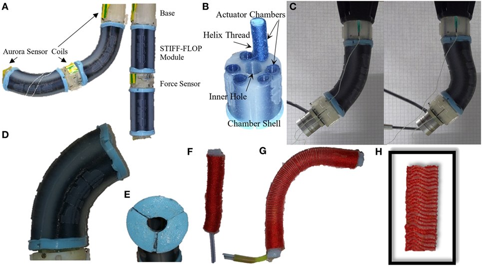
Figure 1. A continuum manipulator with two STIFF-FLOP pneumatic actuator modules. Experiments on one module under body weight load of the next module (A), module structure (B), experiments on one module under extensive external loads (C), a STIFF-FLOP module bending due to pressurization of one pneumatic chamber (D), module cross section deforms from a perfect circular shape when bent (E), a STIFF-FLOP braided extensor actuator (F), the actuator bends instead of pure elongation due to inhomogeneity in the braiding and tube molding (G), the tube cross section decreases and braid folds locally as the chamber elongates because the thread cannot slide on the tube (H).
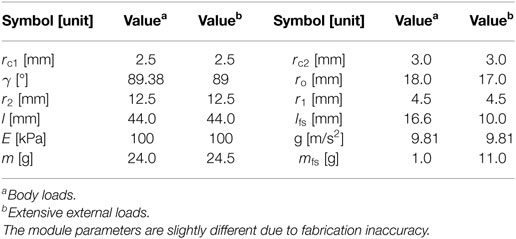
Table 1. STIFF-FLOP parameters for the experiments.
In the following sections, first our experimental method and the setup design are expressed in Section 2, followed by the general description of our modeling framework in section 3. We start with the constant curvature kinematics in section 3.1, the principle of virtual work in section 3.2, and unit deformation energy in section 3.3 as the basis for our first modeling framework. The models for a braided extensor actuator in simple elongation, general elongation, and bending cases are discussed in section 3.4. The geometry deformation method with planar and general assumptions for the cross-section deformation is discussed in section 3.5. Our approach to model compound continuum structures using the constant curvature assumption using the principle of virtual work and the extension of the modeling tool to variable curvature kinematics using Cosserat rod method is explained in section 4. The simulation results and comparison between the models’ accuracy and sensitivity to structural parameters are discussed in section 5. Finally, related discussion and conclusions of this work are presented in sections 6 and 7. While analytic solutions are presented throughout the paper, trapezoidal numerical methods are used for evaluation of the integration as needed.
2. Robot Hardware Design and Experimental Procedure
We use STIFF-FLOP soft actuator modules to validate our modeling approach in this research. A STIFF-FLOP soft actuator module is a three degree of freedom (DOF) pneumatic continuum actuator with three braided extensor actuator chambers placed with an offset from the module central axis and enclosed in a soft body shell shown in Figure 1B (Cianchetti et al., 2013). Soft silicon structures are molded using Ecoflex 50 (tensile strength 2.17 MPa and 100% modulus (E100%) 82.73 kPa from www.smooth-on.com) (Cianchetti et al., 2013). Structural parameters are presented in Table 1. Two different modules have been used for the tests in this paper. They have almost identical dimensions but different active length due to differences in their molding process. Synchronized actuation of the pneumatic chambers causes the module to elongate while asynchronized actuation causes it to bend laterally. The module cross section deforms from a perfect circular shape shown in Figures 1D,E. This occurs because of asymmetric actuation of the pneumatic chambers, inhomogeneity of the module due to molding imperfections, the flexibility of the body shell despite the stiffening of the pressurized pneumatic chambers, and bending of the module. STIFF-FLOP pneumatic actuator chambers are McKibben like braided highly elastic extensile pneumatic artificial muscles threaded helically with an ordinary sewing thread shown in Figure 1F. The thread helix converts radial expansion of the pressurized tube to axial deformation. An extensile chamber, with a braid helix lead angle of more than 54.7°, elongates while a contractile chamber, with a braid helix lead angle of less than 54.7°, shrinks as they are pressurized (Liu and Rahn, 2003; Pillsbury et al., 2016). The thread constraints the radial and axial deformation of the tube while it should be free to slide tangentially. Braids in the well-known “OCT-Arm” series of continuum robots introduced by Pritts and Rahn (2004) are to some extent free to slide tangentially (Trivedi et al., 2007) while they are implanted in the tube silicon body for the STIFF-FLOP. The threads may fold locally if they are constrained tangentially to the body as in the STIFF-FLOP case. A body shell is required to constraint unwanted deformations of the chambers since the inhomogeneity of molding and braiding causes a single chamber to bend randomly instead of pure elongation depicted in Figures 1G,H.
The STIFF-FLOP modules are highly flexible and sensitive to changes in the input pressure. Our tests show good repeatability in their actuation and fast linear response to the input pressure. The molding process guarantees a robust module that can operate for a long time; however, their long-term repeatability has not been investigated yet. The handmade fabrication of the modules results in structural and performance differences. Different volume ratios of the silicone components, air bubbles trapped in the molding process, imperfections in the radial and angular positioning of the twin chambers, and small differences in the active length and active surface area of the chambers due to excessive use of glue to support the caps in some cases results in differences in structural and performance characteristics of the modules. We carried out our tests in this research using two different models of the STIFF-FLOP manipulator that were different in the active length and silicon composition (see Table 1).
STIFF-FLOP module pneumatic actuators are driven by a set of ITV0030-3BS-Q compact pressure regulators (SMC Pneumatic Ltd., Noblesville, IN, USA) connected to a BAMBI MD Range, Model 150/500 pneumatic compressor (Bambi Air Compressors Ltd., Birmingham, UK). A LabView program is designed to feedback control the pressure regulators through USB connection and a USB-6211 DAQmx (National Instrument Ltd., TX, USA) data acquisition board. We used an NDI Aurora (Northern Digital Inc, ON, Canada) tracking system to record the movement of each module tip. We herein present a new modeling approach to facilitate design optimization and real-time simulation of this kind of actuator in the following sections. Two sets of experiments are carried out to validate the simulations and the manipulator tip movement data are recorded.
• One STIFF-FLOP module is randomly pressurized to investigate planar deformation (Figure 1A).
• One module is pressurized in two different steps while excessive external loads at the tip cause large planar deformations (Figure 1C).
3. Modeling Framework
Our approach to modeling of a continuum manipulator consists of a dynamic map (fD), solving the strain translational (ξ) and rotational (ζ) rates based on the internal and external loads, and a kinematic map (fK) finding the manipulator geometry based on the strain rates. The forward and inverse dynamic maps can be found based on various alteration methods; however, some methods are better to evaluate the forward map, while others are more suitable for the inverse map. The continuum form of Lagrange EOM is better for the forward and inverse dynamic maps, the Cosserat rod model is appropriate for the forward static map, and it is more straightforward to derive the inverse static map for a continuum manipulator using the principle of virtual energy (Sadati et al., 2016). Static and quasi-static models are investigated here as special cases of the dynamic model, where the inertial forces are neglected assuming static equilibrium and slow transitions in the system states. This is a reasonable assumption since the application of continuum manipulator in precise manipulation tasks, e.g., minimal invasive surgery as the main application of the outcomes from this research involve less rapid dynamic movements and more quasi-static transition of the states in the task space (Cianchetti and Menciassi, 2017). Hooke’s law of linear stress–strain relation is widely used in the dynamic map (fD), while using Neo-Hookean assumptions and the principle of virtual energy result in a more accurate static map (Gent, 2012).
A constant curvature assumption for simplicity and variable curvature assumption for precise modeling are used to find the kinematic map (fK). The manipulator backbone deformation has been assumed to play the dominant role in the modeling of continuum manipulators, and the cross-section deformation has usually been neglected in the literature. However, as the manipulator becomes softer and the cross-section diameter to the module length ratio increases, the cross-section deformation becomes more important. This cannot be neglected in case of emerging studies on embedding regional stiffness-tunable structures in continuum manipulators (Alambeigi et al., 2016; Meerbeek et al., 2016; Shiva et al., 2016).
Here, we use the principle of virtual energy to model the cross-section deformation caused by constant curvature bending of one manipulator module under general gravitational loads. The use of Neo-Hookean and Hooke’s linear stress–strain relations has been utilized in this case. This method makes modeling of continuum manipulators with compound structures possible and solves the problem directly for the inverse static map , independent of the methods based on Newtonian dynamics such as Cosserat rod theory. Subsequently, we combine our models for the cross-section geometry deformation with the variable curvature kinematics and Cosserat rod theory to find a more accurate forward static map. This model improves the modeling accuracy in the case of having large external forces. For this combined model, we only use the linear Hooke’s law for stress–strain relation.
3.1. Constant Curvature Kinematics
The kinematics of a continuum manipulator used herein is a geometric map for n-modules (fK(n)) between the system state parameters and the manipulator spatial orientation, usually in Cartesian coordinates.
We start with the constant curvature assumption shown in Figure 2A where the manipulator backbone geometry in Cartesian coordinates is given based on the curvature parameters ([κ, ϕ, l], κ = 1/rb) as the system states. This map is expressed in terms of a set of transformations given by Ry(ϕ) − ρtip − Rz(κl) − Ry(−ϕ) (Webster and Jones, 2010),
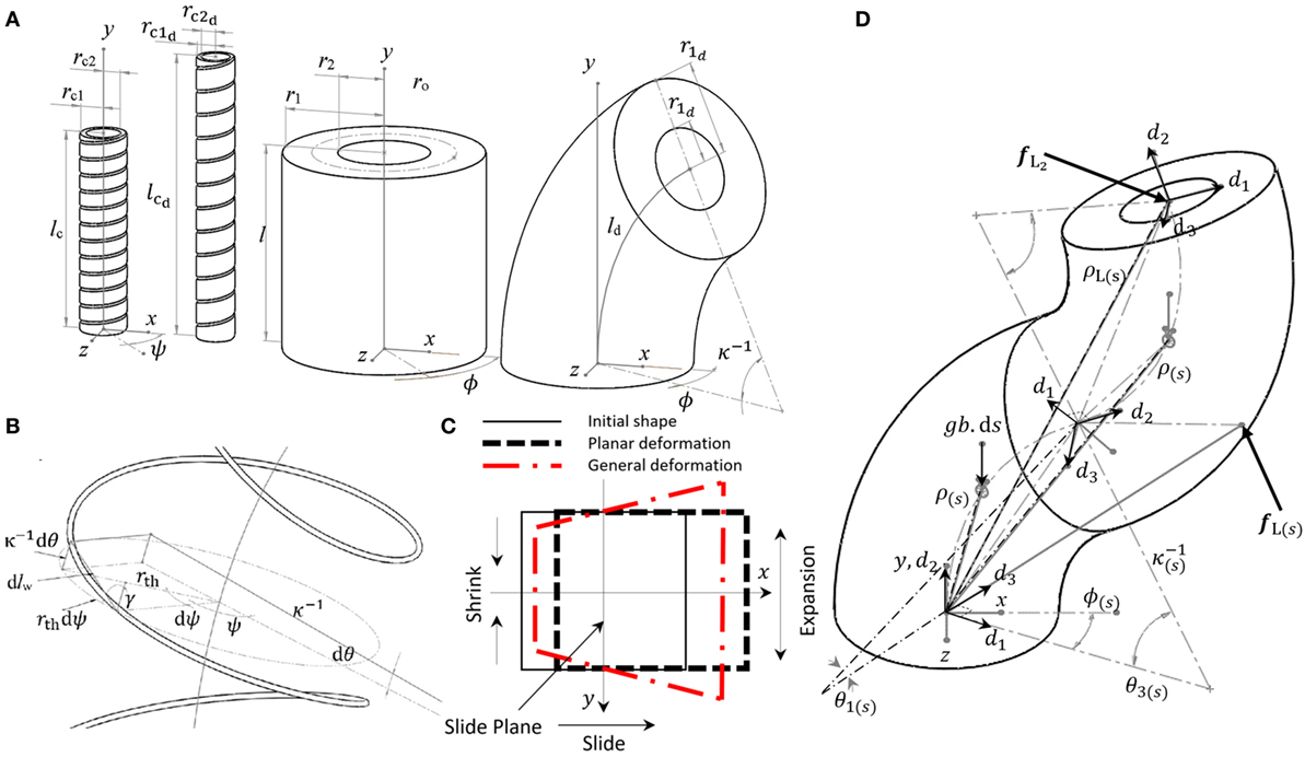
Figure 2. Parameters for elongation and constant curvature bending of a pneumatic actuator and body shell (A), parameters for a bent helix (B), planar and general assumptions for cross-section deformation in elongation–bending based on geometry deformation method (C), and the parameters for the variable curvature kinematics ([ξ, ζ]) and the curvilinear frames (di) expressed by a set of smooth continuous infinitesimal constant curvature segments (D).
The transformation matrix for one module is
where Ry(−ϕ) is added to correct the final cross-section orientation because the module does not actually twist but bends in the direction specified by ϕ. Then, the transformation vector of a point on the backbone with axial location si of the nth module in a manipulator consisting of several modules is , from which the position vector and orientation matrix can be found. For the backbone curve length of the three pneumatic chambers, we have,
We present a variable curvature method as a more accurate solution in section 4.3.
3.2. Principle of Virtual Work
Among all possible changes in the states of a system, the system follows the one set that minimizes the system action (w). This is known as the principle of virtual work or the principle of least action, which can be used to derive the system’s equations of motion (EOM). The summation of all the virtual work in the system maintains an equilibrium described as for rigid body systems and for continuum systems. In the case of STIFF-FLOP manipulator, we have
where is for the point forces (i.e., external loads, body loads, and inertial forces) and δw = δU is for 3D distributed energy fields (i.e., body deformation energy and air pressure work) (Zienkiewicz et al., 1977).
Body loads are distributed forces and moments on the body unit volume, such as the weight. The body load action can be found by integrating the unit action over the volume . It can also be calculated based on the virtual displacement of the load’s center of distribution (center of mass (COM) in the case of the weight). Neglecting the deformation of the manipulator cross section and considering the constant curvature assumption, the COM position vector of the nth module is from the post-multiplication of the traversing modules transformation matrices (Ti(κi, ϕi, li)), a rotation mapping to the bending plane , and local position vector of the curve COM in the bending plane as
Then, for the action, we have . Action for external load (fL) is . For pneumatic pressure action, we have wG = pvG, where vG is the volume in the deformed state and vG is equal to the inner volume of the pneumatic chambers. The pneumatic chamber deformation is constrained with the helical braids and the incompressibility of their shell.
Next, we need to derive deformation action due to the elasticity of the module body and actuator chamber shells.
3.3. Unit Deformation Energy
Elastic deformation action of the continuum media (wE) can be derived with good accuracy based on the Neo-Hookean relation for large deformation (Gent, 2012) using the unit deformation energy as
The unit deformation energy in an orthogonal frame can be derived based on the Cauchy–Green stretch tensor first invariant
in the case that stretch values along the principle axis are known (Gent, 2012), or by having the general deformation map (η) in one coordinate system, we have Rivlin (1949),
Alternatively, (wE) can be found based on Hooke’s linear stress–strain relation law similar to an Euler–Bernoulli beam (Gent, 2012). This is valid for small deformations; however, it can be used in the case of infinitesimal elements along the body, similar to the infinitesimal constant curvature elements in the variable curvature kinematics discussed in section 4.3. Here, the simple Euler–Bernoulli beam stress–strain relations are used by replacing the cross-section moment of area in the local frame based on the deformed geometry as
where and ld are found from the geometry deformation maps. We call this as the Hooke’s law-based model for the body deformation action.
3.4. Braided Extensile Actuator
Braided extensor actuators are threaded continuum chambers similar to McKibben actuators (Tondu and Lopez, 2000) except for the fact that they elongate when pressurized (Liu and Rahn, 2003). The thread constraints the curvilinear axial and radial deformation of the chamber shell but slips tangentially as discussed in section 2.
3.4.1. Simple Elongation
The thread constraint for simple axial deformation is derived from the geometry, assuming that the thread length (sth) and the helix total twist angle (ψ) are fixed (Liu and Rahn, 2003) (Figure 2A).
For the unit length of the thread (dsth which remains constant) in deformed state, we have . Substituting , , , and , where and , we get
A simplified assumption to derive pneumatic pressure action for a STIFF-FLOP module is neglecting the pneumatic chamber thin shell and assuming . Then, we have
This is not valid for manipulators with a thick chamber shell and without an encapsulating body shell, i.e., OCT-Arm (Trivedi et al., 2007). Note that, a single actuator chamber cannot be modeled by having the pneumatic pressure action only.
The typically adopted model in the literature (Liu and Rahn, 2003; Trivedi et al., 2007) assumes that the chamber shell volume is fully constrained to the thread and all the body volume points follow helical radial and axial deformations. We call this method as the constrained volume model. The shell elastic deformation action can be derived based on the incompressibility criteria , , rth = rc, equations (7) and (8) and as the known stretches along the cylindrical coordinate principle axes (Liu and Rahn, 2003; Trivedi et al., 2007). Then, for the actions, we have
For one chamber, using equation (5) and assuming as the only system state, we get (Trivedi et al., 2007)
This assumption constraints the radial and axial deformation of the chamber to the helix, and the chamber tangential deformation is free and can be found based on the incompressibility criteria. A small modeling error is observed because of non-perfect slip between the thread and the chamber surface as indicated by Trivedi et al. (2007). An alternative derivation for a braided chamber with simple elongation is given in the previous work of the authors using geometry deformation method, which results in a more complex solution but with similar simulation results (Sadati et al., 2016). It has been shown that γ is negligible for a dense braid in the case of STIFF-FLOP modules (Sadati et al., 2016) and a simpler result is possible assuming γ ≈ π/2. We can next deduce from equation (12) and can further simplify the problem by assuming a fixed radius case for γ = π/2 and , which suggests that the tube radius does not change and the tube only twists. In the case of fixed radius for equations (14) and (15), we get
3.4.2. Elongation and Bending
The same constraint relation can be derived for a bending helix assuming no twist as shown in Figure 2B to improve the models’ accuracy. The geometrical model for a bent helix is
where . The helix deforms due to the thread cross-section pure torsion (α). We consider any constant curvature elongation–bending deformation as a separate uniform elongation followed by a constant curvature pure bending. The uniform elongation changes γ uniformly, hence from equation (12), we get
where is the variation of the axial length due to elongation, is the deformed radius because of pure elongation, is the helix lead angle after pure elongation, lth = lc/C(γ) is the thread length, which is fixed, and .
In the case of pure bending, we assume B0 as a uniform polar rotational deformation rate on the thread cross section due to external bending moment (τ) on the bent helix (similar to a bending moment effect , where τ is a bending moment, sth is the thread length, and is the polar second moment of area for the thread cross section), the change in the cross-section torsion angle is , where is the thread length element in axial direction and is the deformed helix radius due to pure elongation. Here, and are the stretch ratios caused by pure elongation. Then, the variation of the bending angle along the axis becomes
where is the variation of the axial length due to bending. Using the geometry of the local lead angle (γ(ψ)) and equations (19) and (20), we have
which results in a biquadratic quartic form equation for that can be solved as (Rees, 1922)
where is used to substitute for . This is considered as the exact solution for γ(ψ). This exact model gives complex solutions for B0 and γ(ψ) in the following steps. Therefore, we assume γ(ψ) ≈ π/2 [only in equation (20)], which results in a simpler solution as . Integrating this w.r.t. ψ, we get
where B0 is found from and as
where nth is the number of full turns. Using equations (21), (23), and (24) and substituting for , the simplified solution for γ(ψ) becomes
In initial state, when the helix is straight, the local () and backbone (dlc) axial unit lengths are equal. In the deformed bent state shown in Figure 2B, we have
Similar to equation (12), in the local curvilinear frame, we have
By substituting , equations (25) and (26) in equation (27), we obtain a quadratic function for
The final result is presented in Appendix A.1 due to space limitation. We call this as the exact helix model for .
The exact helix model is valid for stiff threads and springs; however, the softer braids may bend as well as rotate. A simpler result is possible if we assume that the lead angle with the curvilinear axis is constant and equal to the lead angle after pure elongation (γ(ψ) = γe). This model assumes that the thread tends to retain its lead angle and follows the shell deformation without any limitation other than the thread length. From equations (26) and (27), we have
which we call the constant lead angle bending model.
As in the case of pure elongation, actions can be found based on incompressibility criteria , rG = rc1, rth = rc2, equations (7) and (8) as
where the integrals are dealt with numerically in the simulations. The actions depend on κ, hence a standalone relation for one chamber is not derived here. A similar result to equation (13) in the case that we neglect the chamber shell can be derived by substituting with . Assuming a dense thread (γ(ψ) ≈ π/2) does not reduce the complexity of the final solutions in equations (28) and (30) significantly; however, the fixed radius case (γ = π/2), results in a simpler solution for the actions as
An alternative derivation for a bent braided pneumatic actuator is presented based on the deformation geometry approach in the section 3.5.2.
3.5. Geometry Deformation Method
The unit deformation energy for simple pure elongation of a symmetric cylinder is presented in Gent (2012) based on incompressibility criteria and principal stretch ratios. We use equations (7) and (8) and
to derive the unit deformation energy for the pure symmetric elongation case, where λi are the stretch ratios along other principle directors. This can be extended to a simple model for elongation–bending of a cylinder based on equation (26) as
This model accounts for the inhomogeneous elongation of the volume elements but does not consider their bending. We call this as the simple bending model.
We use a similar approach as the solution by Rivlin (1949) for “The problem of flexure” to find a simple but exact analytical solution for the general deformation map of a bent hollow cylinder. We assume that the continuum bodies as an incompressible media and the cross-section plane remains planar under deformation as in the Euler–Bernoulli beam assumption. Therefore, the final orientation of the deformed cross-section plan is determined by the deformation of the backbone. The deformed state for each point consists of the deformation of the backbone in the form of a transformation matrix (Tb) and a vector function presenting the planar deformation of the cross section . Assuming constant curvature, neglecting the pneumatic chamber holes, and dealing with the deformation of each module separately, we have
The deformation map becomes,
where Δθ = y*κ. Incompressibility criteria hold if the determinant of the deformation map Jacobian w.r.t. the initial states (ρ = [x, y, z]) becomes one (Rivlin, 1948),
The above relation is derived and then solved for ρ* following some assumptions on the shape function variable dependency and boundary conditions. Our general assumptions are having a fixed backbone on xz-plane (ρ*(0) = 0), symmetry w.r.t. yz-plane and having the neutral plane along the main axis and perpendicular to the curvature radius ; however, we drop some of these assumptions in different models. We discuss the solution based on two main assumptions.
3.5.1. Planar Deformation
Here, the deformation only occurs in the xy-plane. Assuming no deformation in z direction (z* = z) similar to Rivlin (1949), we can separate the variables as x*(x, z), y*(y), and z*(z). From equation (38), we get
By separation of variables, we have
By integrating for x*, we get
where considering the fixed backbone root, yz-plane symmetry, and neutral plane, we have B1 = B2 = B3 = h1(z) = 0. Then, for I1 and wE from equations (7), (9), and (10), we have
I1 is not a function of y, and the integration for wE is dealt with numerically. From the neutral plane assumption and for the planar elongation–bending deformation case, we get A3 = 1; however, in the case of planar pure bending after a pure elongation, from equation (34), we have , hence . A weak approximate analytical solution is presented in Sadati et al. (2016). The elastic deformation action for the body shell as a hollow cylinder is
3.5.2. General Deformation
A more realistic model can be derived based on a more general assumption for . Then, similar to equations (39)–(41), we have
By separation of variables and from the result for x* in equation (40), the fixed backbone root, yz-plane symmetry, and neutral plan assumptions, we have
To satisfy xy-plane symmetry neutral plane assumptions and reach a realistic cross-section deformation similar to Figure 2C, we propose based on the simple elongation– bending model in equation (35). Then, we have
where . For I1, we get
where and B5 = κx − 1. Similar to the planar pure bending case in the last section, we assume that . A more general solution for the braided case is hard to achieve and has not been considered here.
4. Continuum Manipulator Models
4.1. Constant Curve Model Implementation
In the next step, we use different combinations of the discussed methods to model the pneumatic chamber elastic deformation, gas pressure, and a body shell elastic deformation actions for a STIFF-FLOP module. The inverse map that results from the principle of virtual energy is used to predict the required pressure for any constant curvature geometry. We substitute for ro in equation (4) to approximate the deformation of the placing radius for the actuators too. The algorithm to implement the method is presented in Algorithm 1. The results are compared to the experimental measurements, and the advantage of the geometry deformation approach in increasing the model prediction accuracy is presented in Table 2.
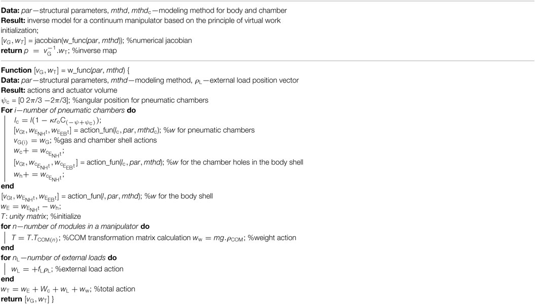
Algorithm 1. The pseudo code for a Matlab program to derive the inverse static relation for a continuum manipulator using the principle of virtual energy and constant curvature assumptions.
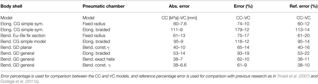
Table 2. Performance comparison between different models for random pressurization of one STIFF-FLOP module under body weight loads vs. 43 experimental data points, and under an extensive external load vs. 33 experimental data points.
4.2. Extension to Variable Curvature Model
The solutions provided in the previous sections improve the modeling of the cross-section deformation with constant curvature assumption. This solution can be extended to the variable curvature backbone model, where the backbone consists of a series of infinitesimal constant curvature curves (Trivedi et al., 2007; Burgner-Kahrs et al., 2015; Neumann and Burgner-Kahrs, 2016). The variable curvature assumptions improve the accuracy of the backbone deformation modeling, and the presented methods in this research can improve the associated cross-section deformation models.
4.3. Variable Curvature Kinematics
Variable curvature kinematics presents the relation between local curvilinear frames with normal (d1), tangential (d2), and binormal (d3 = d2 × d1) unit vectors along the backbone of a continuum media (Figure 2D). The backbone is considered to be consisting of a series of infinitesimal length constant curvature curves along the main axis. The translational (ξ) and rotational (ζ) strain rates w.r.t. the unit length along the manipulator backbone curve (s) in the local curvilinear frames are found from a dynamic map based on Cosserat rod model or Euler–Bernoulli rod model as a special case with infinite shear modulus.
A set of rotation matrices (R(s)) gives the relation between the local transnational strains and the deformation rates of the spatial geometry of the manipulator as
where ξ is the strain rates in the local curvilinear frame, which the rotation matrix R(s) rotates to be expressed in the reference Cartesian frame. This rotated representation is equal to the variation of the position vector from one local frame to the next one (ρ(s),s) along the backbone unit length (s).
R(S) is found from the local rotational strain rates (ζ). The rotation matrix variation along the backbone unit length (R(s),s) can be found as
where []× is an operator to create a skew symmetric matrix. Equation (49) presents the kinematic relation between the rotation matrix variation (R(s),s) and the rotational strain rates expressed in the local frame (ζ) along the manipulator backbone curve (Neumann and Burgner-Kahrs, 2016). Integrating equation (48) for ρ(s) and equation (49) for R(s) presents the variable curvature kinematics. The next step is finding the local strain rates based on the system loads from the dynamic map.
4.4. Beam Theory (Cosserat) Model
A Cosserat rod model can be used to derive the dynamic map. Cosserat rod models derive the equilibrium between the forces on each infinitesimal element of a continuum media based on Newtonian approach and a free force body diagram of each element (Trivedi et al., 2007). Then, the inter-element load effects are replaced by the resultant stresses. Hooke’s law is usually used to relate these stresses to the strain rates. Rearranging the derivation to find the strain rates based on the loads, results in a boundary value problem with partial differential equations (PDE) of order two that needs to be integrated over volume and time. This derivation becomes simpler for the static planar case (Trivedi et al., 2007).
The general derivation of the Cosserat rode method can be found in the literature (Trivedi et al., 2007; Tunay, 2013; Neumann and Burgner-Kahrs, 2016) and not presented here. The Euler–Bernoulli beam model is an alternative approach to derive the same final relation in the form of a PDE of order one, where the resultant stresses are found from the total load exerted on each cross section from one side of the beam. The loads are usually calculated based on the loads from the free end side of the beam. The Cosserat rod model reduces to the Euler–Bernoulli beam model in the case of infinite shear modulus. The Euler–Bernoulli method results in the following static map for a planar continuum manipulator in the static case,
where fb(s) = ba(l − s). g is the body weight force, is the pneumatic pressure force, g = [0, g, 0]T is the gravity acceleration vector (upward in the simulations), is the external load moment, is the body weight moment, is the pneumatic pressure moment exerting at the manipulator tip, and is the deformed placement radius for the pneumatic chambers, all in deformed state. The deformed values in each element along the backbone curve are found by substituting λt = ξ2 + 1 and in equations from section 3.4 and 3.5. Substituting equation (50) in equations (48) and (49) and integrating the result give the full model for the manipulator. We use the backbone area and second moment of inertia for the deformed body to account for the cross-section deformation.
5. Simulation and Comparison
We investigate the accuracy of the simulations from different models in predicting the experimental results and the sensitivity of each model to structural and kinematic parameters. The comparison between the models helps to understand how the modeling accuracy improves by increasing the mathematical derivation complexity and to find the proper model to observe certain behaviors, incorporate effects of important structural parameters, and achieve a desired modeling accuracy. Modeling absolute error is defined as the positive value of the difference between the output vector (pressure (p) for the inverse model (section 5.4) and tip position vector (ρtip) for the forward model (section 5.5)) from the model simulation and the experiments. Error percentage is found by dividing the absolute error by the vector value from the experiments as the reference value and used as a means to compare constant curvature and variable curvature modeling results despite their differences. To make comparison with similar research easier, a reference error percentage is defined where the absolute error is divided by a structural parameter as the reference value (E for the inverse model (section 5.4) and module length (l + 2lfs) for the forward model (section 5.5) (Trivedi et al., 2007)). We use error percentage to compare different models in this research; however, the reference error percentage should be used for comparison to results from other similar research.
5.1. Helix Lead Angle Models
Simulation results for γ(ψ) in terms of different values of γ, κ, and show considerable changes in the local lead angle, w.r.t. the initial lead angle (γ) and the uniform changes in the lead angle after pure elongation (γe), even for γ ≈ π/2 (Figure 3A). The variations from the base lead angle (γ) increase significantly as the γ itself decreases and as increases. However, it decreases slightly when κ increases and there is no notable variation w.r.t. θ = κlc. γ produces the dominant effect and enhances the effect of other parameters as it decreases. Results from the exact model [equation (22)] and the simplified model [equation (25)] are almost identical while the simplified model predicts slightly larger variations in the local lead angle; Hence, we continue with the simplified model. The small lead angle assumption (γ(ψ) ≈ π/2) in all the derivations causes a larger error w.r.t. the exact model and predicts more local change in γ(ψ). With local changes in γ(ψ), the errors of the three models remain small for γe > 80°, and they have identical results for γ = π/2 as expected.
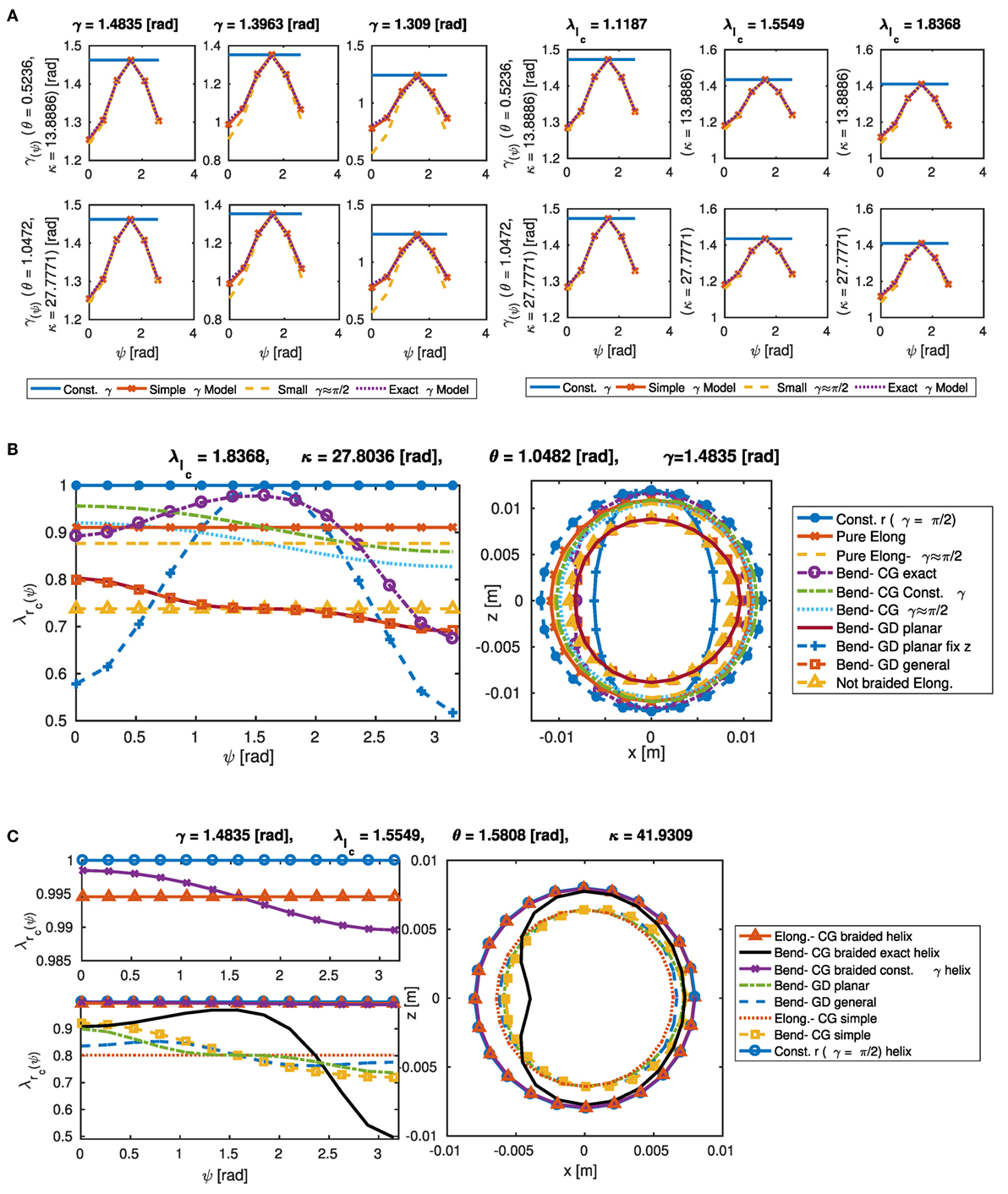
Figure 3. The change in the local lead angle (γ(ψ)) of a pneumatic chamber’s helical thread in terms of different values of γ, κ, and where [(A), left] and γ = 1.4835 rad [(A), right]. The model with dense thread (small γ ≈ π/2) tends to predict more change in γ(ψ) (A). The change in the outer radius stretch ratio [(B), left] and shell cross-section deformation [(B), right] of a pneumatic chamber for rc2 = 12 mm, , κ = 27.8036 rad, θ = 1.0482 rad, and γ = 1.4835 rad (B). The change in the inner radius stretch ratio [(C), left] and cross-section deformation [(C), right] of a pneumatic chamber where rc1 = 8 mm, = 1.5549, κ = 41.6922 rad, θ = 1.0482 rad, and γ = 1.4835 rad (C). Note how the cross-section shape changes based on different model assumptions.
5.2. Comparison of Deformation Models for a Braided Actuator
Simulation results for different derived models of and cross-section shapes of a STIFF-FLOP pneumatic chamber in terms of γ, κ, θ, and are presented in Figures 4A,B. The exact helix model as in equation (28) predicts the largest variation from the circular shape such that the cross-section radius will shrink more in both the inner (concave) and outer (convex) sides of the curve in the bending plane and w.r.t. the tangential plane. The deformation of the radius on the inner side is smaller than the deformation of the outer side, and this difference increases as either θ or κ increases, in addition the deformation magnifies when γ decreases and/or increases. However, it decreases when κ is increased for a constant θ and increases when κ is increased for a constant . The most significant parameter on the cross-section asymmetric deformation is the bending angle (θ), and its effect is enhanced by the braid helix lead angle (γ) decreasing as well as the axial stretch ratio increasing. The observed effects intensify for bigger radii. The small lead angle case (γ ≈ π/2) for the exact helix model predicts a larger uniform decrease in the shell radius, which we found unsuitable for modeling purposes and is not presented in the graphs.
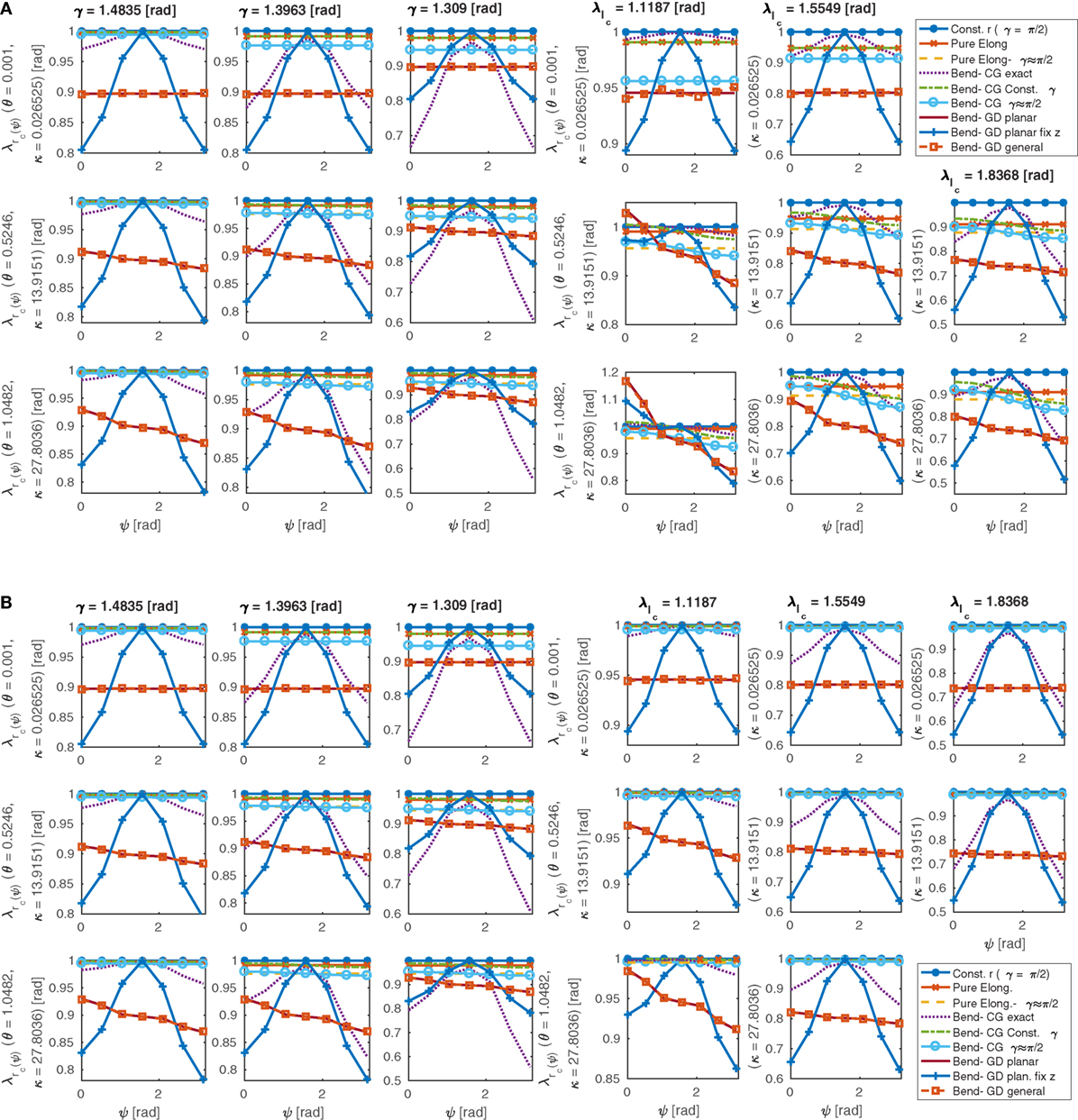
Figure 4. The change in the outer radius stretch ratio (left) and shell cross-section deformation (right) of a pneumatic chamber in terms of different values of γ, , κ, and where γ = 1.4835 rad (left) and (right). For a module with large radius (rc2 = 12 mm) for better presentation of the model assumption effects on the cross-section deformation (A), and the STIFF-FLOP pneumatic chamber (rc2 = 3 mm) (B). Different scales for the y-axis are used for better visibility. Note how the different assumptions change the cross-section shape by changing the profile; and the different predicted profile for a module in nearly pure bending with a large bending radius ( and θ = 1.0482 rad) in panel (B) compared to a module with bigger radius in panel (A).
Despite the exact helix model, the constant lead angle assumption [equation (29)] predicts an almost uniform shift in the cross section toward the bending axis. The structural parameters have almost the same effects on the deformation predicted by this model as discussed for the exact helix model; however, their effects are not significant. The constant lead angle model in the general case corrects the pure elongation general case, and the small lead angle case (γ ≈ π/2) corrects the small angle case for the pure elongation. The small lead angle models predict a slightly smaller radius compared to the general cases; however, they are not significantly different from the fixed radius models (γ = π/2) and from each other in terms of the prediction of the shell radius deformation. Assuming γ ≈ π/2 results in slightly larger predictions for radius and thread local lead angle. The results are in good agreement with the exact models for γe > 80°; however, the simplification does not reduce the complexity of derivations significantly.
The exact helix model assumes the braid helix deforms due to pure torsion of the thread cross section, similar to a stiff spring, without any bending. This assumption for the constant lead angle model is not valid, and this model’s prediction is similar to the result from the pure elongation of a helix [equation (12)]. We suggest using the exact helix model for the chambers with stiff braids, and using the constant lead angle model for more deformable braids, i.e., sewing threads, where the deformation of the chamber shell is more dominant. The deformation of the cross section and the difference between the models become noticeable when γ > 1.309 rad or . However, to understand the significance of this difference on the static model of a chamber, we investigate the action predicted by any of the models later.
Note the different predicted profile for a module in nearly pure bending with a big radius ( and θ = 1. 0482 [rad]) in Figure 4B compared to a module with smaller radius in Figure 4C.
Different predicted deformations based on different models for the outer and the inner radius of a braided pneumatic chamber with inner and outer diameter of, respectively, 12 and 18 mm and γ = 1.48354 rad are presented in Figures 3B,C. Results for a body shell without braids are presented for comparison purposes too. The deformation predicted by all the braided models other than the bending model with the exact helix γ assumption is almost identical to the prediction of the constant radius model for this γ. A closer look shows a small decrease in the radius in case of pure elongation of a helix. The radius changes somewhat for the bending model with the constant γ assumption and slightly expands inward. The bending model with the exact γ assumption shows a helix that does not allow lateral deformation other than the uniform reduction due to the elongation of the axis. It causes a change in the twist angle at the back side of the bent where two consecutive rounds of the helix have different local lead angles and create a heart shape. While a tube inside a helical spring behaves similar to the exact γ assumption model, the thread tends to follow the deformation of the body shell for the softer braids and to maintain γ; therefore, it behaves similarly to the constant γ assumption model. It is clear that the helix tends to maintain the radius, and the braided chamber does not shrink in radius as does the simple cylinder without braids.
Cross-section deformation of a pneumatic chamber for the STIFF-FLOP module is presented in Figure 5A for different bending angles. It is clear that the change in the shape of the cross section in the Figure 5A is less obvious than in Figure 4C with bigger inner and outer radius. The inner cross-section shape deformation is more obvious. The chamber tends to remain circular in all cases except for the bending with exact γ model, where the tube shell tends to bend inward and become more like a bean. This bean shape is consistent with our observation for the STIFF-FLOP pneumatic chamber, despite the thread that is used in making the chamber bends easily.
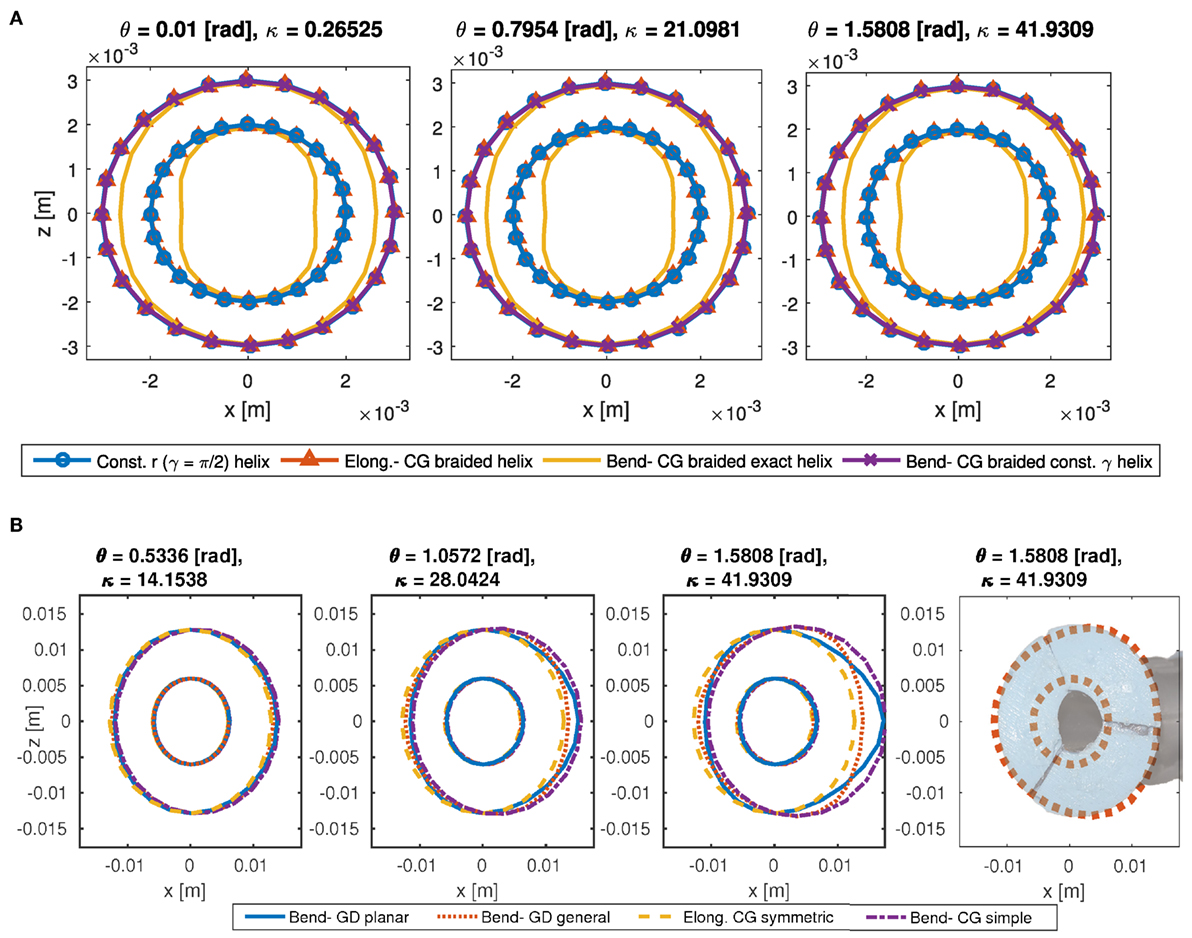
Figure 5. The cross-section deformation model for a STIFF-FLOP pneumatic chamber where and γ = 1.4835 rad (A). The cross-section model for deformation of STIFF-FLOP body shell where and γ = 1.4835 rad [(B), left] and comparison with experiment [(B), right]. The area changes to an egg shape and shifts toward the inner of the bent. The GD- planar model predicts less material shift compared to the general model. The GD- general method provides a better prediction of the cross-section deformation (B).
The predicted deformation by different models for a STIFF-FLOP body shell is presented in Figure 5B, where deformation due to a pure symmetric elongation is presented too for comparison. The simple bending model based on Cauchy–Green stretch ratios (CG- simple bending model) and the planar bending model from the geometry deformation model (GD- planar model) predict more shift in the cross section toward the bending side. The CG- simple bending model predicts an almost uniform shift in the cross section toward the bending axis. The planar bending model predicts an egg shape cross section with the sharp side toward the bend center. The general geometry deformation model (GD- general bending model) predicts a smaller shift toward the bending axis, and a small lateral shrink at the back of the bending side and a small lateral expansion at the inward. Based on the shift and the overall shape, we conclude that the GD- general bending model predicts the most realistic deformation. A comparison between the GD- general bending model and the actual cross-section deformation of the body shell is presented in Figure 5B too.
5.3. Comparison of Pressure and Action Models for a Braided Actuator
The pressure required for one pneumatic chamber to reach a certain λt is found by exploiting the principle of virtual energy for one pneumatic chamber. The result from different braided chamber models is compared against experiments with a STIFF-FLOP chamber in Figure 6. The variation w.r.t. the bent curvature is neglected for the bending models; however, as the standalone actuator chamber bends when it pressurized shown in Figure 1G, we simulate the results for different in θ = 1.482 rad. It is observed that the constant γ model and the exact helix model give the best prediction based on the actual measured values. The results are very sensitive to the verified parameters. For example, in Figure 6, by choosing a slightly different value for E and γ the bending with constant helix model can predict the pressure values precisely while this model is less sensitive to a change in E compared to the other models. Therefore, we choose the model that predicts the behavior trends in the experimental data and then we identify the unknown structural parameters to fit the model to the experimental readings. The trend in the experimental values and small sensitivity to the γ value show that the constant γ model has the best prediction for this chamber. This result was predictable due to easily deformable threads having been used in making this chamber. There is no significant change in the model predictions for different values of θ and γ, other than the pressure value predicted by the GD- general bending model, which is shown to be very sensitive to the value of γ, where the pressure increases significantly as γ reduces. This very sensitive behavior needs more experiments for verification when using chambers with variable thread angles.
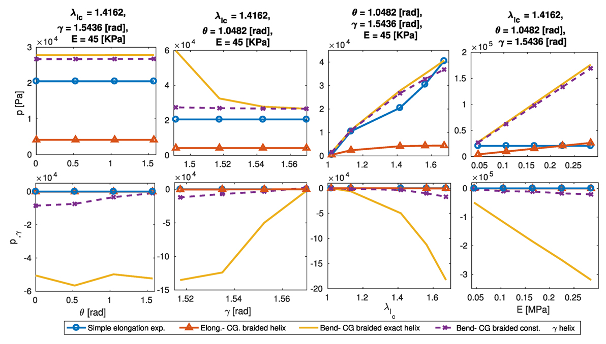
Figure 6. Required gas pressure for a certain deformation of a STIFF-FLOP pneumatic chamber, experimental data vs. model simulations (top), sensitivity of the predicted required pressure to the structural parameter γ by plotting p,γ for different values of θ, γ, , and E (down). The CG- exact helix model shows better prediction in terms of mean error and profile shape, however, predicts high non-linear sensitivity.
The elastic deformation from the Neo-Hookean (NH) and Euler–Bernoulli (EB) methods, and gas pressure actions w.r.t. different values of θ, , and γ predicted by different models are presented in Figure 7A for a STIFF-FLOP pneumatic chamber. The gas pressure action does not change for different values of θ and γ, except for the GD- exact helix model that demonstrates a significant increase as γ increases. The most important parameter is , which causes a significant increase in the actions. For the CG- bending model with fixed radius (the case of dense braids, γ ≈ π/2), a decrease in the Neo-Hookean elastic deformation action is observed, which suggests this assumption cannot be used with the Neo-Hookean method. The graphs show some models predict the actions up to 3 times more compared to other models, which show the importance of a proper choice of modeling method. The predictions from GD- exact γ and the planar deformation assumptions are quite similar. The Euler–Bernoulli method predicts significantly higher values than the Neo-Hookean method. For the models with fixed radius, dense tread, or neglecting the pneumatic chamber shells, larger values for the actions are calculated. In general, any simplifying assumption causes an overestimation of the actions. While the action values are representations of the energies stored in the system, the actions variation w.r.t. system states determines the final static map for the system.
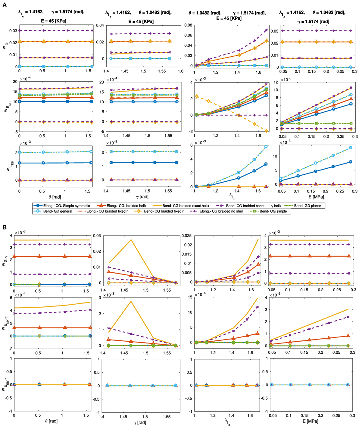
Figure 7. The gas pressure action (wG), body deformation energy using Neo-Hookean and Hooke’s methods vs. change in the helix and curvature parameters (A). Sensitivity analysis of the action values w.r.t. γ by plotting w,γ for different values of θ, γ, , and E (B). High complexity models, i.e., GD- exact helix models, predict high non-linear sensitivity, and the simplified models, i.e., CG- braided fix radius, predict higher and, in some cases, incorrect sensitivity values and profile.
5.4. Constant Curvature Model
We attempted to identify the unknown values such as γ, E, and sensor frame initial register by fitting the model simulations to the actual experiment information for eight data points and subsequently verifying the result against 43 data points. All the remaining parameters were measured manually. It was observed that a combination of the geometry deformation method with general assumptions for the body shell and the bending model with the exact helix lead angle assumption provides the best modeling accuracy. This might have been predicted based on the previous observations about the body shell and pneumatic chamber. This method increases the accuracy of the model by up to 13% mean error compared to a simple CG- symmetric elongating body shell with fixed radius chambers and 14% compared to Euler–Bernoulli bending model with fixed cross section. A better accuracy is possible if a CG- pure elongating braided helix model is used instead of the helix fixed radius model. Using the simplified models such as the CG- simple bending or fixed radius assumption increases the modeling error by up to 57% compared to the best possible solution. The general deformation derivation [equation (45)] provides a better solution for the problem of flexure compared to the planar deformation method [equation (40)] based on Rivlin’s method (Rivlin, 1949). The Euler–Bernoulli model with fixed radius assumption for the actuator chambers results in better accuracy compared to the Neo-Hookean models in this case; however, the correct choice of the combination of the methods is still important, i.e., in incorporating the structural parameters’ effect. It is clear that more exact modeling of the deformation of the cross section increases the modeling accuracy significantly, even if this prediction has been made based on a simple symmetric pure elongation model. However, a carefully chosen combination of the models based on the nature of the module is important to achieve the best result. The overall mean error of the model is high (61% mean error percentage and 38% mean reference error percentage) because of the inaccuracy in constant curvature assumption, especially for near straight configurations, as observed in similar previous research (Trivedi et al., 2007; Godage et al., 2011a). A comparison between the best and the worst model prediction is presented in Figure 8 showing the importance of considering the cross-section deformation.
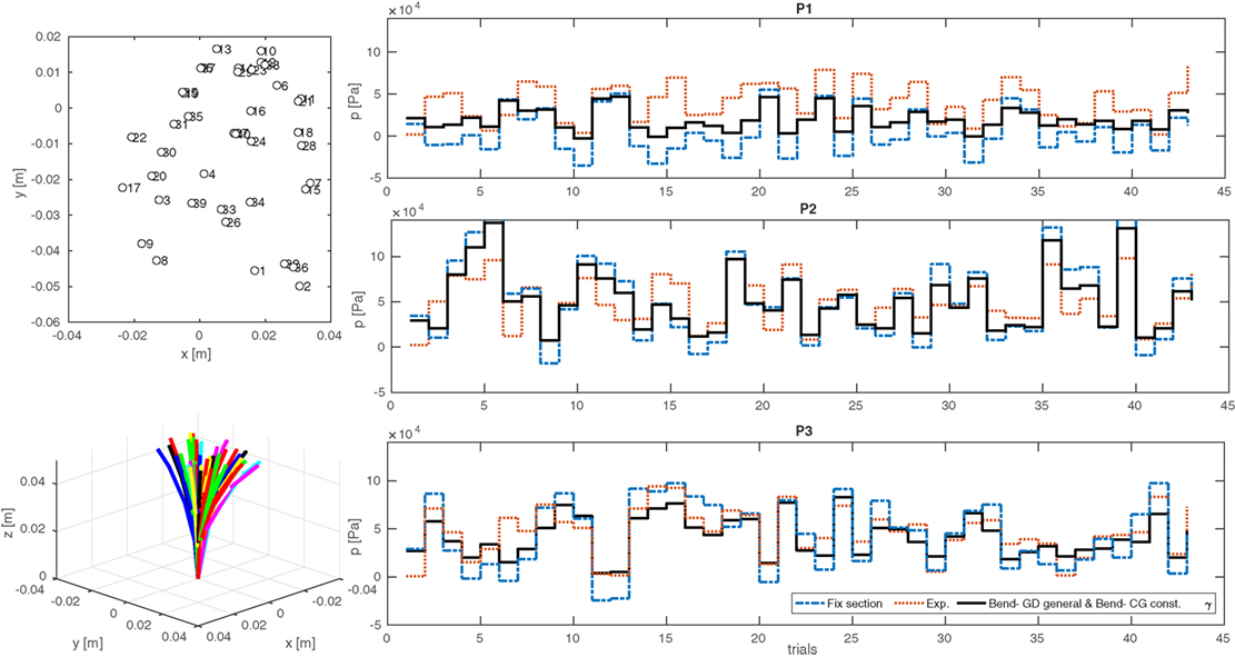
Figure 8. The simulation vs. experimental results from 43 data points for inverse static relation between the input pressures and the tip position for a STIFF-FLOP pneumatic chamber, using principle of virtual work. A combination of the GD- general method and the constant γ model shows 13% lower mean error percentage and 23% lower mean reference error percentage compared to the Euler–Bernoulli rod model without any cross-section deformation.
5.5. Variable Curvature Model
Equation (50) needs to be solved for the deformed geometry in the equilibrium state. We start with a guess for the deformed geometry, i.e., straight configuration, and solve for the manipulator geometry where the result should be identical to the first guess. This leads to a system of non-linear equations that can be solved with numerical methods such as Powell dogleg (Powell, 1970) used in Matlab “fsolve” function. Starting from the straight undeformed state shows good convergence, and the algorithm usually needs two trials to find the equilibrium configuration for a single-curve formation and three trials for a double-curve formation (Figure 1C).
We investigate the Cosserat rod model accuracy to simulate the planar deformation of one STIFF-FLOP module with extensive external loading shown in Figure 1C. A Matlab program algorithm is presented in Algorithm 2. The overall accuracy of the Cosserat rod model is about 52–100% better than the constant curvature model for any combination of the models. Approximately the same trend in the accuracy of the models is observed here compared to the constant curvature model. The combination of the bending GD general deformation or planar assumption and the exact or constant γ helix model results in a small 9–10% error. The error for the combination of the CG symmetric elongation model and the helix pure elongation results in 12% error, which is slightly less than the accuracy of the models based on the general deformation method. A comparison between the combination of the GD- general bending models and the constant helix angle (γ) model with the model without any change in the cross section is presented in Figure 9 showing 7% increase in the model accuracy by taking into account the cross-section deformation based on mean reference error. The model reference error percentage is 10% for the case with extensive external load and less than 5% in the case that only the body weight is present, which is similar to the results reported in Trivedi et al. (2007) and Godage et al. (2011b). Model complexity provides a more accurate solution but increases the time that the numerical non-linear solver needs to find a feasible solution. This is due to increased computation time and highly non-linear behavior of the model complexity.
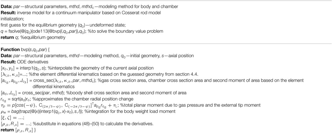
Algorithm 2. A pseudo code for a Matlab program to solve the forward static relation for a continuum manipulator using the Cosserat rod method.
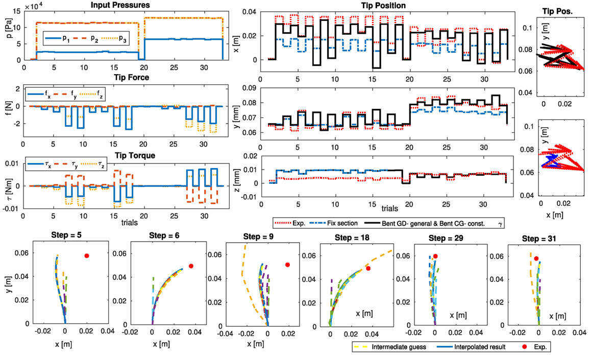
Figure 9. The simulation vs. experimental result from 33 data points for planar deformation of one STIFF-FLOP module under extensive external loads (Figure 1C). A combination of GD- general method and exact helix model shows 7% lower mean error percentage and 10% lower mean reference error percentage compared to the Euler–Bernoulli rod model with no cross-section deformation. The VC model shows 52% lower mean reference error percentage than the CC model (Figure 8). The iteration to solve the BVP problem for some of the simulation steps is presented (bottom).
5.6. Sensitivity Analysis
An analytical model is beneficial for design by providing an efficient means for sensitivity analysis and optimization of the system performance w.r.t. the structural parameters. Here, we investigate the sensitivity of the predicted deformation profiles, the input pressure, and deformation energy actions to changes in γ and E, as the two important structural parameters in the design of stiffness controllable braided actuators, by deriving the gradient of these values w.r.t. γ and E. The resulting non-linear relations are plotted for different values of γ, κ, , and E, showing the sensitivity of the results in any geometrical action point and for any combination of the other structural parameters.
For γ(ψ) as in Figure 10, the exact γ and the dense thread (γ = π/2) models sensitivity to a change in γ decreases as γ decrease and increases. Unlike γ(ψ), the sensitivity of to the change of γ increases by the increase in and κ and decrease in γ showing more sensitivity in pure elongation cases for a module with a less dense braid. The model with simplifying assumption of γ ≈ π/2 overestimates the predicted values as observed in the previous sections.
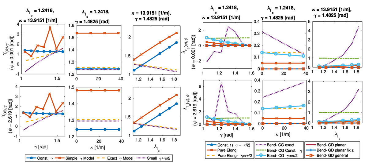
Figure 10. Sensitivity of predicted values of γ(ψ) (, left) and (, right) from different models to change in γ for different values of γ, κ, and . The CG- exact model that uses simple γ model shows highly non-linear sensitivity for different values of γ, which is not similar to that of the exact γ model. The model with dense thread assumption (γ ≈ π/2) shows higher sensitivity.
The sensitivity of the deformation action, gas pressure action (Figure 7B), and required pressure for a braided actuator to reach a certain elongation (Figure 6) to changes in γ increases for a more stiff actuator (increase in E) with a less dense thread (decrease in γ) and in a pure elongation case (decrease in θ and increase in ). The sensitivity of p decreases for a high bending angle cases while slightly increases for the deformation actions. p and w are linear functions of E, and their sensitivity to changes in the module stiffness is similar to the graphs for p and w where the values are divided by the value of E in our simulation (10 kPa).
The CG- exact model that uses a simplifying assumption for γ, as in equation (23), results in a highly non-linear gradient w.r.t. γ, which is not similar to that of the exact γ model in Figure 10. This is predictable as the simplifying assumption only holds for small values of γ and predicts greater changes in the sensitivity, similar to the other models with similar simplifying assumption.
6. Discussion
First, cross-section deformation of a STIFF-FLOP chamber in terms of structural and bending parameters using different methods is presented in Figure 4A,B. The exact helix model predicts a bean like cross section with small lateral deformations, and the constant γ assumption predicts a uniform shift in the cross section toward the bending axis. A larger uniform decrease in the cross section is predicted for the small lead angle assumption (γ ≈ π/2). The most effective parameter on the asymmetric deformation of the cross section is the decrease in the bending angle (θ) and the braid helix lead angle (γ), where the increase in the axial stretch ratio and initial radius enhances these effects. The structural parameters have fewer effects on the models with the constant γ and dense braid assumptions. The dense braid assumption predicts a slightly smaller deformed radius compared to the model for simple elongation of a helix. These models are valid for γ > 80°[deg], however, are not recommended as they do not reduce the derivation complexity significantly.
The braided chamber cross-section deformations predicted by any of the models are presented in Figure 3B,C. The elongation of a helix results in a small uniform reduction of the radius and the constant γ assumptions added a small shift toward the bending angle too. There is no lateral deformation in the exact helix model in pure bending resulting in a heart shape deformed cross section due to a notable different twist angle at the start and end of each thread rounds. In general, the braided chamber radius deformation is smaller than the cases without braids. The experimental results for a STIFF-FLOP module are presented in Figures 5A,B.
The exact helix model assumes pure torsion of the thread cross section, which is valid for a stiff thread similar to metallic springs. The bendable thread, i.e., sewing threads, being use for many micro soft manipulators tend to follow the deformation of the chamber body; hence, the constant γ assumption should work better with them.
Next, we investigated the action predicted by the models. A considerable shift in the cross section toward the bending axis is observed for the CG- simple bending model (uniform shift), the GD- planar models (egg shape), and the GD- general bending model (trapezoidal shape). The most realistic shift and overall deformation compared to the experiment results are predicted by GD- general bending model (Figure 5B). As predicted, the constant γ model gives the best prediction of pressure vs. λc for one pneumatic chamber (Figure 6). Despite that the results are very sensitive to the identified value for E, we choose the model that shows a better agreement with the behavior trends observed from the experiments. The results for the GD- general bending model are shown to be very sensitive to the value of γ as can be predicted for a spring.
The elastic deformation and gas pressure actions are shown to be very sensitive to the backbone elongation compared to the bending angle (θ), showing the dominance of the pure elongation effect over the bending for static modeling (Figure 7A). Simplifying assumptions (fixed radius, dense tread, neglecting the chamber shells, and Euler–Bernoulli linear stress–strain relation) results in the overestimation of the actions values (up to three times).
A comparison of using different combination of the models for the pneumatic chambers and the body shell with the experiment results shows that a combination of GD- general bending model for the body shell and the bending helix with constant γ provides the best modeling accuracy as we anticipated from the previous observations (Table 2; Figure 8). It is clear that the modeling accuracy increases by using more realistic models for the deformation of the cross section (13% less mean error percentage). The results from the simple symmetric elongation and the fixed radius chamber models can be more accurate if, instead of using the real measured values, we identify the structural parameters by fitting the simulation results to the experiment values.
Despite all the improvements from implementing the cross-section deformation models, the overall simulation accuracy is relatively low (up to 62% mean error and 38% mean reference error). We showed 52–100% fewer simulation errors by using the Cosserat rod model in the case of high external loading where the combination of the GD- general deformation or planar assumption and the exact or constant γ helix model results in a small 8% error, and the combination of the CG symmetric elongation model and the helix pure elongation shows 10% error (Figures 2C and 9). The model error is less than 5% in the case that only the body weight is present. The Hooke’s law for linear stress–strain relation used in equation (50) can be substituted with a more realistic model, i.e., Neo-Hookean, Mooney-Rivlin, or Gent relations based on the deformation rate matrix invariants of a highly deformable material, in the future to further improve the modeling accuracy (Gent, 2012).
We observed that considering the cross-section deformation increases the simulation accuracy up to 10% for the Cosserat rod model and 13% for the constant curvature model compared to the constant cross-section models. The combination of the geometry deformation method and bending helix model has the best result with up to 2% more accurate results compared to the other models for the cross-section deformation. The reference error percentage is used to compare the modeling accuracy with similar research where we showed 38% error for the inverse relation in the model with constant curvature assumption and body loads, 5% error for the forward relation in the model with variable curvature assumption and body loads, and 10% error for the case with extensive external loads. Our results comply with the 5% error observed by the modeling errors reported in Trivedi et al. (2007) and Godage et al. (2011a) for the cases without extensive external loads, while our models incorporate the information about the cross-section deformation too. Our results suggest the importance of the cross-section deformation in the modeling accuracy, which confirms its evident importance for minimal invasive manipulation with small workspaces and for the manipulators with regional controllable stiffness in their cross section.
The sensitivity of local deformation rate of the cross-section radius predicted pressure for a certain elongation (p), and deformation and pressure actions (w) to changes in the braid initial lead angle (γ) increases as the module elongates and for a less dense braiding, while the sensitivity of the local lead angle (γ(ψ)) w.r.t. γ decreases in the same conditions. γ(ψ) is not sensitive to the actuator curvature, p becomes less sensitive, and the sensitivity of w slightly increases as the actuator bends. The sensitivity of to γ for different bending angles is related to the polar position of the points with decreasing sensitivity for the points on the inside of the bending module and increasing sensitivity for the ones on the outside. The model is linearly sensitive to changes in the module stiffness (E) as all the relations are linear functions of this parameter. Models with more complexity or simplifying assumptions about the thread lead angle predict higher values and non-linearity for the model sensitivity. This shows the importance of an accurate derivation for the models with increased complexity and avoiding simplifying assumption about the thread lead angle to achieve robust results. The fact that the resulting predictions for the system behavior and model sensitivity to parameters can be different for different models show the importance of proper choice of model assumptions and complexity level.
We believe our simple analytical model for the cross-section deformation can play the same role as the constant curvature assumptions in providing a simple estimation of the backbone kinematics, for the manipulators with a variable stiffness cross section. A suggestion for a future research is to improve the model by considering the material hysteresis and damping effects as well as incorporating adaptive terms in the model to take into account for the changes in the material properties and repeatability of experimental results as presented to some extent in Shapiro et al. (2011). For the minimal invasive surgery applications with limited workspace, as the main aim of our future research, we plan to implement the tactile information from the continuum manipulator in the modeling and verification steps to investigate safe skin guiding of a robot movements against soft organs where having information about the robot cross-section deformation in contact with the tissue is beneficial.
7. Conclusion
In this paper, supported by experimental validation using the real characteristics of a STIFF-FLOP module base, we present a new geometry deformation approach for comprehensive analytical modeling of compound continuum manipulators with braided extensile actuators under high external loading. For the first time, elongation–bending deformation of a braided extensile pneumatic chamber is modeled for both the stiff (exact helix model) and bendable (constant γ assumption) threads, and the effects of simplifying assumptions on the results are investigated. Subsequently, two novel yet simple analytical solutions are derived for the prediction of the cross-section deformation in constant curvature elongation–bending of a continuum media. The effects of different structural and curvature parameters on the predictions of the models are investigated. We show that the energy action values are more sensitive to the elongation rate of the backbone than the curvature of the bending curve, and the model benefits from an accurate backbone model more than the accuracy of prediction of the cross-section deformation. We also show that consideration of the cross-section deformation increases the modeling accuracy significantly for constant (up to 13%) and variable curvature (up to 7%) kinematics using the principle of virtual work and Cosserat rod theory. The results are verified by comparison to experimental results. We show the combination of the general bending model based on the geometry deformation approach and the constant γ model for the helix gives the best set of simulation results, which is in agreement with our predictions, suggesting the importance of considering the cross-section deformation in the modeling accuracy. The sensitivity of the models’ prediction to changes in γ and E, as the two important structural parameters in the design of stiffness controllable continuum modules with braided actuators, is investigated analytically, showing that our models can be used for comprehensive exact modeling and design optimization of manipulators with compound structures especially for the minimal invasive applications where the task space is limited and for the manipulators with regional tunable stiffness cross sections. Our results provide a comprehensive insight in choosing proper modeling assumptions and complexity to observe certain behaviors and achieve the desired accuracy.
Author Contributions
SS is the main author who developed the main idea and carried on the experiments, derivations, and simulations. He prepared the draft as the main author. SN contributed in development of the main idea and derivations with helpful comments and good scientific insight where the topic felt outside of the main author expertise especially in continuum mechanics perspective. AS designed one of the experimental setups and contributed in the verification of the method. YN fabricated the test setups and measurement equipment. AG fabricated different designs of the STIFF-FLOP continuum manipulator and extensile pneumatic actuators used for the justification of the design and properties of the manipulator. IW helped in development of the idea, planning the structure of the research, and final editing of the draft. KA supervised the progress of the research and provided helpful comments on its progress and preparation of the draft. TN supervised the research, guided its progress, provided helpful comments on all of the aspects of this research and in the preparation of the final draft. He is my main PhD supervisor.
Conflict of Interest Statement
The authors declare that the research was conducted in the absence of any commercial or financial relationships that could be construed as a potential conflict of interest.
The reviewer AC and handling Editor declared their shared affiliation, and the handling Editor states that the process nevertheless met the standards of a fair and objective review.
Funding
This work was partly supported by UK Engineering and Physical Sciences Research Council (EPSRC) MOTION grant (grant number EP/N03211X/2), European Union H2020 project FourByThree with code 637095 and EU FP7 framework STIFF-FLOP grant under agreement 287728.
References
Alambeigi, F., Seifabadi, R., and Armand, M. (2016). “A continuum manipulator with phase changing alloy,” in IEEE International Conference on Robotics and Automation (ICRA) (Stockholm: IEEE), 758–764.
Burgner-Kahrs, J., Rucker, D. C., and Choset, H. (2015). Continuum robots for medical applications: a survey. IEEE Trans. Robot. 31, 1261–1280. doi: 10.1109/TRO.2015.2489500
Chen, G., Pham, M. T., and Redarce, T. (2009). Sensor-based guidance control of a continuum robot for a semi-autonomous colonoscopy. Rob. Auton. Syst. 57, 712–722. doi:10.1016/j.robot.2008.11.001
Cheng, N. G., Gopinath, A., Wang, L., Iagnemma, K., and Hosoi, A. E. (2014). Thermally tunable, self-healing composites for soft robotic applications. Macromol. Mater. Eng. 299, 1279–1284. doi:10.1002/mame.201400017
Cianchetti, M., and Menciassi, A. (2017). “Soft robots in surgery,” in Soft Robotics: Trends, Applications and Challenges, Vol. 9 of Biosystems & Biorobotics, 1st Edn (Springer International Publishing), 75–85.
Cianchetti, M., Ranzani, T., Gerboni, G., De Falco, I., Laschi, C., and Menciassi, A. (2013). “STIFF-FLOP surgical manipulator: mechanical design and experimental characterization of the single module,” in IEEE International Conference on Intelligent Robots and Systems (IROS) (Tokyo: IEEE), 3576–3581.
Cianchetti, M., Ranzani, T., Gerboni, G., Nanayakkara, T., Althoefer, K., Dasgupta, P., et al. (2014). Soft robotics technologies to address shortcomings in today’s minimally invasive surgery: the STIFF-FLOP approach. Soft Robot. 1, 122–131. doi:10.1089/soro.2014.0001
Cohen, C., Hiott, B., Kapadia, A. D., and Walker, I. D. (2016). “Robot tongues in space: continuum surfaces for robotic grasping and manipulation,” in Micro- and Nanotechnology Sensors, Systems and Applications VIII (Baltimore, MD: SPIE), Vol. 9836, 98362B.
Duriez, C. (2013). “Control of elastic soft robots based on real-time finite element method,” in 2013 IEEE International Conference on Robotics and Automation (ICRA) (Karlsruhe, Germany: IEEE), 3982–3987.
Duriez, C., and Bieze, T. (2017). “Soft robot modeling, simulation and control in real-time,” in Soft Robotics: Trends, Applications and Challenges, Vol. 12 of Biosystems & Biorobotics, 1st Edn (Springer), 103–109.
Follmer, S., Leithinger, D., Olwal, A., Cheng, N., and Ishii, H. (2012). “Jamming user interfaces: programmable particle stiffness and sensing for malleable and shape-changing devices,” in Proceedings of the 25th Annual ACM Symposium on User Interface Software and Technology (Cambridge, MA: ACM), 519–528.
Gent, A. N. (2012). Engineering with Rubber: How to Design Rubber Components. Munich, Germany: Hanser Publishers.
Giri, N., and Walker, I. D. (2011). “Three module lumped element model of a continuum arm section,” in IEEE International Conference on Intelligent Robots and Systems (IROS) (San Francisco, CA: IEEE), 4060–4065.
Godage, I. S., Branson, D. T., Guglielmino, E., Medrano-Cerda, G. A., and Caldwell, D. G. (2011a). “Shape function-based kinematics and dynamics for variable length continuum robotic arms,” in 2011 IEEE International Conference on Robotics and Automation (ICRA) (Shanghai, China: IEEE), 452–457.
Godage, I. S., Guglielmino, E., Branson, D. T., Medrano-Cerda, G. A., and Caldwell, D. G. (2011b). “Novel modal approach for kinematics of multisection continuum arms,” in IEEE International Conference on Intelligent Robots and Systems (IROS) (San Francisco, CA: IEEE), 1093–1098.
Godage, I. S., Medrano-Cerda, G. A., Branson, D. T., Guglielmino, E., and Caldwell, D. G. (2016). Dynamics for variable length multisection continuum arms. Int. J. Robot. Res. 35, 695–722. doi:10.1177/0278364915596450
Godage, I. S., Wirz, R., Walker, I. D., and Webster, R. J. III (2015). Accurate and efficient dynamics for variable-length continuum arms: a center of gravity approach. Soft Robot. 2, 96–106. doi:10.1089/soro.2015.0006
Hadi Sadati, S. M., Noh, Y., Elnaz Naghibi, S., Kaspar, A., and Nanayakkara, T. (2015). “Stiffness control of soft robotic manipulator for minimally invasive surgery (MIS) using scale jamming,” in International Conference on Intelligent Robotics and Applications (ICIRA), Vol. 9246 of Lecture Notes in Computer Science (Portsmouth, UK: Springer International Publishing), 141–151.
Hirose, S., and Mori, M. (2004). “Biologically inspired snake-like robots,” in IEEE International Conference on Robotics and Biomimetics, ROBIO 2004 (Shenyang, China: IEEE), 1–7.
Jiang, A., Xynogalas, G., Dasgupta, P., Althoefer, K., and Nanayakkara, T. (2012). “Design of a variable stiffness flexible manipulator with composite granular jamming and membrane coupling,” in 2012 IEEE/RSJ International Conference on Intelligent Robots and Systems (Vilamoura-Algarve, Portugal: IEEE), 2922–2927.
Jones, B. A., and Walker, I. D. (2006). Kinematics for multisection continuum robots. IEEE Trans. Robot. 22, 43–55. doi:10.1109/TRO.2005.861458
Khadem, M., Rossa, C., Sloboda, R. S., Usmani, N., and Tavakoli, M. (2016). Ultrasound-guided model predictive control of needle steering in biological tissue. J. Med. Robot. Res. 1, 17. doi:10.1142/S2424905X16400079
Kim, Y.-J. J., Cheng, S., Kim, S., and Iagnemma, K. (2013). A novel layer jamming mechanism with tunable stiffness capability for minimally invasive surgery. IEEE Trans. Robot. 29, 1031–1042. doi:10.1109/TRO.2013.2256313
Kuder, I. K., Arrieta, A. F., Raither, W. E., and Ermanni, P. (2013). Variable stiffness material and structural concepts for morphing applications. Prog. Aerosp. Sci. 63, 33–55. doi:10.1016/j.paerosci.2013.07.001
Liu, W., and Rahn, C. R. (2003). Fiber-reinforced membrane models of McKibben actuators. J. Appl. Mech. 70, 853. doi:10.1115/1.1630812
Maghooa, F., Stilli, A., Noh, Y., Althoefer, K., and Wurdemann, H. A. (2015). “Tendon and pressure actuation for a bio-inspired manipulator based on an antagonistic principle,” in 2015 IEEE International Conference on Robotics and Automation (ICRA) (Seattle, WA: IEEE), 2556–2561.
Manti, M., Cacucciolo, V., and Cianchetti, M. (2016). Stiffening in soft robotics: a review of the state of the art. IEEE Robot. Autom. Mag. 23, 93–106. doi:10.1109/MRA.2016.2582718
Meerbeek, I. M. V., Murray, B. C. M., Kim, J. W., Robinson, S. S., Zou, P. X., Silberstein, M. N., et al. (2016). Morphing metal and elastomer bicontinuous foams for reversible stiffness, shape memory, and self-healing soft machines. Adv. Mater. 28, 2801–2806. doi:10.1002/adma.201505991
Mehling, J. S., Diftler, M. A., Chu, M., and Valvo, M. (2006). “A minimally invasive tendril robot for in-space inspection,” Proceedings of the First IEEE/RAS-EMBS International Conference on Biomedical Robotics and Biomechatronics, BioRob 2006 (Pisa, Italy: IEEE), 690–695.
Neumann, M., and Burgner-Kahrs, J. (2016). Considerations for Follow-the-Leader Motion of Extensible Tendon-driven.
Pillsbury, T. E., Guan, Q., and Wereley, N. M. (2016). “Comparison of contractile and extensile pneumatic artificial muscles,” in 2016 IEEE International Conference on Advanced Intelligent Mechatronics (AIM) (Munich, Germany: IEEE), 94–99.
Powell, M. J. D (1970). A Fortran Subroutine for Solving Systems of Non-Linear Algebraic Equations 7. London, UK: Gordon and Breach, 199.
Pritts, M. B., and Rahn, C. D. (2004). “Design of an artificial muscle continuum robot,” in IEEE International Conference on Robotics and Automation (ICRA) (Barcelona, Spain: IEEE), Vol. 5, 4742–4746.
Ranzani, T., Gerboni, G., Cianchetti, M., and Menciassi, A. (2015). A bioinspired soft manipulator for minimally invasive surgery. Bioinspir. Biomim. 10, 035008. doi:10.1088/1748-3190/10/3/035008
Rees, E. L. (1922). Graphical discussion of the roots of a quartic equation. Am. Math. Mon. 29, 51–55. doi:10.2307/2972804
Rivlin, R. S. (1948). Large elastic deformations of isotropic materials. IV. Further developments of the general theory. Phil. Trans. R Soc. A 241, 379–397. doi:10.1098/rsta.1948.0024
Rivlin, R. S. (1949). Large elastic deformations of isotropic materials. V. The problem of flexure. Proc. R Soc. A Math. Phys. Eng. Sci. 195, 463–473. doi:10.1098/rspa.1949.0004
Rus, D., and Tolley, M. T. (2015). Design, fabrication and control of soft robots. Nature 521, 467–475. doi:10.1038/nature14543
Sadati, S. M. H., Shiva, A., Ataka, A., Naghibi, S. E., Walker, I. D., Althoefer, K., et al. (2016). “A geometry deformation model for compound continuum manipulators with external loading,” in 2016 IEEE International Conference on Robotics and Automation (ICRA) (Stockholm, Sweden: IEEE), 4957–4962.
Santiago, J. L. C., Godage, I. S., Gonthina, P., and Walker, I. D. (2016). Soft robots and kangaroo tails: modulating compliance in continuum structures through mechanical layer jamming. Soft Robot. 3, 54–63. doi:10.1089/soro.2015.0021
Shapiro, Y., Wolf, A., and Gabor, K. (2011). Bi-bellows: pneumatic bending actuator. Sens. Actuat. 167, 484–494. doi:10.1016/j.sna.2011.03.008
Shiva, A., Stilli, A., Noh, Y., Faragasso, A., Falco, I. D., Gerboni, G., et al. (2016). Tendon-based stiffening for a pneumatically actuated soft manipulator. IEEE Robot. Autom. Lett. 1, 632–637. doi:10.1109/LRA.2016.2523120
Stanley, A. A., Hata, K., and Okamura, A. M. (2016). “Closed-loop shape control of a Haptic Jamming deformable surface,” in 2016 IEEE International Conference on Robotics and Automation (ICRA) (Stockholm, Sweden: IEEE), 2718–2724.
Steltz, E., Mozeika, A., Rembisz, J., Corson, N., and Jaeger, H. M. (2010). Jamming as an enabling technology for soft robotics. Proc. SPIE 7642, 764225. doi:10.1117/12.853182
Tatlicioglu, E., Walker, I. D., and Dawson, D. M. (2007). “Dynamic modelling for planar extensible continuum robot manipulators,” in IEEE International Conference on Robotics and Automation (ICRA) (Rome, Italy: IEEE), 1357–1362.
Tondu, B., and Lopez, P. (2000). Modeling and control of McKibben artificial muscle robot actuators. IEEE Control Syst. 20, 15–38. doi:10.1109/37.833638
Trivedi, D., Lotfi, A., and Rahn, C. D. (2007). Geometrically exact dynamic models for soft robotic manipulators. IEEE Int. Conf. Intelligent Robot. Syst. 24, 1497–1502. doi:10.1109/IROS.2007.4399446
Trivedi, D., Rahn, C. D., Kier, W. M., and Walker, I. D. (2008). Soft robotics: biological inspiration, state of the art, and future research. Appl. Bionics Biomech. 5, 99–117. doi:10.1080/11762320802557865
Tunay, I. (2013). Spatial continuum models of rods undergoing large deformation and inflation. IEEE Trans. Robot. 29, 297–307. doi:10.1109/TRO.2012.2232532
Webster, R. J., and Jones, B. A. (2010). Design and kinematic modeling of constant curvature continuum robots: a review. Int. J. Robot. Res. 29, 1661–1683. doi:10.1177/0278364910368147
Zienkiewicz, O. C., Taylor, R. L., Zienkiewicz, O. C., and Taylor, R. L. (1977). The Finite Element Method, Vol. 3. London: McGraw-Hill.
Appendix
Nomenclature
| α | Helix thread cross-section twist |
| η | Translational deformation |
| γ | Braid helix initial lead angle |
| γ(ψ) | Helix local lead angle as a function of the helix twist angle |
| κ | Module curvature |
| λi | Cauchy–Green stretch ratios along the ith principle axes |
| λl | Axial stretch ratio in curvilinear frame |
| λr | Radial stretch ratio in curvilinear frame |
| λψ | Circumferential stretch ratio in curvilinear frame |
| ϕ | Module planar rotation around y-axis |
| ψ | Twist angle of the points on a helix around the main axis |
| ρ | Position vector |
| ρCOM | COM position vector |
| ρtip | Module tip position vector in the bending plane |
| τb | Body force moment |
| τL | External load moment |
| θ | Module bending angle |
| ξ | Translational strain rates |
| ζ | Rotational strain rates |
| * | superscript—deformed state in the local curvilinear plane |
| −1 | superscript to calculate the inverse value or map |
| T | superscript—transpose operator |
| ,x | subscript—differentiation w.r.t. x |
| c | subscript—for pneumatic chambers |
| d | subscript—for values in deformed state |
| subscript—for chamber shell elasticity | |
| E | subscript—for module body elasticity |
| e | subscript—for parameters after a symmetric pure elongation |
| G | subscript—for gas pressure |
| L | subscript—for external loads |
| r | subscript—for a relative vector expressed in a local curvilinear frame |
| th | subscript—for braiding thread |
| w | subscript—for body weight |
| a | Module cross-section area |
| A, B | Constants or temporary terms |
| b | Unit volume body mass |
| E | Module of elasticity |
| E100% | Ecoflex 50 silicon 100% modulus |
| f | General notation for force |
| fp | Pneumatic pressure force vector |
| fb | Body load force |
| fD | Dynamic map between the loads and the manipulator strain rates |
| fK | Kinematic map between the strain rates and the manipulator geometry |
| i | General numerator |
| I1 | Cauchy–Green stretch tensor first invariant |
| Jx | Second moment of area around the x axis |
| l | Module initial length |
| lc | Pneumatic chamber initial length |
| lfs | Force sensor length |
| m | Module mass |
| n | Module number |
| nth | Number of helix full turns |
| p | Gas pressure |
| r1 | Module initial inner radius |
| r2 | Module initial outer radius |
| Ri | Rotation matrix around the ith axis |
| rb | Module bending radius |
| rc1 | Pneumatic chamber inner radius |
| rc2 | Pneumatic chamber outer radius |
| ro | Pneumatic chamber placement radius on the module |
| s | Axial length variable along the curve axis |
| T | A 4-by-4 transformation matrix |
| U | Total energy |
| u | Unit deformation energy |
| v | Volume |
| w | General notation for actions |
| x, y, z | Cartesian coordinates variables |
| C(x) | Short form for cos(x) |
| g | Gravity acceleration |
| S(x) | Short form for sin(x) |
| CG | Short for the methods based on the Cauchy–Green stretch ratios |
| GD | Short for the Geometry Deformation method |
A. from Equation (28)
where
Keywords: geometry deformation, comprehensive model, compound structure, continuum manipulator, extensile braided actuator, artificial muscle, Cosserat rod method, variable curvature
Citation: Sadati SMH, Naghibi SE, Shiva A, Noh Y, Gupta A, Walker ID, Althoefer K and Nanayakkara T (2017) A Geometry Deformation Model for Braided Continuum Manipulators. Front. Robot. AI 4:22. doi: 10.3389/frobt.2017.00022
Received: 02 February 2017; Accepted: 12 May 2017;
Published: 30 June 2017
Edited by:
Helmut Hauser, University of Bristol, United KingdomReviewed by:
Andrew T. Conn, University of Bristol, United KingdomMartin F. Stoelen, Plymouth University, United Kingdom
Copyright: © 2017 Sadati, Naghibi, Shiva, Noh, Gupta, Walker, Althoefer and Nanayakkara. This is an open-access article distributed under the terms of the Creative Commons Attribution License (CC BY). The use, distribution or reproduction in other forums is permitted, provided the original author(s) or licensor are credited and that the original publication in this journal is cited, in accordance with accepted academic practice. No use, distribution or reproduction is permitted which does not comply with these terms.
*Correspondence: S. M. Hadi Sadati, seyedmohammadhadi.sadati@kcl.ac.uk