HoverBots: Precise Locomotion Using Robots That Are Designed for Manufacturability
 Markus P. Nemitz1,2*
 Mohammed E. Sayed1
 John Mamish2
Gonzalo Ferrer2
John Mamish2
Gonzalo Ferrer2
 Lijun Teng1
 Ross M. McKenzie1
Alfred O. Hero2
Ross M. McKenzie1
Alfred O. Hero2
 Edwin Olson2
  Adam A. Stokes1*
- 1School of Engineering, Institute for Integrated Micro and Nano Systems, The University of Edinburgh, Edinburgh, United Kingdom
- 2Department of Electrical Engineering and Computer Science, University of Michigan, Ann Arbor, MI, United States
Scaling up robot swarms to collectives of hundreds or even thousands without sacrificing sensing, processing, and locomotion capabilities is a challenging problem. Low-cost robots are potentially scalable, but the majority of existing systems have limited capabilities, and these limitations substantially constrain the type of experiments that could be performed by robotics researchers. As an alternative to increasing the quantity of robots by reducing their functionality, we have developed a new technology that delivers increased functionality at low-cost. In this study, we present a comprehensive literature review on the most commonly used locomotion strategies of swarm robotic systems. We introduce a new type of low-friction locomotion—active low-friction locomotion—and we show its first implementation in the HoverBot system. The HoverBot system consists of an air levitation and magnet table, and a HoverBot agent. HoverBot agents are levitating circuit boards that we have equipped with an array of planar coils and a Hall-effect sensor. The HoverBot agent uses its coils to pull itself toward magnetic anchors that are embedded into a levitation table. These robots use active low-friction locomotion; consist of only surface-mount components; circumvent actuator calibration; are capable of odometry by using a single Hall-effect sensor; and perform precise movement. We conducted three hours of experimental evaluation of the HoverBot system in which we observed the system performing more than 10,000 steps. We also demonstrate formation movement, random collision, and straight collisions with two robots. This study demonstrates that active low-friction locomotion is an alternative to wheeled and slip-stick locomotion in the field of swarm robotics.
Introduction
Swarm robotics is the study of developing and controlling scalable groups of simple robots. Individual robots within a swarm only possess limited capabilities. They move in two- or three-dimensional space, sense their local environment, and communicate with only their nearest neighbors. These local interactions between hundreds or thousands of robots can potentially give rise to complex behaviors (Brambilla et al., 2013). Much swarm robotics research is inspired by the observation of emergent behaviors in nature (Bonabeau et al., 1999). Colonies of termites work together to build complex structures that are of great importance for survival of the colony as a whole. Schools of fish cluster together making it difficult for a visually orientated predator to pick and grab an individual before it disappears into the school. Flocks of birds fly in formation to utilize the flapping of the front bird’s wing, which creates uplift and eases locomotion for the remaining flock. Control in these three natural systems is entirely distributed among the individuals, without having a leader coordinating activities. These natural systems accomplish complex global tasks through simple local interactions of large groups of autonomous individuals and are commonly referred to as examples of swarm intelligence.
Much research in swarm robotics has been conducted via computer simulations. Brambilla et al. analyzed more than 60 publications that dealt with swarm robotic collective behaviors in 2013. They found that more than half of these publications presented results which were obtained through simulations or models (Brambilla et al., 2013). Although simulators are a valuable tool for systematically exploring the algorithmic-behavior of a swarm, they frequently involve simplifications and reductionist axioms to enable computational tractability. Such simulated systems can fail to faithfully reproduce the intricate physical interactions and variability that exist in real systems, and their fidelity to the real world is difficult to verify or improve without feedback from physical experiments (Rubenstein et al., 2014).
Building physical systems, however, is a challenging task. Swarm robotics researchers frequently face a cost-functionality optimization problem when it comes to building a scalable robot swarm. For example, every additional sensor on a robot increases the power consumption of the system, requires an additional sensor specific input on the microcontroller, requires additional space, and increases the overall cost. As a result, research in large-scale swarms (>1,000) often sacrifices sensing, processing and locomotion capabilities for the size and quantity of robots, and these design decisions substantially limit the type of experiments that researchers can perform. Instead of increasing the quantity of robots in a swarm by reducing the functionality of each robot, the robotics community requires new technologies that deliver increased functionality at low cost.
Motivation
Our work on technologies for swarm robotics is motivated by three primary objectives, we want to: decrease the cost of fabrication, ease the process of fabrication, and increase the precision of locomotion. We believe that these three factors, among many others, play a crucial role in the development of the next generation of swarm robotic systems. In addition to the obvious focus on decreasing cost, we observed that there is a considerable manufacturing-assembly overhead for existing swarm systems that use either wheeled or slip-stick locomotion. Every component on a robotic system that has to be manually assembled by the researcher invokes a labor cost. This requirement for manual labor by skilled-engineers limits the practicality of fabricating and experimenting with robot collectives at scale.
Improving movement precision enhances localization, whereas precise localization is a useful technology to achieve coordination and control of swarm robots (Wu et al., 2014). It is not an easy task for simple robots to maneuver precisely and to reach a common goal. Generally, the difficulties are due to hardware constraints such as small sensor ranges, very limited computational power, little memory, and imprecise locomotion (Moeslinger et al., 2011). For example, low-cost locomotion strategies such as slip-stick locomotion suffer from imprecise movement. Vibration motors provide noisy locomotion without positional feedback, thus preventing a single robot from traveling long distances with any known precision (Rubenstein et al., 2014).
We have developed a locomotion strategy—active low-friction locomotion—that allows agents to maneuver precisely on a discrete two-dimensional grid. Its first embodiment—the HoverBot system—is easy to fabricate and to further-customize. The entire robot consists of a single printed circuit board (PCB), surface-mount components, and a battery. HoverBots can be ordered in large-number from a circuit-board manufacturer in panel-format and arrive fully populated with components—ready to use—thereby lowering the barrier to entry for researchers wishing to study complex systems using swarm robots.
Locomotion Strategies of Swarm Robotic Systems
This study briefly reviews locomotion strategies used by previous swarm robotic systems, it introduces our new locomotion strategy, and puts it into perspective against the literature. Specifically:
(1) We analyze the locomotion methods of 16 swarm robotic systems found in the literature and provide a summary in Table 1. The content of Table 1 is based on the cited work shown in the first column of each row.
(2) We associate each locomotion strategy (wheeled and slip-stick locomotion) with a representative system from Table 1. We compare, in detail, the advantages and disadvantages of locomotion strategies in Table 2.
(3) We explain and demonstrate our active low-friction locomotion strategy, and we present its first implementation, the HoverBot system.
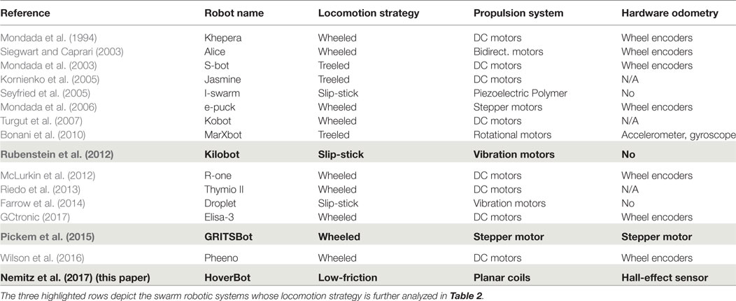
Table 1. Comparison of 16 swarm robotic systems found in the literature.
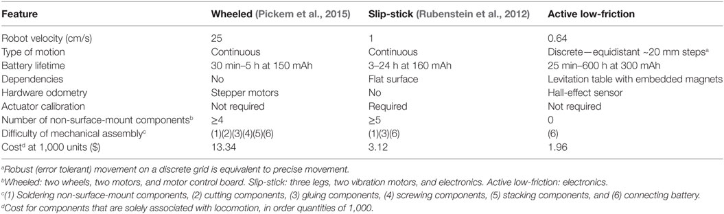
Table 2. Comparison of wheeled, slip-stick, and low-friction locomotion.
Tables 1 and 2 contain specific terminology. While most terminology for these features is self-evident, we provide here a summary for those that may be unclear. “Hardware odometry” is defined as the use of sensors to estimate change in position over time. This term indicates systems which do not possess a real form of odometry or which address the lack of hardware odometry by performing collective algorithms such as in Rubenstein et al. (2012). In this column, N/A refers to the fact that the cited publication does not explicitly state information about odometry. “Type of motion” clarifies whether a motion is continuous or discrete and if discrete with what step size. “Dependencies” refer to specific environments which the robots require to function properly. “Surface-mount-technology (SMD)” components are components which can be soldered directly onto a PCB. “Non-SMD” components are usually incompatible with pick-and-place machines and often require manual assembly which generally increases the labor effort and cost for mass manufacture.
Previous Swarm Robotic Systems
The swarm robotic systems listed in Table 1 use either wheeled or slip-stick locomotion. Slip-stick locomotion refers to the alternation between slipping and sticking of an agent to a substrate that results into directed locomotion (Vartholomeos and Papadopoulos, 2006). The vast majority of swarm robotic systems use wheeled locomotion with DC motors and wheel encoders. There are a few exceptions which use tracks and wheels (treels) and accelerometers, gyroscopes, or stepper motors for odometry. Treels are considered as wheeled locomotion. Three systems use slip-stick locomotion, whereas two of those three systems use vibration motors and the remaining system uses piezoelectric polymers as actuators. The HoverBot System is the first implementation of our active low-friction locomotion.
Comparison of Locomotion Strategies
Table 2 compares wheeled, slip-stick, and low-friction locomotion by using the GRITSBot, the Kilobot, and the HoverBot as representative systems. We selected Kilobot as a representative for slip-stick locomotion because it is the first and only large-scale robot swarm exceeding a collective size of 1,000 units. We chose GRITSBot as a representative for wheeled locomotion. Pickem et al. (2015) have presented a recent system that explores both cost and functionality.
While wheeled locomotion has advantages in robot velocity, platform independence, hardware odometry, and actuator calibration, it has disadvantages in battery lifetime, number of non-SMD components (minimum two wheels and two motors), difficulty of mechanical assembly, and cost (including motor control board). In Pickem et al.’s work, non-surface-mount components had to be soldered, receiver coil wires needed to be cut and glued, wheels had to be screwed onto motors, circuit boards needed to be stacked, and the battery had to be connected.
In comparison, slip-stick locomotion has advantages in battery lifetime and cost, but disadvantages in robot velocity, the dependency on flat surfaces, hardware odometry, actuator calibration, and number of non-SMD components (the minimum number being three legs and two vibration motors). In Rubenstein et al.’s work, their mechanical assembly consisted of soldering non-surface-mount components, gluing vibration motors to the robot, and connecting a battery.
Our active low-friction locomotion has advantages in that it provides hardware odometry, requires no actuator calibration, has no non-SMD components, simple mechanical assembly, and is low cost; but it has disadvantages in robot velocity, dependency on a levitation-magnet table, and battery lifetime. To mechanically assemble our robot, one must only connect a battery.
Overall, each of the three strategies possesses specific advantages over the others.
The contribution of this study is the introduction of an active low-friction locomotion mechanism and its first embodiment, the HoverBot system. In addition to using active low-friction locomotion, the HoverBots have the following characteristics, they:
• possess odometry by using a single Hall-effect sensor;
• only require electronic components that are surface mountable;
• only require connecting a battery to a robot as an assembly step;
• use low-cost actuators and associated circuitry;
• do not require actuator calibration;
• move precisely on a discrete grid.
Low-Friction Locomotion
To move—on land, in water, or in the air—always requires an expenditure of energy. Reducing the resistance to motion, namely, friction, allows a greater range of travel for a given input of energy (Radhakrishnan, 1998). However, instead of enhancing locomotion, we enable locomotion by reducing friction. A good example of our proposed locomotion mechanism can be observed in nature. Nannosquilla decemspinosa is a small stomatopod found in sand substrates on the Pacific coast of Central and South America. These stomatopods are capable of maneuvering if supported by a 1-mm layer of water and lose this capability once their surrounding dries up (Caldwell, 1979).
The HoverBot is conceptually similar to N. decemspinosa and is only capable of maneuvering if it is supplied with a constant air flow beneath its contact surface. The airflow reduces the friction between robot and table allowing relatively weak forces to be used for locomotion. Specifically, we embedded permanent magnets into a levitation table. The HoverBot possesses planar coils which interact with these permanent magnets, resulting in two-dimensional locomotion. Such forces would be insufficient if friction had not been reduced. This concept relaxes actuator boundaries allowing a significant simplification of the robot’s actuation and control system.
We define active low-friction locomotion as a locomotion type that enables robots to maneuver autonomously, and we define passive low-friction locomotion as locomotion type that allows robots to maneuver heteronomously.
Not included in Table 1, but relevant to our technical approach, is work from Groß et al. (2011), Napp et al. (2011), Cappelleri et al. (2014), and Pelrine et al. (2017). Groß et al. reported on an experimental setup in which they investigated aided assembly with floating building blocks using an air table. Their system used passive low-friction locomotion in which their building blocks did not possess locomotion capabilities, but modules would flow passively in the agitated medium. Napp et al. investigated stochastic interactions between active and passive robots using passive low-friction locomotion. Passive robots were foam blocks with complementary shape and embedded magnets that assembled over time on an air bed. Active robots, while not capable of autonomous movement, could expend energy to disassemble the passive robots. Cappelleri et al. introduced a novel approach to achieving independent control of multiple robot magnets. In their work, they designed a grid of planar microcoils. The coils were used to generate magnetic potentials to control the trajectories of magnets. Pelrine et al.’s work is similar to Cappelleri’s, but differs in that they add onto their PCBs a thin graphite layer that makes their magnet robots levitate. Both their work feed into additive micromanufacturing with swarms. Similarly to Groß’s and Napp’s work, agents did not possess locomotive autonomy but were moved by external stimuli; all four approaches are relevant but distinctly different to the work we present here.
The Levitation–Magnet Table
Figure 1 illustrates the concept, and our implementation, of the levitation–magnet table. The table supplies an airflow beneath the HoverBots’ contact surface creating an air cushion that reduces friction between the robot and the locomotion substrate. The differential pressure required to lift a HoverBot can be estimated according to Leal (2007) by the following equation:
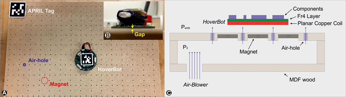
Figure 1. (A) Levitation–magnet table with a HoverBot on top. There are four AprilTags for each of the table corners (one visible in the figure) and one AprilTag attached to the HoverBot. The AprilTags are used for tracking (Olson, 2011). (B) A photograph showing an air gap between a HoverBot and the table. (C) Conceptual overview: an air blower increases pressure P2 within the air chamber. The pressure difference between Pamb and P2 causes a HoverBot to levitate, hence the friction between robot and table decreases.
Equation 1 implies that an increase in the robot’s weight or a reduction of the robot’s surface area can be encountered by an increase in differential pressure. In our experiments, we required approximately 22.5 mm H2O differential pressure to levitate HoverBots. We measured the differential air pressure between air chamber and ambient environment by using a u-tube manometer. We controlled the air blower’s supply voltage with an adjustable transformer (Variac) which varied the air blower’s output air-flow-rate, and which in-turn varied the differential pressure between the inside and outside of the levitation table.
The levitation–magnet table measures 200 mm × 300 mm and has an array of permanent magnets embedded into its surface. The permanent magnets serve a double purpose, they: (1) act as magnetic anchors that a HoverBot utilizes to maneuver and (2) give rise to a magnetic field with a discrete regular pattern of features which a HoverBot with a Hall-effect sensor can utilize for odometry. All magnets were assembled mono-directionally: north-pole facing up.
The HoverBot
A HoverBot consists of a single four-layer PCB, shown in Figure 2, and a detachable 300 mAh lithium polymer battery. The bottom layer comprises five planar actuation coils. Each HoverBot has a diameter of 39 mm and weighs 19.4 g with, and 7.4 g without, a battery. HoverBot possesses a low-power microcontroller, programming and debug ports, an infrared transceiver, a Hall-effect sensor, and a transistor circuit.
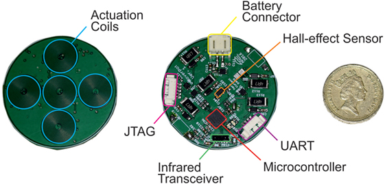
Figure 2. A HoverBot. The bottom layer of the HoverBot consists of an array of five planar actuation coils. Its top layer is populated with Hall-effect and infrared sensors and a low-power (SAMD21E) microcontroller. The battery of a HoverBot is detached in this figure.
Actuation
We embedded the planar coils in a cross-formation into the bottom layer of the PCB. Each actuation coil has 17 turns and a trace width of 150 µm. A trace width of 150 µm and one trace thickness allows maximum currents of approximately 300 mA based on the Generic Standard on the Printed Board Design (IPC-2221) charts. We set the maximum current per coil to 500 mA, which induces a magnetic field of 1.1 mT. Our design uses a maximum current that is greater than the suggested standard, because we decided to evaluate the circuitry to its upper limits. We measured the magnetic field by using an InvenSense MPU-9250 magnetometer. We placed the magnetometer onto the core of the center coil.
Each coil is connected in series with a current limiting resistor and a transistor. If the transistor switches on, a constant voltage is applied across the coil and resistor. The transistor’s switching behavior is controlled by a pulse-width-modulated (PWM) signal from the microcontroller. We control the amount of current through the coil by changing the duty cycle of the PWM. The magnetic field of a solenoid can be approximated by Ampere’s law:
where B is magnetic flux density, μ is permeability; n is turn density; I is current; N is the number of turns; and L is unit length.
Fundamentally similar to Eqs 2–3, the magnetic field of a planar coil is dependent on the coil’s turn density and the current flow. The number of turns is identical for every HoverBot. However, the coil, trace, and current limiting resistor resistance could vary due to manufacturing tolerances and cause a change of current flow for a given duty cycle. We measured the average series resistance of 15 actuation circuits of a total of 3 HoverBots with a Fluke 115 multimeter. The SD was 0.1 Ohm, which causes a current change of 7 mA. Hence, the potential current fluctuations are less than 1.5% and can be neglected. HoverBots do not require any kind of actuator calibration.
Sensing and Communication
A HoverBot possesses infrared and Hall-effect sensors. The Hall-effect sensor can be used for odometry and the detection of local magnetic fields. The infrared transceiver can be used for robot-to-computer communication. Our current HoverBot version does not allow robot-to-robot communication due to limitations in its hardware configuration. It only possesses a single IR transceiver pointing upwards.
Programming and Debugging
A HoverBot has programming and debug ports (IR transceiver, JTAG and UART). We programmed the HoverBot via JTAG using an Atmel SAM-ICE programmer. Therefore, this HoverBot version requires a wired connection to be programmed. We debugged HoverBot via infrared using an infrared handheld device.
Power System
A HoverBot has 3.7 V 300 mAh lithium polymer batteries attached to it. We calculated the minimum battery life by accumulating the currents that occur during locomotion. The current locomotion strategy requires a constant current of approximately 720 mA, which allows a minimum battery life of around 25 min. However, lithium polymer batteries should never be completely discharged due to their chemistry. We wrote a battery-watch program to monitor the battery during runtime, and this program shuts down all circuitry when the battery reaches 90% depletion. The maximum battery life is calculated by considering HoverBot when in sleep mode, in which it approximately consumes 500 µA. In this low-power mode, the HoverBot’s battery life time rises to around 600 h or 25 days. In this HoverBot version, the lithium polymer batteries have to be detached for charging. We charged the batteries by using a Turnigy Micro-6 LiPoly battery charger.
Locomotion Strategy
The HoverBot levitates on air cushions and maneuvers by sequentially energizing its planar coils to pull itself toward magnetic anchors. Figure 3 indicates a HoverBot’s open-loop locomotion strategy. A single step, a movement from one magnetic anchor to another, is decomposed into three part steps. In step 1, HoverBot starts from its idle state in which its center coil is aligned with a magnet, and the other four coils are each overlapping with adjacent magnets. The HoverBot simultaneously actuates one side coil with maximum current and the opposite side coil with medium current. This actuation results in an overall movement to the right while preventing HoverBot from rotating. Subsequent steps are conceptually the same, but each step requires a differing pair of coils to be actuated. Three of these steps are required for a HoverBot to move from one magnet to another. This actuation scheme only enables complete magnet-to-magnet movements. A change of direction during a part step has not been investigated. The relative positions of the HoverBot coils and the magnets are crucial for this actuation scheme. We chose magnet-to-magnet and coil-to-coil pitches based on Eq. 4 to ensure a 50% overlap between actuator coil and an adjacent magnet at any given step assuming that coil and magnet diameters match. Therefore, HoverBot’s minimum step size is the pitch between adjacent magnets (2 cm pitch).
where dm is magnet to magnet pitch; dc is coil to coil pitch; dmc is magnet to coil pitch; and rmc,c is ratio of dmc to dc.
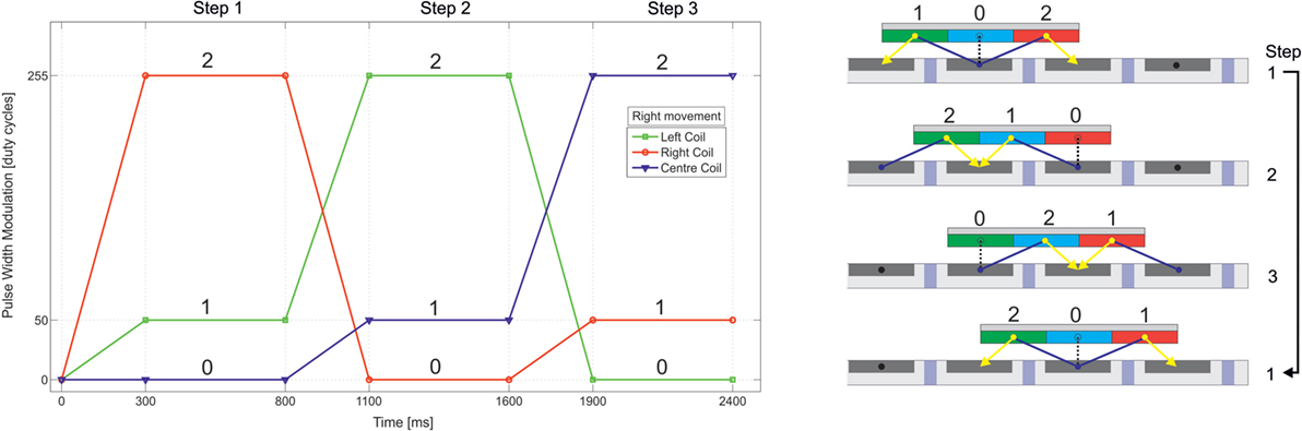
Figure 3. The illustrated actuation scheme describes a movement to the right. The other directions can be derived from this actuation profile. A HoverBot moves from one magnetic anchor to another by performing three steps. Starting in idle state (step 1), a HoverBot always actuates two coils at the time for any given step since we require two points in space to maintain the orientation of a plain. Therefore, this actuation sequence prevents rotation during movement.
A HoverBot moves in a two-dimensional discrete environment. The programmer cannot deliberately rotate a HoverBot or move it in any other trajectories than the Manhattan Geometry.
Odometry
Figure 4 is based on the Hall-effect sensor readings from a HoverBot during movement which were paired with spatial information from the AprilTags. While a HoverBot moves from one magnetic anchor to another (2 cm pitch), its Hall-effect sensor measures a continuously changing magnetic flux density as indicated in Figure 4. The Hall-effect sensor is centered above the center coil and is capable of measuring magnetic flux densities from −73 to +73 mT. The maximum readings occur when the HoverBot’s center coil is aligned with a magnetic anchor. Although our current actuation scheme operates as an open-loop control, the magnetic flux density changes over distance depict distinct features in the two-dimensional space which could be utilized as feedback for closed-loop control. We have not experienced distorted sensor (Hall-effect, IR) readings due to magnetic interference.
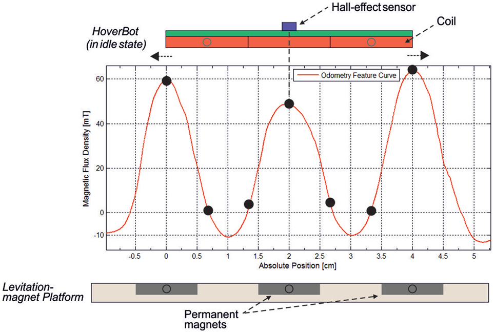
Figure 4. Experimental results showing that the magnetic flux density peaks correspond to the centers of the permanent magnets. The magnets are 2 cm displaced from one another. A HoverBot in idle state aligns with its Hall-effect sensor above a magnet. A step from one magnet to another causes the Hall-effect sensor to measure a peak-to-peak magnetic field curve. Specifically, a movement is decomposed into three individual steps in which the Hall-effect sensor measures a distinct magnetic flux density after each step, as indicated by a black dot.
Manufacture and Cost
The circuitry of a HoverBot only consists of surface-mount components as indicated in Table 2. HoverBot is designed explicitly for manufacturability; it consists of a single PCB and therefore mass manufacture is a simple case of placing a batch order with a PCB foundry. HoverBots can be autonomously populated with pick-and-place machines at the point of manufacture. Assembly of one robot takes seconds since it only consists of plugging in a battery to a HoverBot, also indicated in Table 2. The fabrication of the levitation–magnet table is described in detail in Section “Fabrication.”
Table 3 summarizes the costs of the current levitation–magnet table and HoverBots in order quantities of 15. The levitation–magnet table costs $235 whereas each HoverBot costs $22.37 in quantities of 15 and $11.88 in quantities of 1,000 s. The most expensive part of the levitation–magnet table is the variable transformer at $135. The costs for components that are solely associated with HoverBot’s actuation system (transistors, shunt resistors, diodes, and capacitors) are $1.96 in order quantities of 1,000 as indicated in Table 2.
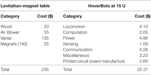
Table 3. Cost summary for HoverBots in order quantities of 15 units, and for one levitation–magnet table.
The bill of materials, HoverBot system design files, and code are available on request.
Evaluation
To evaluate the HoverBot system we designed a controllable experimental setup. We used artificial features (fiducials)—AprilTags (Olson, 2011)—which we placed on top of the HoverBot and at each corner of the table. AprilTags are robust to occlusions and lens distortion while being very efficient in achieving detection rates of 20 Hz in our setting. To measure the accuracy of the HoverBot, we tracked the centroid and the orientation of the robot by detecting the corresponding AprilTag. Figure 5 depicts the main features of the tracking system. This system can run for hundreds of minutes without human intervention, thereby automating the data acquisition pipeline. We used a Chameleon 1.3 MP Color (Sony IXC445) camera and a Tamron 13FM28IR 2.8 mm f/1.2 day/night lens.
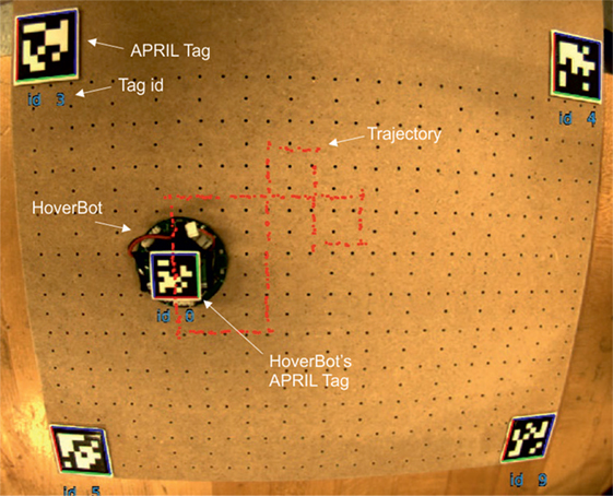
Figure 5. Experimental setup to evaluate a HoverBot’s locomotion performance. We placed one AprilTag in each corner of the levitation–magnet table. These tags serve as reference points and allow determination of a HoverBot’s relative position over time. Each AprilTag corresponds to an ID number. During experiments, we read out each AprilTag’s ID, x-position, y-position, and rotation. The red line indicates a HoverBot’s trajectory, which reinforces with each lap.
We tested the HoverBot system and its low-friction locomotion by conducting eleven experiments that lasted a total of 3 h and more than 10,000 steps. In these experiments, the HoverBot circled on an arbitrary trajectory until it was nearly discharged. We used a set of AprilTags to track the HoverBot over time and subsequently evaluated its distance traveled, velocity, and number of missteps (errors). With our current actuation sequence, the HoverBot moves an average of 0.64 cm/s with an SD of 0.015 cm/s. We did not observe any missteps or accidental rotations during these three hours. A “misstep” is defined as an unsuccessful series of energized coils that results in the robot staying on its previous position. An “accidental rotation” is defined as an inadvertent robot rotation by 45° due to local table imperfections (e.g., air flow fluctuations) or collisions with other robots or static objects. A video recording of this experiment is provided by the Supplemental Video—SV1.1
Although the HoverBot moves robustly, we observed unintentional shaking in all four directions during movement. Therefore, we compared moved distance, which includes the total distance including unintentional shaking, with effective distance, which is the actual distance between waypoints. We define ε by the following term:
We found that ε is 2.29 (on average) with an SD of 0.27. An ε of 2.29 explicitly states that the HoverBot moves more than two times the distance it travels. ε is directly related to the actuation scheme. We chose an actuation scheme that is relatively slow, but very robust by performing zero missteps over three hours of experiments. ε can be further reduced by changing the actuation scheme and specifically the timing and amount of current that flows through up to five coils simultaneously.
Recovery from a Locked Rotational Position
Although we have not experienced any accidental rotation incidents during three hours of testing, we developed an actuation strategy that allows a HoverBot to recover from a locked position. As shown by Figure 4, the Hall-effect sensor measures a local magnetic minimum if a HoverBot is locked due to accidental rotation. When a HoverBot recognizes this state, it can execute a recovery actuation scheme. It first actuates only its center coil to change from the position in Figure 6A to the position in Figure 6B. Then it actuates, in addition, a side coil to regain the correct orientation as indicated in Figure 6C. We recorded this sequence, a video–recording of this experiment is provided by the Supplemental Video—SV2.2
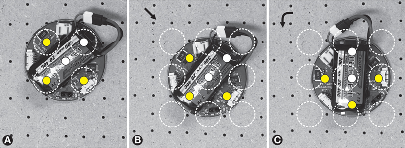
Figure 6. Recovery in locked position. (A) A HoverBot is locked in a 45°-angled position. Four of its five coils are aligned with permanent magnets. (B) The HoverBot rapidly pulsed (only) its center coil and regained center coil alignment with a permanent magnet. (C) The HoverBot additionally actuated a side coil and regained a slightly shifted idle position. At this stage, the HoverBot is reenabled to move.
Demonstration
In addition to our quantitative evaluation of HoverBot’s locomotion capabilities, we performed four additional demonstrations to give more insights into the nature of the HoverBot system. Figure 7 indicates two HoverBots moving in formation (A), moving randomly, colliding, and recovering from rotation (B), colliding (C), and colliding while one robot is in sleep mode, acting as a passive agent (D).
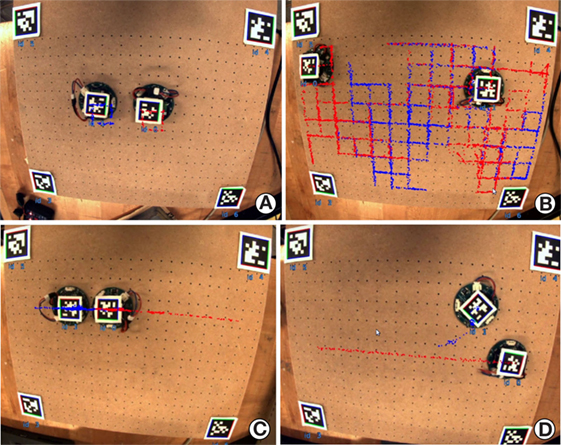
Figure 7. Demonstrations of the locomotion capabilities of multiple HoverBots. (A) Two HoverBots circle in formation until they are unsynchronized—video SV1. (B) Two HoverBots move randomly, collide, and recover—video SV2. (C) Two HoverBots collide frontally with one another—video SV3. (D) One HoverBot collides with a passive HoverBot—video SV4. Red and blue trajectories depict the HoverBot’s movements over time.
We observed that two HoverBots that move independently in formation become unsynchronized over time due to oscillator imperfections. Physical inter-robot interactions can either result in robots maintaining their position after collision, which likely happens in a frontal collision event, or robots loose orientation and have to recover. The random collision demonstration also indicates possible orientation loss due to rapid and constant change in direction. Those incidents, however, are scarce, they were detected, and were recovered from. In most cases, moving HoverBots are capable of pushing passive agents, sliding them to one side, or pushing them in front, in the direction of travel. However, we recorded one incident in which a moving agent could not pass a passive agent due to a specific physical orientation. Video recordings of the experiments which correspond to Figures 7A–D are provided by the Supplemental Videos—SV3–SV6.3
Discussion
Battery Life and Robot Velocity
HoverBot possesses a relatively short battery lifetime (~25 min) due to high coil actuation currents that are required to achieve magnetic fields of approximately 1.1 mT. According to Eqs 2 and 3, the magnetic field is linearly dependent on the actuation current, but also on the number of coil windings. An increase of coil windings as well as the stacking of planar coils (multilayer PCBs) could significantly decrease the power consumption.
The existing robot velocity can be improved without an increase of power consumption. The product of current and time for slow coil actuation does not change for rapid coil actuation. HoverBot’s velocity is currently slow because we wanted to start off with a robust actuation scheme. Future work will have to investigate faster actuation schemes. It is very likely that actuator calibration will become necessary once we reach HoverBot’s physical speed limits. The actuation schemes will become more delicate and have to energize the actuation coils extremely precisely, both in terms of the amount, duration, and direction of current flows. One solution to this control problem could be to use machine learning algorithms. An external camera system could send feedback to the HoverBot agent and inform the controller whether movement was successful or not.
Ease of Robot Fabrication
Although HoverBots only consist of surface-mount components, we believe the importance of this advantage will decrease over time. The current state of swarm robotics research requires low-cost, easy-to-fabricate, and easy-to-use swarm robotic systems. However, once we obtain a better understanding of complex systems and how emergence occurs, cost and ease of fabrication will become secondary because the risk-factors involved in deploying swarms (system failure, loss of control, and safe and reliable operation) will have decreased. Furthermore, there are many great examples in industry in which very sophisticated products have been mass manufactured (computers, cars, airplanes, etc.). Investing into an expensive swarm of robots will become worthwhile once we know how to safely operate and control it.
The Table
The existing ratio of magnet-to-magnet and coil-to-coil distances was chosen to simplify HoverBot’s actuation circuitry by only requiring coils to be energized in one direction. In future work, we can investigate the use of H-bridge drivers to improve locomotion by allowing bidirectional currents to energize the actuator coils. There may also be a benefit of designing different magnet patterns, such as those which that vary between polarities as well as exploit different geometric constellations (e.g., concentric patterns).
Scaling the System
The current table measures 200 mm × 300 mm, and this size limits the maximum number of robots on the table to 35, assuming a lattice robot formation without extra space for movement and a robot diameter of 40 mm. There is no reason why the table or robot could not be scaled in either direction. The table size could be significantly increased, to the size of an air hockey table for example. The differential pressure that causes the robots to levitate can be easily increased by using a more powerful blower, or even several at once. An increase in differential pressure would allow greater payloads to be carried by the robots. The robot size could be significantly increased or decreased. There are micromachining systems that are capable of fabricating 50 μm wide copper traces (e.g., LPKF Protolaser U3) allowing much smaller actuator coil sizes. The 300 mAh battery could be substituted with less powerful batteries or even replaced with solar panels.
Future Directions
HoverBot version-2 should possess four directional communications to increase further its utility as swarm algorithmic testbed.
The collision of an active with a passive robot in video SV6 indicate an opportunity for new swarm robotic algorithms in which passive and active robots are being utilized to achieve a task. A passive robot might become active if it has not been pushed around by another robot for a defined period of time. A passive robot might also specialize in sensing and inform active robots about its observations. This heterogeneity might lead to strategies that optimize the power budget of the swarm while solving the task at hand.
The formation demonstration in video SV3 indicates that the HoverBot system can be used for even larger collective movements. This behavior is difficult to achieve with wheeled or slip-stick actuated swarm systems since such systems move in continuous space and must rotate to change directions. HoverBots locomotion can be compared with that of quadrotors in formation flight (Kushleyev et al., 2013), maintaining orientation of the local and global directions.
Almost all of HoverBot’s advantages originate from its minimalist design. HoverBots levitate, move precisely on a discrete grid, and are capable of verifying a step by measuring continuously magnetic flux densities. We will utilize this combination of discrete motion with continuous local perception to study search and tracking as well as mapping algorithms. An excellent starting point is Senanayake review on search and tracking algorithms for swarm robots (Senanayake et al., 2014).
Conclusion
In this study, we introduced a new locomotion strategy, active low-friction locomotion, and showed its first embodiment: the HoverBot system. We demonstrated HoverBot’s capabilities by performing six different experiments ranging from moving in a predetermined trajectory, to random movement and inter-robot collisions. Active low-friction locomotion is an alternative to wheeled- and slip-stick locomotion in the field of swarm robotics. The HoverBot system possesses odometry by using a single Hall-effect sensor, it only requires components that are surface mountable, it only requires connecting a battery as assembly step, it uses low-cost actuators and associated circuitry, does not require actuator calibration, and moves precisely on a discrete grid. The HoverBot systems offer a unique combination of discrete precise motion with continuous local perception. Its hardware can be easily extended with additional sensors. Potential research directions using this embodied-simulation system will include search and tracking, or mapping with robot swarms. The HoverBot system serves as a testbed for new hardware and algorithms.
Fabrication
Fabrication of Levitation–Magnet Table
We purchased 10 mm wide and 3 mm thick cylindrical N42 magnets from Amazon. We bought 12.7 mm thick medium-density fiberboard from a local hardware store. We used a ShopBot Buddy to mill and drill holes. We used a 0.063″ drill bit for the air-holes and a 0.394″ end-mill for the magnet pockets. We placed the top-plate of the air table on an optics (metal) table and embedded the magnets mono-directionally (polarity) into the pockets. We used an Arrow TR400 glue gun to fix the magnets in the pockets. We used a Mcculloch MCB2205 leaf blower as the air source in combination with a Circuit Specialists 16VA520T20 Variac for airflow control. The air blower listed in Table 3 is the Black & Decker BV5600 High Performance Blower (for price reference) and is equivalent to the MCB2205. We leveled the levitation–magnet table using a water scale.
Fabrication of a HoverBot
We purchased all electronics components from Digikey. The circuit boards were designed with CadSoft Eagle and manufactured by 4PCB.com. We soldered the components by using a hot air pencil and an airbath preheating system from Zephyrtronics.
Author Contributions
MN: created the system and is lead author of all sections of the work. MS: contributed building the HoverBot table, developing the experiment scheme, and revised the manuscript. JM: contributed building the HoverBot agent. GF: contributed to the AprilTag setup, data analysis, revising and partly writing the manuscript. LT and RM: contributed to the manuscript/revision and the development of the table. EO and AH: advised on building the HoverBot system. AS: lead advisor and primary editor of the manuscript.
Conflict of Interest Statement
No competing financial interests exist. The subject matter in this study forms the basis of patent application GB 1611448.0.
Acknowledgments
MN thanks Victoria Edwards (PhD student, University of Michigan) for her helpful comments on the manuscript.
Funding
MN gratefully acknowledges support from the Centre in Doctoral Training in Intelligent Sensing and Measurement (EP/L016753/1), UK and the Office of Naval Research (N00014-13-1-0217), USA. This work was supported by EPSRC through the Robotarium Capital Equipment (EP/L016834/1).
Footnotes
- ^http://edin.ac/2wxEE5w.
- ^http://edin.ac/2wcISwJ.
- ^SV3: Formation: http://edin.ac/2wxt0aN, SV4: Random Collision: http://edin.ac/2wdsDzt, SV5: Collision (active): http://edin.ac/2wwTTeJ, SV6: Collision (passive): http://edin.ac/2wd3h4Y.
References
Bonabeau, E., Dorigo, M., and Theraulaz, G. (1999). Swarm Intelligence: From Natural to Artificial Systems, Vol. 1. New York, NY: Oxford University Press.
Bonani, M., Longchamp, V., Magnenat, S., Rétornaz, P., Burnier, D., Roulet, G., et al. (2010). “The marXbot, a miniature mobile robot opening new perspectives for the collective-robotic research,” in IEEE/RSJ 2010 International Conference on Intelligent Robots and Systems, IROS 2010 – Conference Proceedings, Taipei, 4187–4193.
Brambilla, M., Ferrante, E., Birattari, M., and Dorigo, M. (2013). Swarm robotics: a review from the swarm engineering perspective. Swarm Intell. 7, 1–41. doi: 10.1007/s11721-012-0075-2
Caldwell, R. L. (1979). A unique form of locomotion in a stomatopod – backward somersaulting. Nature 282, 71–73. doi:10.1038/282071a0
Cappelleri, D., Efthymiou, D., Goswami, A., Vitoroulis, N., and Zavlanos, M. (2014). Towards mobile microrobot swarms for additive micromanufacturing. Int. J. Adv. Robot. Syst. 11(9), 150. doi:10.5772/58985
Caprari, G., and Siegwart, R. (2003). “Design and control of the mobile micro robot alice,” in Proceedings of the 2nd International Symposium on Autonomous Minirobots for Research and Edutainment AMiRE 2003 (Brisbane: CITI), 22–32.
Farrow, N., Klingner, J., Reishus, D., and Correll, N. (2014). “Miniature six-channel range and bearing system: algorithm, analysis and experimental validation,” in Proceedings – IEEE International Conference on Robotics and Automation, Hong Kong, 6180–6185.
GCtronic. (2017). Elisa-3. Available at: http://www.gctronic.com/doc/index.php/Elisa-3
Groß, R., Magnenat, S., Küchler, L., Massaras, V., Bonani, M., and Mondada, F. (2011). “Towards an autonomous evolution of non-biological physical organisms,” in Lecture Notes in Computer Science (Including Subseries Lecture Notes in Artificial Intelligence and Lecture Notes in Bioinformatics), Budapest, Vol. 5777 LNAI, 173–180.
Kornienko, S., Kornienko, O., and Levi, P. (2005). “Minimalistic approach towards communication and perception in microrobotic swarms,” in 2005 IEEE/RSJ International Conference on Intelligent Robots and Systems, IROS, Edmonton, 4005–4011.
Kushleyev, A., Mellinger, D., Powers, C., and Kumar, V. (2013). Towards a swarm of agile micro quadrotors. Auton. Robots 35, 287–300. doi:10.1007/s10514-013-9349-9
Leal, L. G. (2007). Advanced Transport Phenomena: Fluid Mechanics and Convective Transport Processes. Cambridge University Press, 934.
McLurkin, J., Lynch, A. J., Rixner, S., Barr, T. W., Chou, A., Foster, K., et al. (2012). “A low-cost multi-robot system for research, teaching, and outreach,” in Springer Tracts in Advanced Robotics, Vol. 83 STAR, Lausanne, 597–609.
Moeslinger, C., Schmickl, T., and Crailsheim, K. (2011). “A minimalist flocking algorithm for swarm robots,” in Lecture Notes in Computer Science (Including Subseries Lecture Notes in Artificial Intelligence and Lecture Notes in Bioinformatics), Vol. 5778 LNAI, Budapest, 375–382.
Mondada, F., Bonani, M., Raemy, X., Pugh, J., Cianci, C., Klaptocz, A., et al. (2009). “The e-puck, a robot designed for education in engineering,” in Proceedings of the 9th Conference on Autonomous Robot Systems and Competitions, Vol. 1, (IPCB, Instituto Politécnico de Castelo Branco), 59–65. No. LIS-CONF-2009-004.
Mondada, F., Franzi, E., and Ienne, P. (1994). Mobile Robot Miniaturisation: A Tool for Investigation in Control Algorithms. Exp. Robot. 501–513.
Mondada, F., Guignard, A., Bonani, M., Bar, D., Lauria, M., and Floreano, D. (2003). “SWARM-BOT: from concept to implementation,” in Proceedings. 2003 IEEE/RSJ International Conference on Intelligent Robots and Systems, 2003. (IROS 2003), Vol. 2. (IEEE), 1626–1631.
Napp, N., Burden, S., and Klavins, E. (2011). Setpoint regulation for stochastically interacting robots. Auton. Robots 30, 57–71. doi:10.1007/s10514-010-9203-2
Olson, E. (2011). “AprilTag: a robust and flexible visual fiducial system,” in Proceedings – IEEE International Conference on Robotics and Automation, Shanghai, 3400–3407.
Pelrine, R., Hsu, A., Cowan, C., and Wong-Foy, A. (2017). “Multi-agent systems using diamagnetic micro manipulation—from floating swarms to mobile sensors,” in International Conference on Manipulation, Automation and Robotics at Small Scales (MARSS) (Seattle, WA: IEEE), 1–6.
Pickem, D., Lee, M., and Egerstedt, M. (2015). “The GRITSBot in its natural habitat – a multi-robot testbed,” in Proceedings – IEEE International Conference on Robotics and Automation, 4062–4067.
Radhakrishnan, V. (1998). Locomotion: dealing with friction. Curr. Sci. 74, 826–840. doi:10.1073/pnas.95.10.5448
Riedo, F., Chevalier, M., Magnenat, S., and Mondada, F. (2013). “Thymio II, a robot that grows wiser with children,” in Proceedings of IEEE Workshop on Advanced Robotics and Its Social Impacts, ARSO, Tokyo, 187–193.
Rubenstein, M., Ahler, C., and Nagpal, R. (2012). “Kilobot: a low cost scalable robot system for collective behaviors,” in Proceedings – IEEE International Conference on Robotics and Automation, St. Paul, MN, 3293–3298.
Rubenstein, M., Cornejo, A., and Nagpal, R. (2014). Programmable self-assembly in a thousand-robot swarm. Science 345, 795–799. doi:10.1126/science.1254295
Senanayake, M., Senthooran, I., Barca, J. C., Chung, H., Kamruzzaman, J., and Murshed, M. (2014). Search and tracking algorithms for swarms of robots: a survey. Rob. Auton. Syst. 75, 422–434. doi:10.1016/j.robot.2015.08.010
Seyfried, J., Szymanski, M., Bender, N., Estaña, R., Thiel, M., and Wörn, H. (2005). The I-SWARM project: intelligent small world autonomous robots for micro-manipulation. Swarm Robot. 3342, 70–83. doi:10.1007/978-3-540-30552-1_7
Turgut, A. E., Goekce, F., Celikkanat, H., Bayindir, L., and Sahin, E. (2007). Kobot: a mobile robot designed specifically for swarm robotics research. Architecture 32–42.
Vartholomeos, P., and Papadopoulos, E. (2006). “Analysis, design and control of a planar micro-robot driven by two centripetal-force actuators,” in Proceedings – IEEE International Conference on Robotics and Automation, Orlando, FL, 649–654.
Wilson, S., Gameros, R., Sheely, M., Lin, M., Dover, K., Gevorkyan, R., et al. (2016). Pheeno, a versatile swarm robotic research and education platform. IEEE Robot. Autom. Lett. 1, 884–891. doi:10.1109/LRA.2016.2524987
Keywords: HoverBot, swarm robots, design for manufacturability, low-friction locomotion, precise locomotion, robot testbed, physical simulation
Citation: Nemitz MP, Sayed ME, Mamish J, Ferrer G, Teng L, McKenzie RM, Hero AO, Olson E and Stokes AA (2017) HoverBots: Precise Locomotion Using Robots That Are Designed for Manufacturability. Front. Robot. AI 4:55. doi: 10.3389/frobt.2017.00055
Received: 08 June 2017; Accepted: 13 October 2017;
Published: 06 November 2017
Edited by:
Simon Garnier, New Jersey Institute of Technology, United StatesReviewed by:
Sabine Hauert, University of Bristol, United KingdomHeiko Hamann, University of Lübeck, Germany
Copyright: © 2017 Nemitz, Sayed, Mamish, Ferrer, Teng, McKenzie, Hero, Olson and Stokes. This is an open-access article distributed under the terms of the Creative Commons Attribution License (CC BY). The use, distribution or reproduction in other forums is permitted, provided the original author(s) or licensor are credited and that the original publication in this journal is cited, in accordance with accepted academic practice. No use, distribution or reproduction is permitted which does not comply with these terms.
*Correspondence: Markus P. Nemitz, m.nemitz@ed.ac.uk, nemitz@umich.edu;
Adam A. Stokes, a.a.stokes@ed.ac.uk